
Read through carefully and understand these instructions before use.
Diese Anleitung vor Benutzung des Werkzeugs sorgfältig durchlesen und verstehen.
∆ιαάστε πρσεκτικά και κατανήσετε αυτές τις δηγίες πριν τη ρήση.
Przed użytkowaniem należy dokładnie przeczytać niniejszą instrukcję i zrozumieć jej treść.
Használat előtt olvassa el figyelmesen a használati utasítást.
Před použitím si pečlivě přečtěte tento návod a ujistěte se, že mu dobře rozumíte.
Aleti kullanmadan önce bu klavuzu iyice okuyun ve talimatlar anlayn.
Bнимaтeльно пpочтитe дaннyю инcтpyкцию по экcплyaтaции пpeждe чeм пользовaтьcя инcтpyмeнтом.
Variable speed
DV 14DL • DV 18DL
Cordless Impact Driver Drill
Akku-Schlagbohrschrauber
¢Ú··ÓÔηÙÛ¿‚È‰Ô Ì·Ù·Ú›·˜ ÎÚÔ˘ÛÙÈÎfi
Akumulatorowa wiertarko-wkrętarka udarowa
Akkus ütvefúró-csavarozó
Akku rázový utahovák
Akülü darbeli vidalama matkap
Удapный aккyмyлятоpный шypyповepт
Handling instructions
Bedienungsanleitung
δηγίες ειρισµύ
Instrukcja obsługi
Kezelési utasítás
Návod k obsluze
Kullanm talimatlar
Инcтpyкция по экcплyaтaции
DV18DL

1
7
6
5
4
3
2
1
3
1
2
3
6
5
4
A
B
C
D
E
A
C
F
G
G
I
H
0
0
1
2
8
7
9
10
98
M
N
O
Q
P
L
K
J
3
2
1

2
18
1
4
5
2
(A)
(B)
3
11
12 13
14
16
15
17
19
\
]
`
W
X
Y
W
\
]
[
R
T
S
U
R
T
V
1
4
5
2
3
W
(A)
(B)
Z

3
20
21
22
23
24
25
26
j
3mm
11.5mm
g
h
i
a
c
b
e
d
f

4
English Deutsch Ελληνικά Polski
14.4 V Rechargeable
battery (For DV14DL)
18 V Rechargeable
battery (For DV18DL)
Latch
Pull out
Insert
Handle
Insert
Pilot lamp
Hole for connecting the
rechargeable battery
Drill mark
Hammer mark
Cap
Triangle mark
Weak
Strong
Black line
Shift knob
Low speed
High speed
Rotation change lever
Save mode (S)
Power mode (P)
Sleeve
Tighten
Loosen
Trigger switch
Selector button
Hook
Loosen
Screw
Spring
Larger diameter faces
away
Hook with light
Phillips-head screwdriver
Screw
Arrow
Hook cover
Indentation
Protuberance
AAAA batteries
Concave
Side handle
Rotate preventing protrusion
Slip preventing protrusion
Tighten
Loosen
Wear limit
Nail of carbon brush
Protrusion of carbon
brush
Contact portion outside
brush tube
1
2
3
4
5
6
7
8
9
0
A
B
C
D
E
F
G
H
I
J
K
L
M
N
O
P
Q
R
S
T
U
V
W
X
Y
Z
[
\
]
`
a
b
c
d
e
f
g
h
i
j
14,4 V
Επαναρτιµενη
µπαταρία (Για DV14DL)
18 V
Επαναρτιµενη
µπαταρία (Για DV18DL)
Μάνδαλ
Τραήτε έω
Εισωρήστε
ερύλι
Εισωρήσετε
∆κιµαστική λάµπα
Τρύπα για την σύνδεση της
επαναρτιµενης µπαταρίας
Σηµάδι τρυπανιύ
Σηµάδι σύρας
Κάλυµµα
Σηµάδι τριγώνυ
Αδύνατ
∆υνατ
Μαύρη γραµµή
Κυµπί αλλαγής
αµηλή ταύτητα
Υψηλή ταύτητα
Μλς αλλαγής περιστρής
ικνµικς τρπς
λειτυργίας απθήκευσης (S)
Ισυρς τρπς λειτυργίας (P)
Περίληµα
Σίτε
αλαρώστε
Σκανδάλη διακπτης
Κυµπί επιλγέα
Γάντς
Xαλαρώστε
Βίδα
Ελατήρι
Η µεγαλύτερη
διάµετρς λέπει πρς
άλλη κατεύθυνση
Γάντς µε ως
Κατσαίδι κεαλής
Phillips
Βίδα
Βέλς
Κάλυµµα αγκίστρυ
Αυλάκωση
Πρεή
ΑΑΑΑ µπαταρίες
Κίλ
Πλευρική λαή
Πρεή απτρπής περιστρής
Πρεή απτρπής λίσθησης
Σίτε
αλαρώστε
ρι θράς
Καρί καρυνακιύ
Πρεή
καρυνακιύ
Τµήµα επαής έω απ
τ σωλήνα της ψήκτρας
14,4 V aufladbare
Batterie (Für DV14DL)
18 V aufladbare Batterie
(Für DV18DL)
Verriegelung
Herausziehen
Einsetzen
Handgriff
Einsetzen
Kontrollampe
Anschlußloch für
Ladebatterir
Bohrer-Zeichen
Hammermarkierung
Kappe
Dreiecksmarkierung
Schwach
Stark
Schwarze Linie
Schaltknopf
Kleine Geschwindigkeit
Große Geschwindigkeit
Drehrichtungs-Wahlhebel
Energiesparmodus (S)
Leistungsmodus (P)
Manschette
Anziehen
Lösen
Trigger
Wählhebel
Haken
Lösen
Schraube
Feder
Der große Durchmesser
weist zur anderen Seite
Haken mit Beleuchtung
Kreuzschlitzschrauben-
zieher
Schraube
Pfeil
Hakenabdeckung
Einkerbung
Vorsprung
Batterien der Größe
AAAA
Konkav
Seitengriff
Schlupfverhütungsvorsprung
Drehverhütungsvorsprung
Anziehen
Lösen
Verschließgrenze
Klaue der Kohlebürste
Krempe der
Kohlebürste
Kontaktteil außerhalb
des Bürstenrohrs
Akumulator 14,4 V
(do DV14DL)
Akumulator 18 V
(do DV18DL)
Zapadka
Wyciągnij
Włóż/wprowadź
Rączka
Włóż/wprowadź
Lampka kontrolna
Otwór wsuwowy
akumulatora
Symbol wiercenia
Symbol młotka
Pierścień regulacyjny
Trójkątny symbol
Mały
Duży
Czarna linia
Zmieniacz
Mała prędkość/niskie obroty
Duża prędkość/wysokie obroty
Dźwignia zmiany obrotu
Tryb bezpieczny (S)
Tryb zasilania (P)
Tuleja
Zaciśnij
Zluzuj/zwolnij
Spust
Przełącznik kierunku obrotów
Hak
Zluzuj/zwolnij
Śruba/wkręt
Sprężyna
Większa średnica jest
odwrócona
Hak ze światłem
Wkrętak Philipsa/
z gniazdkiem krzyżykowym
Śruba/wkręt
Strzałka
Pokrywa haka
Nacięcie
Wypukłość
Baterie AAAA
Wgłębienie
Uchwyt boczny
Występ zapobiegający obracaniu
Występ zapobiegający ślizganiu
Zaciśnij
Poluzować
Ogranicznik zużycia
Końcówka szczotek
węglowych
Wypukłość elementu
węglowego
Element kontaktowy na
zewnątrz komory szczotek

5
Magyar Čeština Türkçe Pyccкий
14,4 V-os tölthető akkumulá
tor (DV14DL-hez)
18 V-os tölthető akkumulá
tor (DV18DL-hez)
Retesz
Kihúzni
Bedugni
Markolat
Bedugni
Jelzőlámpa
Nyílás a tölthető akkumulá
tor csatlakoztatásához
Fúró jel
Kalapács jel
Fedél
Háromszög alakú jel
Gyenge
Erős
Fekete vonal
Váltógomb
Alacsony fordulatszám
Magas fordulatszám
Forgásirányváltó kar
Takarékos üzemmód (S)
Normál üzemmód (P)
Karmantyú
Meghúzás
Kilazítás
Kapcsoló ravasz
Választógomb
Kampó
Meglazítani
Csavar
Rúgó
A nagyobb átmérő az
ellenkező irány felé néz
Kampó, lámpával
Keresztfejes (Phillips-)
csavarhúzó
Csavar
Nyíl
A kampó fedele
Bemélyedés
Kidudorodás
AAAA méretű
szárazelemek
Konkáv
Oldalsó fogantyú
Elfordulás gátló kiemelkedés
Csúszásgátló kiemelkedés
Meghúzás
Meglazítani
Megengedett kopás
A szénkefe szöge
A szénkefe kidudorodó
része
Érintkező rész a szénkefe
csövén kívül
14,4V Akumulátor
(Pro DV14DL)
18V Akumulátor
(Pro DV18DL)
Zámek
Zatáhnout
Zasunout
Držadlo
Zasunout
Indikátor
Otvor pro zasunutí
akumulátoru
Značka vrtání
Symbol příklepu
Kryt
Trojúhelníková značka
Slabě
Silně
Černá čára
Přepínač
Nízké otáčky
Vysoké otáčky
Páčka regulace otáček
Spínaný chod (S)
Stálý chod (P)
Objímka
Utáhnout
Povolit
Tlačítkový spínač
Volba sméru
Páčka
Povolit
Šroub
Pružina
Větší průměr směřuje ven
Páčka a světlo
Křížový šroubovák
Šroub
Šipka
Kryt páčky
Prohlubeň
Výstupek
AAAA baterie
Dutina
Boční držadlo
Otočte a přitom zabraňte
vysunutí
Posuňte a přitom zabraňte
vysunutí
Utáhnout
Uvolnit
Mez opotřebení
Cvoček uhlíkového kartáčku
Výstupek uhlíku
Dotyková část mimo
trubičku kartáčku
14,4 V Şarj edilebilir
batarya (DV14DL için)
18 V Şarj edilebilir
batarya (DV18DL için)
Mandal
Çekin
Yerleştirin
Kol
Yerleştirin
Klavuz lamba
Şarj edilebilir bataryann
taklacağ delik
Matkap işareti
Çekiç Darbe işareti
Kapak
Üçgen işareti
Zayf
Güçlü
Siyah çizgi
Kaydrlan düğme
Düşük hz
Yüksek hz
Rotasyon değiştirme kolu
Tasarruf modu (s)
Güç modu (P)
Bilezik
Skn
Gevşetin
Şalter tetiği
Seçim düğmesi
Ask
Gevşetin
Vida
Yay
Büyük olan çap uzağa
bakar
Işkl ask
Yldz bağl tornavida
Vida
Ok
Ask kapağ
Girinti
Çknt
AAAA piller
İçbükey
Yan kol
Dönmeyi engelleyici çknt
Kaymay engelleyici çknt
Skn
Gevşetin
Aşnma snr
Kömür çivisi
Kömür çknts
Kömür tüpünün dşndaki
temas bölümü
1
2
3
4
5
6
7
8
9
0
A
B
C
D
E
F
G
H
I
J
K
L
M
N
O
P
Q
R
S
T
U
V
W
X
Y
Z
[
\
]
`
a
b
c
d
e
f
g
h
i
j
14,4 B aккyмyлятоpнaя
бaтapeя (для DV14DL)
18 B aккyмyлятоpнaя
бaтapeя (для DV18DL)
Фикcaтоp
Bытaщить
Bcтaвить
Pyкояткa
Bcтaвить
Контpольнaя лaмпa
Oтвepcтиe для подключeния
aккyмyлятоpной бaтapeи
Фaбpичноe клeймо
Пepфоpaтоpнaя мeткa
Головкa
Tpeyгольнaя мeткa
Hизкиe обоpоты
Bыcокиe обоpоты
Чepнaя линия
Кнопкa пepeключeния
Hизкaя cкоpоcть
Bыcокaя cкоpоcть
Pычaг peгyлиpовки вpaщeния
Энepгоcбepeгaющий peжим (S)
Peжим выcокой мощноcти (P)
Oбод
Зaтянyть
Ocлaбить
Пycковой пepeключaтeль
Ceлeктоpнaя кнопкa
Кpючок
Ocлaбить
Bинт
Пpyжинa
Больший диaмeтp повоpaчивaeтcя
в дpyгyю cтоpонy
Кpючок c подcвeткой
Oтвepткa c
кpecтообpaзной головкой
Bинт
Cтpeлкa
Кpышкa кpючкa
Углyблeниe
Bыcтyп
Aккyмyлятоpныe
бaтapeи AAAA
Bпaдинa
Боковaя pyкояткa
Bыcтyп для
пpeдотвpaщeния повоpотa
Bыcтyп для пpeдотвpaщeния
cкольжeния
Зaтянyть
Ocлaбить
Пpeдeл изноca
Подпpyжинeнный
контaкт yгольной щeтки
Bыcтyпaющaя чacть
yгольной щeтки
Учacток контaктa
cнapyжи щeточной гильзы

6
Symbole
OSTRZEŻENIE
Następujące oznaczenia to
symbole używane w instrukcji
obsługi maszyny. Upewnij się, że
rozumiesz ich znaczenie zanim
użyjesz narzędzia.
Należy dokładnie zapoznać się ze
wszystkimi ostrzeżeniami i
wskazówkami bezpieczeństwa.
Nieprzestrzeganie ostrzeżeń oraz
wskazówek bezpieczeństwa może
spowodować porażenie prądem
elektrycznym, pożar i/lub odniesienie
poważnych obrażeń.
Dotyczy tylko państw UE
Nie wyrzucaj elektronarzędzi
wraz z odpadami z
gospodarstwa domowego!
Zgodnie z Europejską Dyrektywą
2002/96/WE w sprawie zużytego
sprzętu elektrotechnicznego i
elektronicznego oraz
dostosowaniem jej do prawa
krajowego, zużyte
elektronarzędzia należy
posegregować i zutylizować w
sposób przyjazny dla
środowiska.
™‡Ì‚ÔÏ·
¶ƒ√™√Ã∏
Τα παρακάτω δείνυν τα σύµλα
πυ ρησιµπιύνται στ
µηάνηµα. Βεαιωθείτε τι
κατανείτε τη σηµασίας τυς πριν
τη ρήση.
∆ιαάετε λες τις
πρειδπιήσεις ασαλείας και
λες τις δηγίες.
Η µη τήρηση των
πρειδπιήσεων και δηγιών
µπρεί να πρκαλέσει
ηλεκτρπληία, πυρκαγιά και/ή
σαρ τραυµατισµ.
Mvo για τις ώρες της EE
Mηv πετάτε τα ηλεκτρικά
εργαλεία στov κάδo oικιακώv
απoρριµµάτωv!
Σύµωvα µε τηv εuρωπαϊκή
oδηγία 2002/96/EK περί
ηλεκτρικώv και ηλεκτρovικώv
σuσκεuώv και τηv εvσωµάτωσή
της στo εθvικ δίκαιo, τα
ηλεκτρικά εργαλεία πρέπει vα
σuλλέγovται εωριστά και vα
επιστρέovται για αvακύκλωση
µε τρπo ιλικ πρoς τo
περιάλλov.
Symbole
WARNUNG
Die folgenden Symbole
werden für diese Maschine
verwendet. Achten Sie darauf,
diese vor der Verwendung zu
verstehen.
Lesen Sie sämtliche
Sicherheitshinweise und
Anweisungen durch.
Wenn die Warnungen und
Anweisungen nicht befolgt
werden, kann es zu
Stromschlag, Brand und/oder
ernsthaften Verletzungen
kommen.
Nur für EU-Länder
Werfen Sie
Elektrowerkzeuge nicht in
den Hausmüll!
Gemäss Europäischer
Richtlinie 2002/96/EG über
Elektro- und Elektronik-
Altgeräte und Umsetzung in
nationales Recht müssen
verbrauchte
Elektrowerkzeuge getrennt
gesammelt und einer
umweltgerechten
Wiederververtung zugeführt
werden.
Symbols
WARNING
The following show symbols
used for the machine. Be
sure that you understand
their meaning before use.
Read all safety warnings and
all instructions.
Failure to follow the warnings
and instructions may result in
electric shock, fire and/or
serious injury.
Only for EU countries
Do not dispose of electric tools
together with household waste
material!
In observance of European
Directive 2002/96/EC on waste
electrical and electronic equipment
and its implementation in
accordance with national law,
electric tools that have reached the
end of their life must be collected
separately and returned to an
environmentally compatible
recycling facility.
Sadece AB ülkeleri için
Elektrikli el aletlerini evdeki
çöp kutusuna atmaynz!
Kullanlmş elektrikli aletleri,
elektrik ve elektronikli eski
cihazlar hakkndaki 2002/
96/EC Avrupa
yönergelerine göre ve bu
yönergeler ulusal hukuk
kurallarna göre
uyarlanarak, ayr olarak
toplanmal ve çevre
şartlarna uygun bir şekilde
tekrar değerlendirmeye
gönderilmelidir.
Simgeler
DİKKAT
Aşağda, bu alet için kullanlan simgeler
gösterilmiştir. Aleti kullanmadan önce
bu simgelerin ne anlama geldiğini
anladğnzdan emin olun.
Tüm güvenlik uyarlarn ve
tüm talimatlar okuyun.
Uyarlara ve talimatlara
uyulmamas elektrik
çarpmasna, yangna ve/veya
ciddi yaralanmaya neden
olabilir.
Přečtěte si všechna varování
týkající se bezpečnosti a všechny
pokyny.
Nedodržení těchto varování a
pokynů může mít za následek
elektrický šok, požár a/nebo vážné
zranění.
Symboly
UPOZORNĚNÍ
Následující text obsahuje symboly,
které jsou použity na zařízení.
Ujistěte se, že rozumíte jejich
obsahu před tím, než začnete
zařízení používat.
Jen pro státy EU
Elektrické nářadí nevyhazujte
do komunálního odpadu!
Podle evropské směrnice
2002/96/EG o nakládání s
použitými elektrickými a
elektronickými zařízeními a
odpovídajících ustanovení
právních předpisů jednotlivých
zemí se použitá elektrická
nářadí musí sbírat odděleně
od ostatního odpadu a
podrobit ekologicky šetrnému
recyklování.
Tолько для cтpaн EC.
He выкидывaй тe
элeктpопpибоpы вмecтe c
обычным мycоpом! B
cоотвeтcтвии c eвpопeйcкой
диpeктивой 2002/96/EG об
yтилизaции cтapыx
элeктpичecкиx и элeктpонныx
пpибоpов и в cоотвeтcтвии c
мecтным и зaконaм и
элeктpопpибоpы, бывшиe в
экcплyaтaции, должны
yтилизовывaтьcя отдeльно
бeзопacным для окpyжaющeй
cpeды cпоcобом.
Cимволы
ПPEДУПPEЖДEHИE
Hижe пpивeдeны cимволы,
иcпользyeмыe для мaшины. Пepeд
нaчaлом paботы обязaтeльно
yбeдитecь в том, что вы понимaeтe иx
знaчeниe.
Пpочтитe вce пpaвилa
бeзопacноcти и инcтpyкции.
Heвыполнeниe пpaвил и инcтpyкций
можeт пpивecти к поpaжeнию
элeктpичecким током, пожapy и/или
cepьeзной тpaвмe.
Jelölések
FIGYELEM
Az alábbiakban a géphez
alkalmazott jelölések vannak
felsorolva. A géphasználata előtt
feltétlenül ismerje meg ezeket a
jelöléseket.
Csak EU-országok számára
Az elektromos
kéziszerszámokat ne dobja a
háztartási szemétbe!
A használt villamos és
elektronikai készülékekről
szóló 2002/96/EK irányelv és
annak a nemzeti jogba való
átültetése szerint az
elhasznált elektromos
kéziszerszámokat külön kell
gyűjteni, és környezetbarát
módon újra kell hasznosítani.
Olvasson el minden
biztonsági figyelmeztetést
és minden utasítást.
A figyelmeztetések és
utasítások be nem tartása
áramütést, tüzet és/vagy
súlyos sérülést eredményezhet.

English
7
GENERAL POWER TOOL SAFETY WARNINGS
WARNING
Read all safety warnings and all instructions.
Failure to follow the warnings and instructions may result
in electric shock, fire and/or serious injury.
Save all warnings and instructions for future reference.
The term “power tool” in the warnings refers to your
mains-operated (corded) power tool or battery-operated
(cordless) power tool.
1) Work area safety
a) Keep work area clean and well lit.
Cluttered or dark areas invite accidents.
b) Do not operate power tools in explosive
atmospheres, such as in the presence of
flammable liquids, gases or dust.
Power tools create sparks which may ignite the
dust or fumes.
c) Keep children and bystanders away while
operating a power tool.
Distractions can cause you to lose control.
2) Electrical safety
a) Power tool plugs must match the outlet.
Never modify the plug in any way.
Do not use any adapter plugs with earthed
(grounded) power tools.
Unmodified plugs and matching outlets will
reduce risk of electric shock.
b) Avoid body contact with earthed or grounded
surfaces, such as pipes, radiators, ranges and
refrigerators.
There is an increased risk of electric shock if
your body is earthed or grounded.
c) Do not expose power tools to rain or wet
conditions.
Water entering a power tool will increase the
risk of electric shock.
d) Do not abuse the cord. Never use the cord for
carrying, pulling or unplugging the power tool.
Keep cord away from heat, oil, sharp edges or
moving parts.
Damaged or entangled cords increase the risk
of electric shock.
e) When operating a power tool outdoors, use an
extension cord suitable for outdoor use.
Use of a cord suitable for outdoor use reduces
the risk of electric shock.
f) If operating a power tool in a damp location
is unavoidable, use a residual current device
(RCD) protected supply.
Use of an RCD reduces the risk of electric shock.
3) Personal safety
a) Stay alert, watch what you are doing and use
common sense when operating a power tool.
Do not use a power tool while you are tired or
under the influence of drugs, alcohol or medication.
A moment of inattention while operating power
tools may result in serious personal injury.
b) Use personal protective equipment. Always wear
eye protection.
Protective equipment such as dust mask, non-
skid safety shoes, hard hat, or hearing protection
used for appropriate conditions will reduce
personal injuries.
c) Prevent unintentional starting. Ensure the switch
is in the off-position before connecting to power
source and/or battery pack, picking up or
carrying the tool.
Carrying power tools with your finger on the
switch or energising power tools that have the
switch on invites accidents.
d) Remove any adjusting key or wrench before
turning the power tool on.
A wrench or a key left attached to a rotating part
of the power tool may result in personal injury.
e) Do not overreach. Keep proper footing and
balance at all times.
This enables better control of the power tool in
unexpected situations.
f) Dress properly. Do not wear loose clothing or
jewellery. Keep your hair, clothing and gloves
away from moving parts.
Loose clothes, jewellery or long hair can be
caught in moving parts.
g) If devices are provided for the connection of
dust extraction and collection facilities, ensure
these are connected and properly used.
Use of dust collection can reduce dust related hazards.
4) Power tool use and care
a) Do not force the power tool. Use the correct
power tool for your application.
The correct power tool will do the job better and
safer at the rate for which it was designed.
b) Do not use the power tool if the switch does
not turn it on and off.
Any power tool that cannot be controlled with
the switch is dangerous and must be repaired.
c) Disconnect the plug from the power source
and/or the battery pack from the power tool
before making any adjustments, changing
accessories, or storing power tools.
Such preventive safety measures reduce the risk
of starting the power tool accidentally.
d) Store idle power tools out of the reach of children
and do not allow persons unfamiliar with the
power tool or these instructions to operate the
power tool.
Power tools are dangerous in the hands of
untrained users.
e) Maintain power tools. Check for misalignment
or binding of moving parts, breakage of parts
and any other condition that may affect the
power tools operation.
If damaged, have the power tool repaired before
use.
Many accidents are caused by poorly maintained
power tools.
f) Keep cutting tools sharp and clean.
Properly maintained cutting tools with sharp
cutting edges are less likely to bind and are
easier to control.
g) Use the power tool, accessories and tool bits
etc. in accordance with these instructions, taking
into account the working conditions and the
work to be performed.
Use of the power tool for operations different from
those intended could result in a hazardous situation.
5) Battery tool use and care
a) Recharge only with the charger specified by the
manufacturer.
A charger that is suitable for one type of battery
pack may create a risk of fire when used with
another battery pack.
b) Use power tools only with specifically designated
battery packs.
Use of any other battery packs may create a risk
of injury and fire.

English
8
c) When battery pack is not in use, keep it away
from other metal objects like paper clips, coins,
keys, nails, screws, or other small metal objects
that can make a connection from one terminal
to another.
Shorting the battery terminals together may
cause burns or a fire.
d) Under abusive conditions, liquid may be ejected
from the battery; avoid contact. If contact
accidentally occurs, flush with water. If liquid
contacts eyes, additionally seek medical help.
Liquid ejected from the battery may cause
irritation or burns.
6) Service
a) Have your power tool serviced by a qualified repair
person using only identical replacement parts.
This will ensure that the safety of the power tool
is maintained.
PRECAUTION
Keep children and infirm persons away.
When not in use, tools should be stored out of reach of
children and infirm persons.
CORDLESS IMPACT DRIVER DRILL SAFETY
WARNINGS
1. Wear ear protectors with impact drills.
Exposure to noise can cause hearing loss.
2. Use auxiliary handles supplied with the tool.
Loss of control can cause personal injury.
3. When drilling in wall, floor or ceiling, check for
buried electric power cord, etc.
4. When mounting a bit into the keyless chuck, tighten
the sleeve adequately. If the sleeve is not tight, the
bit may slip or fall out, causing injury.
5. Always charge the battery at a temperature of 0 –
50°C. A temperature of less than 0°C will result in
over charging which is dangerous. The battery
cannot be charged at a temperature higher than
50°C.
The most suitable temperature for charging is that
of 20 – 25°C.
6. When one charging is completed, leave the charger
for about 15 minutes before the next charging of
battery.
Do not charge more than two batteries
consecutively.
7. Do not allow foreign matter to enter the hole for
connecting the rechargeable battery.
8. Never disassemble the rechargeable battery and
charger.
9. Never short-circuit the rechargeable battery. Short-
circuiting the battery will cause a great electric
current and overheat. It results in burn or damage
to the battery.
10. Do not dispose of the battery in fire.
If the battery is burnt, it may explode.
11. Bring the battery to the shop from which it was
purchased as soon as the post-charging battery life
becomes too short for practical use. Do not dispose
of the exhausted battery.
CAUTION ON LITHIUM-ION BATTERY
To extend the lifetime, the lithium-ion battery equips
with the protection function to stop the output.
In the cases of 1 and 2 described below, when using this
product, even if you are pulling the switch, the motor
may stop. This is not the trouble but the result of
protection function.
1. When the battery power remaining runs out (The
battery voltage drops to about 12V (DV18DL) / about
8V (DV14DL)), the motor stops.
In such case, charge it up immediately.
2. If the tool is overloaded, the motor may stop. In this
case, release the switch of tool and eliminate causes
of overloading. After that, you can use it again.
12. Using an exhausted battery will damage the charger.
13. Do not insert object into the air ventilation slots of
the charger.
Inserting metal objects or inflammables into the
charger air ventilation slots will result in electrical
shock hazard or damaged charger.

English
9
SPECIFICATIONS
POWER TOOL
CHARGER
Model UC18YRL
Charging voltage 7.2 – 18 V
Weight 0.6 kg
STANDARD ACCESSORIES
Standard accessories are subject to change without notice.
1 Plus driver bit (No. 2 × 65L) ...... 1
2 Charger (UC18YRL) ......................... 1
DV14DL 3 Battery (BCL1430 or EBL1430 or
EBM1430) .......................................... 2
(2LRK)
4 Side handle ...................................... 1
5 Plastic case ....................................... 1
1 Plus driver bit (No. 2 × 65L) ...... 1
DV18DL
2 Charger (UC18YRL) ......................... 1
3 Battery (EBM1830) ........................... 2
(2MRK)
4 Side handle ...................................... 1
5 Plastic case ....................................... 1
DV14DL (NN)
Without Plus driver bit, Charger, Battery,
DV18DL (NN)
Side handle and Plastic case
Model DV14DL DV18DL
No-load speed
Low (Save MODE)
0-200 min
–1
0-200 min
–1
Low (Power MODE)
0-400 min
–1
0-400 min
–1
High (Save MODE)
0-850 min
–1
0-900 min
–1
High (Power MODE)
0-1750 min
–1
0-1800 min
–1
No-load impact rate (Low/High) 0 – 4800 / 0 – 21000 min
–1
0–4800 / 0 – 21600 min
–1
Brick
(Depth 30 mm)
14 mm 16 mm
Wood
Drilling
(Thickness 18 mm)
45 mm 50 mm
Metal Steel: 13 mm, Steel: 13 mm,
(Thickness 1.6 mm)
Aluminum: 13 mm Aluminum: 13 mm
Machine screw 6 mm 6 mm
Driving
Wood screw
8 mm (diameter) × 75 mm (length) 8 mm (diameter) × 100 mm (length)
(Requires a pilot hole) (Requires a pilot hole)
BCL1430: Li-ion 14.4 V (3.0 Ah 4 or 8 cells)
Rechargeable battery
EBL1430: Li-ion 14.4 V (3.0 Ah 4 cells) EBM1830: Li-ion 18 V (3.0 Ah 10 cells)
EBM1430: Li-ion 14.4 V (3.0 Ah 8 cells)
Weight 2.1 kg 2.2 kg
Capacity
OPTIONAL ACCESSORIES (sold separately)
1. Battery (BCL1430, EBL1430, EBM1430)
(For DV14DL)
2. Battery (EBM1830)
(For DV18DL)
Optional accessories are subject to change without notice.
APPLICATIONS
䡬 Drilling of brick and concrete block, etc.
䡬 Driving and removing of machine screws, wood
screws, tapping screws, etc.
䡬 Drilling of various metals
䡬 Drilling of various woods

English
10
BATTERY REMOVAL/INSTALLATION
1. Battery removal
Hold the handle tightly and push the battery latch (2
pcs.) to remove the battery (see Figs. 1 and 2).
CAUTION
Never short-circuit the battery.
2. Battery installation
Insert the battery while observing its polarities (see
Fig. 2).
CHARGING
Before using the impact driver drill, charge the battery as
follows.
1. Connect the charger’s power cord to a receptacle
When the power cord is connected, the charger’s
pilot lamp will blink in red (At 1-second intervals).
2. Insert the battery into the charger
(2) Regarding the temperatures of the rechargeable
battery
The temperatures for rechargeable batteries are as
shown in Table 2, and batteries that have become
hot should be cooled for a while before being
recharged.
Table 2 Recharging ranges of batteries
(3) Regarding recharging time
Depending on the combination of the charger and
batteries, the charging time will become as shown
in Table 3.
Table 3 Charging time (At 20°C)
NOTE
The charging time may vary according to temperature
and power source voltage.
4. Disconnect the charger’s power cord from the
receptacle
5. Hold the charger firmly and pull out the battery
NOTE
After charging, pull out batteries from the charger
first, and then keep the batteries properly.
Regarding electric discharge in case of new
batteries, etc.
As the internal chemical substance of new batteries
and batteries that have not been used for an extended
Charger
UC18YRL
Battery
BCL1430, EBL1430
EBM1430, EBM1830
Approx. 45 min.
Temperatures at
Rechargeable batteries which the battery
can be recharged
BCL1430, EBL1430
EBM1430, EBM1830
0°C – 50°C
Lights for 0.5 seconds. Does not light for 0.5
seconds. (off for 0.5 seconds)
Lights continuously
Lights for 0.5 seconds. Does not light for 0.5
seconds. (off for 0.5 seconds)
Lights for 0.1 seconds. Does not light for 0.1
seconds. (off for 0.1 seconds)
Lights continuously
Before
charging
While
charging
Charging
complete
Charging
impossible
Blinks
(RED)
Lights
(RED)
Blinks
(RED)
Flickers
(RED)
Lights
(GREEN)
Malfunction in the battery
or the charger.
Battery overheated.
Unable to charge.
(Charging will commence
when battery cools)
Table 1
Indications of the pilot lamp
Overheat lamp
(GREEN)
Firmly insert the battery into the charger till it contacts
the bottom of the charger and checking the polarities
as shown in Fig. 3.
CAUTION
䡬 If the batteries are inserted in the reverse direction,
not only recharging will become impossible, but it
may also cause problems in the charger such as a
deformed recharging terminal.
3. Charging
When inserting a battery in the charger, charging will
commence and the pilot lamp will light continuously
in red.
When the battery becomes fully recharged, the pilot
lamp will blink in red (At 1-second intervals) (See
Table 1).
(1) Pilot lamp indication
The indications of the pilot lamp will be as shown in
Table 1, according to the condition of the charger or
the rechargeable battery.
Overheat
standby
Charge status
lamp (RED)
NOTE: When standby for cooling battery, UC18YRL cools the overheated battery by cooling fan.

English
11
period is not activated, the electric discharge might
be low when using them the first and second time.
This is a temporary phenomenon, and normal time
required for recharging will be restored by recharging
the batteries 2 – 3 times.
How to make the batteries perform longer.
(1) Recharge the batteries before they become completely
exhausted.
When you feel that the power of the tool becomes
weaker, stop using the tool and recharge its battery.
If you continue to use the tool and exhaust the electric
current, the battery may be damaged and its life will
become shorter.
(2) Avoid recharging at high temperatures.
A rechargeable battery will be hot immediately after
use. If such a battery is recharged immediately after
use, its internal chemical substance will deteriorate,
and the battery life will be shortened. Leave the battery
and recharge it after it has cooled for a while.
CAUTION
䡬 When the battery charger has been continuosly used,
the battery charger will be heated, thus constituting
the cause of the failures. Once the charging has been
completed, give 15 minutes rest until the next
charging.
䡬 If the battery is recharged when it is warm due to
battery use or exposure to sunlight, the pilot lamp
map light in green.
The battery will not be recharged. In such a case, let
the battery cool before charging.
䡬 When the pilot lamp flickers in red (at 0.2-second
intervals), check for and take out any foreign objects
in the charger’s battery installation hole. If there are
no foreign objects, it is probable that the battery or
charger is malfunctioning. Take it to your authorized
Service Center.
PRIOR TO OPERATION
1. Setting up and checking the work environment
Check if the work environment is suitable by following
the precautions.
HOW TO USE
1. Confirm the cap position (see Fig. 4)
The three modes of screwdriver, drill and impact drill
can be switched by the position of the cap in this unit.
(1) When using this unit as a screwdriver, line up the one
of the numbers “1, 4, 7 ... 22” on the cap, or the black
dots, with the triangle mark on the outer body.
(2) When using this unit as a drill, align the cap drill mark
“
” with the triangle mark on the outer body.
(3) When using this unit as an impact drill, align the cap
hammer mark “
” with the triangle mark on the
outer body.
CAUTION
䡬 The cap cannot be set between the numerals “1, 4, 7
... 22” or the black dots.
䡬 Do not use with the cap numeral between “22” and
the black line at the middle of the drill mark. Doing so
may cause damage (See Fig. 5).
2. Tightening torque adjustment
(1) Tightening torque
Tightening torque should correspond in its intensity
to the screw diameter. When too strong torque is
used, the screw head may be broken or be injured.
Be sure to adjust the cap position according to the
screw diameter.
(2) Tightening torque indication
The tightening torque differs depending on the type
of screw and the material being tightened.
The unit indicates the tightening torque with the
numbers “1, 4, 7 ... 22” on the cap, and the black
dots. The tightening toque at position “1” is the
weakest and the torque is strongest at the highest
number (See Fig. 4).
(3) Adjusting the tightening torque
Rotate the cap and line up the numbers “1, 4, 7 ... 22”
on the cap, or the black dots, with the triangle mark
on the outer body. Adjust the cap in the weak or the
strong torque direction according to the torque you
need.
CAUTION
䡬 The motor rotation may be locked to cease while the
unit is used as drill. While operating the impact driver
drill, take care not to lock the motor.
䡬 Too long hammering may cause the screw broken
due to excessive tightening.
3. Rotation to Impact changeover (See Fig. 4)
The “Rotation (Rotation only)” and “Impact (Impact
+ Rotation)” can be switched by aligning the drill
mark “
” or the hammer mark “ ” with the triangle
mark on the outer body.
䡬 To make holes in the metal, wood or plastic, switch
to “Rotation (Rotation only)”.
䡬 To make holes in bricks or concrete blocks, switch to
“Impact (Impact + Rotation)”.
CAUTION
If an operation which is normally performed at the
“Rotation” setting is performed at “Impact “ setting,
the effect of making holes does not only increase but
it may also damage the bit or other parts.
4. Change rotation speed
By making a combination of the switch-over of “HIGH”
or “LOW” with the shift knob and the switch-over of
Power mode (P) or Save mode (S) with the lever on
the side of the handle, the rotational speed can be set
to four (4) steps. (See “SPECIFICATIONS”.)
䡬 How to switch over “HIGH” or “LOW”
Operate the shift knob to change the rotational speed.
Move the shift knob in the direction of the arrow (see
Figs. 6 and 7).
When the shift knob is set to “LOW”, the drill rotates
at a low speed. When set to “HIGH”, the drill rotates
at a high speed.
䡬 How to switch over the Power mode (P) or Save
mode (S)
To set to the Power mode (P), slide the lever on the
side of handle to the lower side, and to set to the Save
mode (S), slide the lever to the upper side. (Fig. 8)
CAUTION
䡬 When changing the rotational speed with the shift
knob, confirm that the switch is off.
Changing the speed while the motor is rotating will
damage the gears.

English
12
CAUTION
䡬 The selection examples shown in Table 5 should be
considered as general standard. As different types of
tightening screws and different materials to be
tightened are used in actual works proper adjustments
are naturally necessary.
䡬 When using the impact driver drill with a machine
screw at HIGH (high speed), a screw may damage or
a bit may loose due to the tightning torque is too
strong. Use the impact driver drill at LOW (low speed)
when using a machine screw.
NOTE
The use of the battery BCL1430, EBL1430,EBM1430
and EBM1830 in a cold condition (below 0 degree
Centigrade) can sometimes result in the weakened
tightening torque and reduced amount of work. This,
however, is a temporary phenomenon, and returns
to normal when the battery warms up.
7. Mounting and dismounting of the bit
(1) Mounting the bit
Loosen the sleeve by turning it toward the left (in the
counterclockwise direction as viewed from the front)
to open the clip on the keyless chuck. After inserting
a driver bit, etc., into the keyless drill chuck, and
tighten the sleeve by turning it toward the right (in
the clockwise direction as viewed from the front)
(See Fig. 9).
䡬 If the sleeve becomes loose during operation, tighten
it further.
The tightening force becomes stronger when the
sleeve is tightened additionally.
(2) Dismounting the bit
Loosen the sleeve by turning it toward the left (in the
counterclockwise direction as viewed from the front),
and then take out the bit, etc. (See Fig. 9).
Work Suggestions
Brick
Drilling
Wood
Use for drilling purpose.
Steel
Aluminum
Machine screw Use the bit or socket matching the screw diameter.
Driving
Wood screw Use after drilling a pilot hole.
Table 4
䡬 When setting the shift knob to “HIGH” (high speed)
and the position of the cap is bitween “16” and “22”,
it may happen that the clutch does not engaged and
that the motor is locked. In such a case, please set the
shift knob to “LOW” (low speed).
䡬 If the motor is locked, immediately turn the power
off. If the motor is locked for a while, the motor or
battery may be burnt.
䡬 In the work of the save mode (S), avoid the continuous
screw-tightening as temperature of electronic
components of the converter switch increases.
䡬 To extend the lifetime, the lithium-ion battery equips
with the protection function to stop the output.
Therefore, if the tool is overloaded, the motor may
stop. However, this is not the trouble but the result of
protection function. In this case, release the switch of
tool and eliminate the causes of overloading.
5. The scope and suggestions for uses
The usable scope for various types of work based on
the mechanical structure of this unit is shown in
Table 4.
Table 5
Use Cap Position
Rotating speed selection (Position of the shift knob)
LOW (Low speed) HIGH (High speed)
Machine screw 1 – 22
For 4 mm or smaller
diameter screws.
Driving
Wood screw 1 –
For 8 mm or smaller nominal
diameter screws.
Brick
For 14 mm or smaller
diameters. (DV14DL)
For 16 mm or smaller
diameters. (DV18DL)
Drilling
Wood
For 45 mm or smaller
diameters. (DV14DL)
For 50 mm or smaller
diameters. (DV18DL)
Metal
For drilling with a metal
working drill bit.
For 6 mm or smaller
diameter screws.
For 4.8 mm or smaller
nominal diameter screws.
For 10 mm or smaller
diameters. (DV14DL)
For 12 mm or smaller
diameters. (DV18DL)
For 20 mm or smaller
diameters. (DV14DL)
For 22 mm or smaller
diameters. (DV18DL)
6. How to select tightening torque and rotational speed.

English
13
NOTE
If the sleeve is tightened in a state where the clip of
the keyless chuck is opened to a maximum limit, a
click noise may occur. This is the noise that occurs
when the loosening of the keyless chuck is prevented
and is not a malfunction.
CAUTION
䡬 When it is no longer possible to loosen the sleeve,
use a vise or similar instrument to secure the bit. Set
the clutch mode between 1 and 7 and then turn the
sleeve to the loose side (left side) while operating the
clutch. It should be easy now to loosen the sleeve.
8. Automatic spindle-lock mechanism
This unit has automatic spindle-lock mechanism for
quick bit changes.
9. Confirm that the battery is mounted correctly
10. Check the rotational direction
The bit rotates clockwise (viewed from the rear side)
by pushing the R-side of the selector button.
The L-side of the selector button is pushed to turn the
bit counterclockwise (See Fig. 10). (The
L
and
R
marks are provided on the selector button.)
CAUTION
䡬 Always use this unit with clockwise rotation, when
using it as an impact drill.
11. Switch operation
䡬 When the trigger switch is depressed, the tool rotates.
When the trigger is released, the tool stops.
䡬 The rotational speed of the drill can be controlled by
varying the amount that the trigger switch is pulled.
Speed is low when the trigger switch is pulled slightly
and increases as the trigger switch is pulled more.
NOTE
䡬 A buzzing noise is produced when the motor is about
to rotate. This is only a noise, not a machine failure.
12. For drilling into brick
Excessive pressing force never increases drilling
speed. It will not only damage the drill tip or reduce
working efficiency, but could also shorten the service
life of drill bit. Operate the impact driver drill within
10-15 kg pressing force while drilling into brick.
13. Using the hook
CAUTION
䡬 When using the hook, pay sufficient attention so that
the main equipment does not fall. If the tool falls,
there is a risk of accident.
䡬 Do not attach the tip tool except phillips bit to the tool
main unit when carrying the tool main unit with the
hook suspended from a waist belt.
Injury may result if you carry the equipment
suspended from the waist belt with sharp tipped
components such as drill bit attached.
The hook can be installed on the right or left side and the
angle can be adjusted in 5 steps between 0° and 80°.
(1) Operating the hook
(a) Pull out the hook toward you in the direction of
arrow (A) and turn in the direction of arrow (B)
(Fig. 11).
(b) The angle can be adjusted in 5 steps (0°, 20°, 40°,
60°, 80°).
Adjust the angle of the hook to the desired position
for use.
(2) Switching the hook position
CAUTION
Incomplete installation of the hook may result in
bodily injury when used.
(a) Securely hold the main unit and remove the screw
using a slotted head screwdriver or a coin (Fig. 12).
(b) Remove the hook and spring (Fig. 13).
(c) Install the hook and spring on the other side and
securely fasten with screw (Fig. 14).
NOTE
Pay attention to the spring orientation. Install the
spring with larger diameter away from you (Fig. 14).
(3) Using the bit holder (Hook with bit holder)
䡬 Installing the bit
Slide the bit from the side, and then insert firmly
until the groove on the bit locks in the protruded
section of the hook.
䡬 Removing the bit
Securely hold the main unit and pull out the bit by
holding the tip with your thumb (Fig. 15).
CAUTION
䡬 Only Hitachi STANDARD ACCESSORIES phillips bit
(No. 2 × 65L; Code No. 983006) may be used. Do not
use other bits since they may come loose.
(4) Using as an auxiliary light (Hook with light)
(a) Press the switch to turn off the light.
If forgotten, the light will turn off automatically
after 15 minutes.
(b) The direction of the light can be adjusted within
the range of hook positions 1 - 5 (Fig. 16).
䡬 Lighting time
AAAA manganese batteries: approx. 15 hrs.
AAAA alkali batteries: approx. 30 hrs.
CAUTION
Do not look directly into the light.
Such actions could result in eye injury.
(5) Replacing the batteries (Hook with light)
(a) Loosen the hook screw with a phillips-head
screwdriver (No. 1) (Fig. 17).
Remove the hook cover by pushing in the direction
of the arrow (Fig. 18).
(b) Remove the old batteries and insert the new
batteries. Align with the hook indications and
position the plus (+) and minus (–) terminals
correctly (Fig. 19).
(c) Align the indentation in the hook main body with
the protuberance of the hook cover, press the
hook cover in the direction opposite to that of the
arrow shown in Fig. 18 and then tighten the screw.
Use commercially available AAAA batteries
(1.5 V).
NOTE
Do not tighten the screw excessively. Such action
could strip the screw threads.
CAUTION
䡬 Failure to observe the following can result in battery
leakage, rust or malfunction.
Position the plus (+) and minus (–) terminals correctly.
Replace both batteries at the same time. Do not mix
old and new batteries.
Remove exhausted batteries from the hook
immediately.
䡬 Do not discard batteries together with normal trash
and do not throw batteries into fire.
䡬 Store batteries out of the reach of children.

English
14
䡬 Use batteries correctly in accordance with the battery
specifications and indications.
14. Using the bit holder
CAUTION
䡬 Stow the bit in the specified location on the tool. If
the tool is used with the bit stowed improperly, the
bit may fall and cause bodily injury.
䡬 Do not stow bits that are of a different length, gauge
or dimension than the plus driver bit (65 mm long)
included in the STANDARD ACCESSORIES.
The bit may fall and cause bodily injury.
(1) Removing the bit
Securely hold the main unit and pull out the bit by
holding the tip with your thumb (Fig. 20).
(2) Installing the Bit
Install the bit with steps opposite of when removing.
Insert the bit so that the right and left sides are equal,
as shown in Fig. 21.
15. Installing/Removing the side handle
CAUTION
䡬 Firmly install the side handle. If loose, the side handle
may gyrate or fall out and cause bodily injury.
(1) Install the side handle so that the protrusions on the
main unit and grooves on the side handle interlock.
Tighten the grip after checking that the side handle is
not riding on the slip prevention protrusion (Fig. 22).
(2) Loosen the grip to remove the side handle.
MAINTENANCE AND INSPECTION
1. Inspecting the tool
Since use of as dull tool will degrade efficiency and
cause possible motor malfunction, sharpen or replace
the tool as soon as abrasion is noted.
2. Inspecting the mounting screws
Regularly inspect all mounting screws and ensure
that they are properly tightened. Should any of the
screws be loose, retighten them immediately. Failure
to do so could result in serious hazard.
3. Maintenance of the motor
The motor unit winding is the very “heart” of the
power tool.
Exercise due care to ensure the winding does not
become damaged and/or wet with oil or water.
4. Inspecting the carbon brushes (Fig. 23)
The motor employs carbon brushes which are
consumable parts. Since and excessively worn carbon
brush can result in motor trouble, replace the carbon
brush with new ones when it becomes worn to or
near the “wear limit”. In addition, always keep carbon
brushes clean and ensure that they slide freely within
the brush holders.
NOTE
When replacing the carbon brush with a new one, be
sure to use the Hitachi Carbon Brush Code No. 999054.
5. Replacing carbon brushes
Take out the carbon brush by first removing the
brush cap and then hooking the protrusion of the
carbon brush with a flat head screw driver, etc., as
shown in Fig. 25.
When installing the carbon brush, choose the direction
so that the nail of the carbon brush agrees with the
contact portion outside the brush tube. Then push it
in with a finger as illustrated in Fig. 26. Lastly, install
the brush cap.
CAUTION
Be absolutely sure to insert the nail of the carbon brush
into the contact portion outside the brush tube. (You
can insert whichever one of the two nails provided.)
Caution must be exercised since any error in this
operation can result in the deformed nail of the carbon
brush and may cause motor trouble at an early stage.
6. Cleaning on the outside
When the Impact driver drill is stained, wipe with a
soft dry cloth or a cloth moistened with soapy water.
Do not use chloric solvents, gasoline or paint thinner,
for they melt plastics.
7. Storage
Store the Impact driver drill in a place in which the
temperature is less than 40°C and out of reach of children.
8. Service parts list
CAUTION
Repair, modification and inspection of Hitachi Power Tools
must be carried out by a Hitachi Authorized Service Center.
This Parts List will be helpful if presented with the
tool to the Hitachi Authorized Service Center when
requesting repair or other maintenance.
In the operation and maintenance of power tools, the
safety regulations and standards prescribed in each
country must be observed.
MODIFICATIONS
Hitachi Power Tools are constantly being improved
and modified to incorporate the latest technological
advancements.
Accordingly, some parts may be changed without
prior notice.
GUARANTEE
We guarantee Hitachi Power Tools in accordance with
statutory/country specific regulation. This guarantee does
not cover defects or damage due to misuse, abuse, or
normal wear and tear. In case of complaint, please send
the Power Tool, undismantled, with the GUARANTEE
CERTIFICATE found at the end of this Handling
instruction, to a Hitachi Authorized Service Center.
NOTE
Due to HITACHI’s continuing program of research and
development, the specifications herein are subject to
change without prior notice.
Information concerning airborne noise and vibration
The measured values were determined according to
EN60745 and declared in accordance with ISO 4871.
DV14DL
Measured A-weighted sound power level: 93 dB (A)
Measured A-weighted sound pressure level: 82 dB (A)
Uncertainty KpA: 3 dB (A).
The typical weighted root mean square acceleration
value: 7.6 m/s
2
.
DV18DL
Measured A-weighted sound power level: 93 dB (A)
Measured A-weighted sound pressure level: 82 dB (A)
Uncertainty KpA: 3 dB (A).
The typical weighted root mean square acceleration
value: 9.5 m/s
2
.
Wear ear protection.

Deutsch
15
ALLGEMEINE SICHERHEITSHINWEISE FÜR
ELEKTROGERÄTE
WARNUNG
Lesen Sie sämtliche Sicherheitshinweise und
Anweisungen durch
Wenn die Warnungen und Anweisungen nicht befolgt
werden, kann es zu Stromschlag, Brand und/oder
ernsthaften Verletzungen kommen.
Bitte bewahren Sie alle Warnhinweise und Anweisungen
zum späteren Nachschlagen auf.
Der Begriff „Elektrowerkzeug“ bezieht sich in den
Warnhinweisen auf Elektrowerkzeuge mit Netz-
(schnurgebunden) oder Akkubetrieb (schnurlos).
1) Sicherheit im Arbeitsbereich
a) Sorgen Sie für einen sauberen und gut
ausgeleuchteten Arbeitsbereich.
Zugestellte oder dunkle Bereiche ziehen Unfälle
förmlich an.
b) Verwenden Sie Elektrowerkzeuge niemals an
Orten, an denen Explosionsgefahr besteht – zum
Beispiel in der Nähe von leicht entflammbaren
Flüssigkeiten, Gasen oder Stäuben.
Bei der Arbeit mit Elektrowerkzeugen kann es
zu Funkenbildung kommen, wodurch sich Stäube
oder Dämpfe entzünden können.
c) Sorgen Sie bei der Arbeit mit Elektrowerkzeugen
dafür, dass sich keine Zuschauer (insbesondere
Kinder) in der Nähe befinden.
Wenn Sie abgelenkt werden, können Sie die
Kontrolle über das Werkzeug verlieren.
2) Elektrische Sicherheit
a) Elektrowerkzeuge müssen mit passender
Stromversorgung betrieben werden.
Nehmen Sie niemals irgendwelche Änderungen
am Anschlussstecker vor.
Verwenden Sie bei Elektrowerkzeugen mit
Schutzkontakt (geerdet) niemals Adapterstecker.
Stecker im Originalzustand und passende
Steckdosen reduzieren das Stromschlagrisiko.
b) Vermeiden Sie Körperkontakt mit geerdeten
Gegenständen wie Rohrleitungen, Heizungen,
Herden oder Kühlschränken.
Bei Körperkontakt mit geerdeten Gegenständen
besteht ein erhöhtes Stromschlagrisiko.
c) Setzen Sie Elektrowerkzeuge niemals Regen oder
sonstiger Feuchtigkeit aus.
Wenn Flüssigkeiten in ein Elektrowerkzeug
eindringen, erhöht sich das Stromschlagrisiko.
d) Verwenden Sie die Anschlussschnur nicht
missbräuchlich. Tragen Sie das Elektrowerkzeug
niemals an der Anschlussschnur, ziehen Sie es
nicht damit heran und ziehen Sie den Stecker
nicht an der Anschlussschnur aus der Steckdose.
Halten Sie die Anschlussschnur von Hitzequellen,
Öl, scharfen Kanten und beweglichen Teilen fern.
Beschädigte oder verdrehte Anschlussschnüre
erhöhen das Stromschlagrisiko.
e) Wenn Sie ein Elektrowerkzeug im Freien
benutzen, verwenden Sie ein für den
Außeneinsatz geeignetes Verlängerungskabel.
Ein für den Außeneinsatz geeignetes Kabel
vermindert das Stromschlagrisiko.
f) Falls sich der Betrieb des Elektrowerkzeuges in
feuchter Umgebung nicht vermeiden lässt,
verwenden Sie eine Stromversorgung mit
Fehlerstromschutzeinrichtung (Residual Current
Device, RCD).
Durch den Einsatz einer
Fehlerstromschutzeinrichtung wird das Risiko
eines elektrischen Schlages reduziert.
3) Persönliche Sicherheit
a) Bleiben Sie wachsam, achten Sie auf das, was
Sie tun, und setzen Sie Ihren Verstand ein,
wenn Sie mit Elektrowerkzeugen arbeiten.
Benutzen Sie keine Elektrowerkzeuge, wenn Sie
müde sind oder unter Einfluss von Drogen,
Alkohol oder Medikamenten stehen.
Bei der Arbeit mit Elektrowerkzeugen können
bereits kurze Phasen der Unaufmerksamkeit zu
schweren Verletzungen führen.
b) Benutzen Sie eine persönliche Schutzausrüstung.
Tragen Sie immer einen Augenschutz.
Schutzausrüstung wie Staubmaske, rutschsichere
Sicherheitsschuhe, Schutzhelm und Gehörschutz
senken das Verletzungsrisiko bei angemessenem
Einsatz.
c) Vermeiden Sie unbeabsichtigten Anlauf. Achten
Sie darauf, dass sich der Schalter in der Aus-
(Off-) Position befindet, ehe Sie das Gerät mit
der Stromversorgung und/oder
Batteriestromversorgung verbinden, es aufheben
oder herumtragen.
Das Herumtragen von Elektrowerkzeugen mit dem
Finger am Schalter oder das Herstellen der
Stromversorgung bei betätigtem Schalter zieht
Unfälle regelrecht an.
d) Entfernen Sie sämtliche Einstellwerkzeuge
(Einstellschlüssel), ehe Sie das Elektrowerkzeug
einschalten.
Ein an einem beweglichen Teil des Elektrowerkzeugs
angebrachter Schlüssel kann zu Verletzungen führen.
e) Sorgen Sie für einen festen Stand. Achten Sie
jederzeit darauf, sicher zu stehen und das
Gleichgewicht zu bewahren.
Dadurch haben Sie das Elektrowerkzeug in
unerwarteten Situationen besser im Griff.
f) Kleiden Sie sich richtig. Tragen Sie keine lose
Kleidung oder Schmuck. Halten Sie Haar, Kleidung
und Handschuhe von beweglichen Teilen fern.
Lose Kleidung, Schmuck oder langes Haar kann
von beweglichen Teilen erfasst werden.
g) Wenn Anschlüsse für Staubabsaug- und -
sammelvorrichtungen vorhanden sind, sorgen
Sie dafür, dass diese richtig angeschlossen und
eingesetzt werden.
Durch Entfernen des Staubes können
staubbezogene Gefahren vermindert werden.
4) Einsatz und Pflege von Elektrowerkzeugen
a) Überanspruchen Sie Elektrowerkzeuge nicht.
Benutzen Sie das richtige Elektrowerkzeug für
Ihren Einsatzzweck.
Das richtige Elektrowerkzeug erledigt seine Arbeit
bei bestimmungsgemäßem Einsatz besser und
sicherer.
b) Benutzen Sie das Elektrowerkzeug nicht, wenn es
sich nicht am Schalter ein- und ausschalten lässt.
Jedes Elektrowerkzeug, das nicht mit dem
Schalter betätigt werden kann, stellt eine Gefahr
dar und muss repariert werden.
c) Stecken Sie den Stecker der Stromversorgung
oder Batteriestromversorgung vom Gerät ab,
ehe Sie Einstellarbeiten vornehmen, Zubehörteile
tauschen oder das Elektrowerkzeug verstauen.
Solche präventiven Sicherheitsmaßnahmen
verhindern den unbeabsichtigten Anlauf des
Elektrowerkzeugs und die damit verbundenen
Gefahren.

Deutsch
16
SICHERHEITSHINWEISE FÜR AKKU-
SCHLAGSCHRAUBER
1. Tragen Sie bei der Arbeit mit Schlagbohrmaschinen
einen Gehörschutz.
Starke und/oder dauerhafte Lärmbelastung kann zu
Gehörverlust führen.
2. Benutzen Sie die mit dem Werkzeug gelieferten
Zusatzgriffe.
Wenn Sie die Kontrolle über das Werkzeug verlieren,
kann es zu Verletzungen kommen.
3.
Beim Bohren von Wand, Boden oder Decke, nachprüfen
ob keine versenkten Kabel, usw. vorhanden sind.
4.
Beim Einspannen von Bohrspitzen oder Stangenbohrern
in das schlüssellose Spannfutter die Bohrhülse
ausreichend festdrehen. Bei nicht ausreichend
festgedrehter Bohrhülse kann die Bohrspitze verrutschen
oder herausfallen und Verletzungen verursachen.
5. Die Batterie immer bei einer Temperatur von 0 –
50°C laden. Laden bei einer Temperatur, die
niedriger als 0°C ist, wird gefährliche Überladung
verursachen. Die Batterie kann nicht bei einer
Temperatur über 50°C geladen werden.
Die beste Temperatur zum Laden wäre von 20 – 25°C.
6. Nach Beendung einer Ladung, lassen Sie das
Ladegerät ungefähr 15 Minuten ruhen bevor die
nächste Batterieladung unternommen wird.
Nicht mehr als zwei Batterien nacheinander laden.
7. Keine Fremdkörper durch das Anschlußloch der
Batterie eindringen lassen.
8. Niemals die Batterie und das Ladegerät
auseinandernehmen.
9. Niemals die Batterie kurzschließen. Kurzschluß der
Batterie verursacht eine zu große Stromzufuhr und
überhitzung, wodurch Durchbrennen oder Schaden
beider Batterie entsteht.
10. Die Batterie nicht ins Feuer werfen.
Sie könnte dabei explodieren.
11. Bringen Sie die Batterie zum Geschäft, wo Sie ihn
gekauft haben sobald die Lebensdauer der Batterie
abrinnt. Die erschöpfte Batterie nicht wegwerfen.
12. Benutzung verbrauchter Batterie beschädigt den
Auflader.
13. Darauf achten, daß keine Gegenstände durch
Belüftungsschlitze des Aufladers in das Gerät
eindringen.
Wenn Metallobjekte oder entzündliche Gegenstände
durch die Belüftungsschlitze des Aufladers
eindringen, kann dies zu elektrischen Schlägen
führen oder den Auflader beschadigen.
WARNUNG ZUM LITHIUM-IONEN-AKKU
Um die Lebensdauer des Lithium-Ionen-Akkus zu
verlängern, ist dieser mit einer Schutzfunktion zum
Stoppen der Leistungsabgabe ausgestattet.
In den unten beschriebenen Fällen 1 und 2 kann bei der
Benutzung dieses Produkts der Motor abschalten, selbst
wenn Sie den Schalter drücken. Dies ist kein Defekt
sondern das Resultat der Schutzfunktion.
1. Wenn die verbleibende Akkuleistung nicht mehr
ausreicht (Die Akkuspannung sinkt auf ca. 12V ab
(DV18DL) / ca. 8V (DV14DL)), schaltet der Motor ab.
Laden Sie in einem solchen Fall den Akku umgehend
auf.
2. Wenn das Werkzeug überlastet ist, kann es zum
Abschalten des Motors kommen. Lassen Sie in
diesem Fall den Schalter des Geräts los und
beseitigen Sie die Ursache der Überlastung. Danach
können Sie das Gerät wieder verwenden.
d) Lagern Sie nicht benutzte Elektrowerkzeuge
außerhalb der Reichweite von Kindern, lassen
Sie nicht zu, dass Personen das Elektrowerkzeug
bedienen, die nicht mit dem Werkzeug selbst
und/oder diesen Anweisungen vertraut sind.
Elektrowerkzeuge in ungeschulten Händen sind
gefährlich.
e) Halten Sie Elektrowerkzeuge in Stand. Prüfen
Sie auf Fehlausrichtungen, sicheren Halt und
Leichtgängigkeit beweglicher Teile,
Beschädigungen von Teilen und auf jegliche
andere Zustände, die sich auf den Betrieb des
Elektrowerkzeugs auswirken können.
Bei Beschädigungen lassen Sie das
Elektrowerkzeug reparieren, ehe Sie es benutzen.
Viele Unfälle mit Elektrowerkzeugen sind auf
schlechte Wartung zurückzuführen.
f) Halten Sie Schneidwerkzeuge scharf und sauber.
Richtig gewartete Schneidwerkzeuge mit scharfen
Schneidkanten bleiben weniger häufig hängen
und sind einfacher zu beherrschen.
g) Benutzen Sie Elektrowerkzeuge, Zubehör,
Werkzeugspitzen und Ähnliches in
Übereinstimmung mit diesen Anweisungen –
beachten Sie dabei die jeweiligen
Arbeitsbedingungen und die Art und Weise der
auszuführenden Arbeiten.
Der Gebrauch des Elektrowerkzeuges für andere
als die vorgesehenen Anwendungen kann zu
gefährlichen Situationen führen.
5) Verwendung und Pflege der Batterie
a) Laden Sie das Gerät nur mit dem vom Hersteller
empfohlenen Ladegerät auf.
Ein Ladegerät für einen speziellen Batterietyp kann bei
Verwendung mit anderen Batterien zu Gefahren führen.
b) Verwenden Sie für das Gerät nur die speziell
empfohlenen Batterien.
Eine Verwendung von anderen Batterien kann
zu Verletzungen und Bränden führen.
c) Ist die Batterie nicht in Gebrauch, achten Sie
darauf, dass sie nicht mit metallischen
Gegenständen, beispielsweise Büroklammern,
Münzen, Schlüssel, Nägel, Schrauben in Kontakt
kommt, da diese Gegenstände einen Kurzschluss
der Anschlüsse verursachen könnten.
Ein Kurzschluss der Batterieanschlüsse kann zu
Verbrennungen oder Bränden führen.
d) Im Falle von Störungen, kann Flüssigkeit aus
der Batterie austreten. Vermeiden Sie in diesem
Fall jeglichen Kontakt. Sollten Sie dennoch mit
der Batterie in Berührung kommen, waschen
Sie die betroffene Stelle gründlich mit Wasser
ab. Ist die Flüssigkeit ins Auge geraten, suchen
Sie einen Arzt auf.
Ausgetretene Batterieflüssigkeiten können zu
Reizungen oder Verbrennungen führen.
6) Service
a) Lassen Sie Elektrowerkzeuge durch qualifizierte
Fachkräfte und unter Einsatz passender,
zugelassener Originalteile warten.
Dies sorgt dafür, dass die Sicherheit des
Elektrowerkzeugs nicht beeinträchtigt wird.
VORSICHT
Von Kindern und gebrechlichen Personen fernhalten.
Werkzeuge sollten bei Nichtgebrauch außerhalb der
Reichweite von Kindern und gebrechlichen Personen
aufbewahrt werden.

Deutsch
17
TECHNISCHE DATEN
ELEKTRO-WERKZEUG
LADEGERÄT
Modell UC18YRL
Ladespannung 7,2 – 18 V
Gewicht 0,6 kg
Das Standardzubehör kann ohne vorherige Bekanntmachung
jederzeit geändert werden.
SONDERZUBEHÖR (separat zu beziehen)
1. Batterie (BCL1430, EBL1430, EBM1430)
(Für DV14DL)
Modell DV14DL DV18DL
Niedrig
0–200 min
–1
0–200 min
–1
(Energiesparmodus)
Niedrig
0–400 min
–1
0–400 min
–1
Leerlaufdrehzahl
(Leistungsmodus)
Hoch
0–850 min
–1
0–900 min
–1
(Energiesparmodus)
Hoch
0–1750 min
–1
0–1800 min
–1
(Leistungsmodus)
Leerlauf-Schlaggeschwindigkeit
0–4800 / 0 – 21000 min
–1
0–4800 / 0 – 21600 min
–1
(Niedrig/Schnell)
Ziegel
(Tiefe 30 mm)
14 mm 16 mm
Holz
Bohren
(Dicke 18 mm)
45 mm 50 mm
Metall Stahl: 13 mm, Stahl: 13 mm,
(Dicke 1,6 mm) Aluminum: 13 mm Aluminum: 13 mm
Einsch-
Maschineschraube
6 mm 6 mm
rauben
Holzschraube
8 mm (Durchschnitt) × 75 mm (Långe)
8 mm (Durchschnitt) × 100 mm
(Långe)
(Bei vorgebohrtem Loch.) (Bei vorgebohrtem Loch.)
BCL1430: Li-ion 14,4 V (3,0 Ah 4 oder 8 Zellen)
EBM1830: Li-ion 18 V (3,0 Ah 10 Zellen)
EBL1430: Li-ion 14,4 V (3,0 Ah 4 Zellen)
EBM1430: Li-ion 14,4 V (3,0 Ah 8 Zellen)
Gewicht 2,1 kg 2,2 kg
Kapazität
Wiederaufladbare Batterie
STANDARDZUBEHÖR
1 Plusschrauber (Nr. 2 × 65L) ......... 1
2 Ladegerät
(UC18YRL) ..........................
1
DV14DL
3 Batterie
(BCL1430 oder EBL1430 oder
EBM1430) ..........................................
2
(2LRK)
4 Seitengriff ......................................... 1
5 Plastikgehäus ................................... 1
1 Plusschrauber (Nr. 2 × 65L) ......... 1
DV18DL
2 Ladegerät
(UC18YRL) ..........................
1
3 Batterie (EBM1830) .......................... 2
(2MRK)
4 Seitengriff ......................................... 1
5 Plastikgehäus ................................... 1
DV14DL (NN)
Ohne Plusschrauber, Ladegerät, Batterie,
DV18DL (NN)
Seitengriff und Plastikgeh
ä
us
2. Batterie (EBM1830)
(Für DV18DL)
Das Sonderzubehör kann ohne vorherige Bekanntmachung
jederzeit geändert erden

Deutsch
18
VERWENDUNG
䡬 Bohren von Ziegeln, Zementblöcken usw.
䡬 Einschrauben und Entfernung von Maschinenschrauben,
Holzschrauben, Schneidschrauben, usw.
䡬 Bohren von verschiedenen Metallen
䡬 Bohren von verschiedenen Hölzern
HERAUSNEHMEN/EINSETZEN DER BATTERIE
1. Herausnehmen der Batterie
Den Handgriff festhalten und die Batterieverriegelungen
(2 Stück) drücken, um die Batterie herauszunehmen (siehe
Abb. 1 und 2).
ACHTUNG
Die Kontakte des Batterie niemals kurzschließen.
2. Einsetzen des Batterie
Den Batterie unter Beachtung der richtigen Richtung
in das Gerät einsetzen (siehe Abb. 2).
LADEN
Laden Sie den Akku wie folgt, bevor Sie den Akku-
Schlagbohrschrauber verwenden.
1. Den Netzstecker des Ladegerätes in eine Steckdose
einstecken
Beim Anschluß des Ladegeräts an eine Netzsteckdose
blinkt das Kontrollampe in Rot auf (In Sekunden-
abständen).
2. Eine Batterie in das Ladegerät einlegen
Die Batterie in das Ladegerät stecken, bis sie den
Boden berührt und sicherstellen, daß die Polarität
richtig ist, wie in Abb. 3 gezeigt.
ACHTUNG
䡬 Wenn die Batterien verkehrt herum eingelegt werden,
wird nicht nur Laden unmöglich, sondern es kann
auch zu Problemen wie Verformung der Ladeklemmen
kommen.
3. Anzeigelämpchen
Beim Einlegen einer Batterie in das Ladegerät wird
der Ladevorgang fortgesetzt, und leuchtet das
Kontrollampe kontinuierlich in Rot auf.
Wenn die Batterie voll aufgelader ist, blinkt das
Kontrollampe in Rot (In Sekundenabständen) (Seihe
Tafel 1).
(1) Anzeigelämpchen
Das Kontrollampe leuchtet auf, wie in Tafel 1 gezeigt,
entsprechend dem Zustand des verwendeten
Ladegeräts für die Akkubatterie.
Tafel 1
Anzeigen der Kontrollampe
Leuchtet für 0,5 Sekunden. Loscht für 0,5
Sekunden. (Aus für 0,5 Sekunden
)
Leuchtet kontinuierlich
Leuchtet für 0,5 Sekunden. Loscht für 0,5
Sekunden. (Aus für 0,5 Sekunden
)
Leuchtet für 0,1 Sekunden. Loscht für 0,1
Sekunden. (Aus für 0,1 Sekunden)
Leuchtet kontinuierlich
Vor dem
Laden
Beim Laden
Laden
durchgeführt
Laden
unmöglich
Blinkt
(ROT)
Leuchtet
(ROT)
Blinkt
(ROT)
Flackert
(ROT)
Leuchtet
(GRÜN)
Betriebsstörung in der
batterie oder im
Ladegerät.
(2) Über die Temperatur der Akkubatterie
Die Temperaturen für Akkus sind in Tafel 2 gezeigt.
Erhitzte Batterien vor dem Laden abkühlen lassen.
Temperaturen, bei denen
Akkubatterien die Batterie geladen
werden kann
BCL1430, EBL1430,
0°C – 50°C
EBM1430, EBM1830
Tafel 2 Aufladebereiche für Batterien
Ladestatu
sleuchte
(ROT)
Überhitzun
gsleuchte
(GRÜN)
Wegen
Überhitzung
angehalten
Akku überhitzt. Laden
nicht möglich
(Ladevorgang wird
nach Abkühlen des
Akkus gestartet).
HINWEIS: Beim Modell UC18YRL wird der Akku während der Wartephase durch einen Lüfter gekühlt.
(3) Über die Aufladezeit
Je nach Kombination von Ladegerät und Batterien
wird die Aufladezeit wie in Tafel 3 gezeigt.
Tafel 3 Aufladezeit (bei 20°C)
Ledegerät
UC18YRL
Batterie
BCL1430, EBL1430,
EBM1430, EBM1830
Etwa. 45 min.

Deutsch
19
HINWEIS
Die Aufladezeit kann je nach Temperatur und
Ladespannung unterschiedlich sein.
4. Den Netzstecker des Ladegeräts aus der Steckdose
ziehen
5. Das Ladegerät festhalten und die Batterie
herausziehen
HINWEIS
Nach dem Betrieb zuerst die Batterien aus dem
Ladegerät nehmen und dann die Batterien
angemessen aufbewahren.
Zur Leistung von neuen Batterien.
Da die Batteriechemikalien von neuen Batterien und
Batterien, die längere Zeit über nicht verwen det
wurden, noch nicht bzw. nicht mehr aktiv sind, kann
die Leistung von beim ersten und zweiten Einsatz
niedrig sein. Dies ist eine vorübergehende
Erscheinung, und die normale Batterieleistung wird
nach zwei- oder dreimaligem Aufladen der Batterien
wieder hergestellt.
Verlängerung der Lebensdauer von Batterien.
(1) Die Batterien aufladen, bevor sie völlig erschöpft sind.
Wenn festgestellt wird, daß die Leistung des
Werkzeugs nachläßt, mit der Arbeit aufhören und die
Batterie aufladen.
Wenn das Werkzeug weiter verwendet wird und die
Batterie völlig erschöpft wird, kann die Batterie
beschädigt und ihre Lebensdauer verkürzt werden.
(2) Nicht bei hohen Temperaturen aufladen.
Eine Akkubatterie erhitzt sich bei der Verwendung.
Wenn solch eine Batterie sofort nach der Verwendung
aufgeladen wird, werden die Batteriechemikalien
beeinträchtigt, und die Batterielebensdauernimmt ab.
Die Batterie etwas stehen lassen und erst aufladen,
wenn sie sich abgekühlt hat.
ACHTUNG
䡬 Wird das Akkuladegerät kontinuierlich eingesetzt,
überhitzt sich das Gerät, wodurch Schäden resultieren
können. Nach einem Ladevorgang das Gerät 15
Minuten bis zum nächsten Laden ruhen lassen.
䡬 Falls ein aufgrund von Einsatz oder
Sonneneinstrahlung erwärmter Akku an das
Ladegerät angeschlossen wird, leuchtet die grüne
Anzeige u. U. auf.
Der Akku wird dann nicht geladen. In solchen Fällen
den Akku vor dem Laden abkühlen lassen.
䡬 Wenn das Kontrollampe in schneller Folge in Rot
flackert (in 0,2-Sekunden-Abständen), nachsehen ob
Fremdkörper im Batteriefach sind und diese ggf.
herausnehmen. Wenn keine Fremdkörper im
Batteriefach sind, liegt wahr-scheinlich eine
Fehlfunktion bei der Batterie oder beim Ladegerät
vor. Die Teile vom autorisierten Kundendienst prüfen
lassen.
VOR INBETRIEBNAHME
1. Aufstellung und überprüfung der Arbeitsumgebung
Prüfen Sie, ob die Arbeitsumgebung folgenden
Vorsichtsbedingungen entspricht.
ANWENDUNG
1. Nachprüfen der Kappeneinstellung (Siehe Abb. 4)
Durch die Position der Kappe dieses Gerätes kann
zwischen den drei Betriebsarten Schraubenzieher,
Bohrer und Schlagbohrer umgeschaltet werden.
(1) Bei Verwendung dieses Gerätes als Schraubenzieher
eine der Nummern „1, 4, 7 ... 22“ an der Kappe
oder die schwarzen Punkte auf die Dreieckmarkierung
am äußeren Körper ausrichten.
(2) Beim Einsatz dieses Geräts als Bohrer, die Markierung
„
” an der Kappe mit der Dreiecksmarkierung am
Außengehäuse ausrichten.
(3) Richten Sie zur Verwendung dieses Gerätes als
Schlagbohrer die Hammermarkierung „
” an der
Kappe auf die Dreiecksmarkierung am äußeren Körper
aus.
ACHTUNG
䡬 Die Kappe kann nicht zwischen die Nummern „1,
4, 7 ... 22“ oder die schwarzen Punkte gestellt
werden.
䡬 Nicht mit der Kappe zwischen „22“ und der schwarzen
Linie in der Mitte der Bohrmarkierung verwenden.
Dadurch können Schäden hervorgerufen wrden
(Siehe Abb. 5).
2. Einstellung des Anziehdrehmoments
(1) Anziehdrehmoment
Das Anziehdrehmoment sollte dem Schrauben-
durchschnitt entsprechen. Wenn zuviel Drehmoment
angewandt wird, kann die chraube brechen oder am
Kopf beschädigt werden.
Sich vergewissern, daß die Pfeilmarkierung der Kappe
dem Schraubendurchschnitt entsprechend eingestellt
wurde.
(2) Angaben für das Anziehdrehmoment
Die Anzugsdrehkraft ist je nach Schraubentyp und
dem festzuziehenden Material unterschiedlich.
Das Gerät zeigt das Anzugsdrehmoment mit den
Nummern „1, 4, 7 ... 22“ an der Kappe und den
schwarzen Punkten an. Die Anzugsdrehkraft bei „1”
ist am schwächsten und die bei der höchsten Zahl
am stärksten (Siehe Abb. 4).
(3) Einstellen der Anzugsdrehkraft
Drehen Sie die Kappe und richten Sie die Nummern
„1, 4, 7 ... 22“ an der Kappe oder die schwarzen
Punkte auf die Dreieckmarkierung am äußeren
Körper aus. Die Kappe nach Wunsch in Richtung
hohe oder niedrige Drehkraft einstellen.
ACHTUNG
䡬 Wenn das Gerät als Bohrer eingesetzt wird, kann sich
die Umdrehungsgeschwindigkeit bis zum Stillstand
reduzieren. Achten Sie darauf, den Motor nicht bis
zum Stillstand zu belasten, wenn Sie das Gerät als
Schlagbohrschrauber verwenden.
䡬 Eine zu lange Schlagbewegung könnte wegen zu
starkem Anziehen der Schraube die Schraube brechen.
3. Umschalten von Schlagbohren zu Bohren (siehe
Abb. 4)
Umschalten zwischen „Schlagbohren (Schlagen +
Drehen)” und „Bohren (nur Drehen)” erfolgt durch
Stellen der Bohrmarkierung „
” bzw. der
Hammermarkierung „ ” auf die Dreieckmarkierung
am äußeren Körper.
䡬 Zum Bohren in Metall, Holz oder Plastik auf „Bohren
(nur Drehen)” umschalten.
Sayfa yükleniyor...
Sayfa yükleniyor...
Sayfa yükleniyor...
Sayfa yükleniyor...
Sayfa yükleniyor...
Sayfa yükleniyor...
Sayfa yükleniyor...
Sayfa yükleniyor...
Sayfa yükleniyor...
Sayfa yükleniyor...
Sayfa yükleniyor...
Sayfa yükleniyor...
Sayfa yükleniyor...
Sayfa yükleniyor...
Sayfa yükleniyor...
Sayfa yükleniyor...
Sayfa yükleniyor...
Sayfa yükleniyor...
Sayfa yükleniyor...
Sayfa yükleniyor...
Sayfa yükleniyor...
Sayfa yükleniyor...
Sayfa yükleniyor...
Sayfa yükleniyor...
Sayfa yükleniyor...
Sayfa yükleniyor...
Sayfa yükleniyor...
Sayfa yükleniyor...
Sayfa yükleniyor...
Sayfa yükleniyor...
Sayfa yükleniyor...
Sayfa yükleniyor...
Sayfa yükleniyor...
Sayfa yükleniyor...
Sayfa yükleniyor...
Sayfa yükleniyor...
Sayfa yükleniyor...
Sayfa yükleniyor...
Sayfa yükleniyor...
Sayfa yükleniyor...
Sayfa yükleniyor...
Sayfa yükleniyor...
Sayfa yükleniyor...
Sayfa yükleniyor...
Sayfa yükleniyor...
Sayfa yükleniyor...
Sayfa yükleniyor...
Sayfa yükleniyor...
Sayfa yükleniyor...
Sayfa yükleniyor...
Sayfa yükleniyor...
Sayfa yükleniyor...
Sayfa yükleniyor...
Sayfa yükleniyor...
Sayfa yükleniyor...
Sayfa yükleniyor...
Sayfa yükleniyor...
Sayfa yükleniyor...
Sayfa yükleniyor...
Sayfa yükleniyor...
Sayfa yükleniyor...
Sayfa yükleniyor...
Sayfa yükleniyor...
Sayfa yükleniyor...
-
 1
1
-
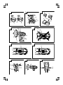 2
2
-
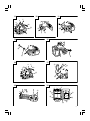 3
3
-
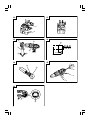 4
4
-
 5
5
-
 6
6
-
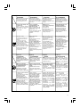 7
7
-
 8
8
-
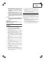 9
9
-
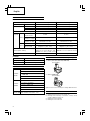 10
10
-
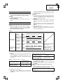 11
11
-
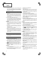 12
12
-
 13
13
-
 14
14
-
 15
15
-
 16
16
-
 17
17
-
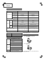 18
18
-
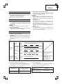 19
19
-
 20
20
-
 21
21
-
 22
22
-
 23
23
-
 24
24
-
 25
25
-
 26
26
-
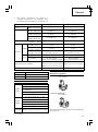 27
27
-
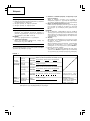 28
28
-
 29
29
-
 30
30
-
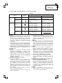 31
31
-
 32
32
-
 33
33
-
 34
34
-
 35
35
-
 36
36
-
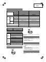 37
37
-
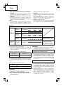 38
38
-
 39
39
-
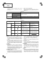 40
40
-
 41
41
-
 42
42
-
 43
43
-
 44
44
-
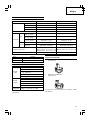 45
45
-
 46
46
-
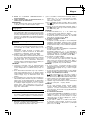 47
47
-
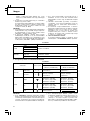 48
48
-
 49
49
-
 50
50
-
 51
51
-
 52
52
-
 53
53
-
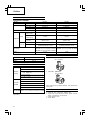 54
54
-
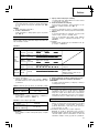 55
55
-
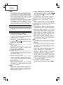 56
56
-
 57
57
-
 58
58
-
 59
59
-
 60
60
-
 61
61
-
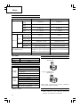 62
62
-
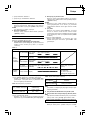 63
63
-
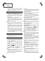 64
64
-
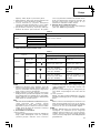 65
65
-
 66
66
-
 67
67
-
 68
68
-
 69
69
-
 70
70
-
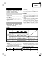 71
71
-
 72
72
-
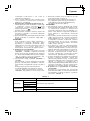 73
73
-
 74
74
-
 75
75
-
 76
76
-
 77
77
-
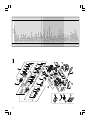 78
78
-
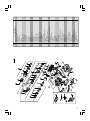 79
79
-
 80
80
-
 81
81
-
 82
82
-
 83
83
-
 84
84


Hikoki DV 14DL Kullanım kılavuzu
- Kategori
- Kablosuz kombi matkaplar
- Tip
- Kullanım kılavuzu
diğer dillerde
- slovenčina: Hikoki DV 14DL Používateľská príručka
- polski: Hikoki DV 14DL Instrukcja obsługi
İlgili makaleler
Diğer belgeler
-
Hitachi DS 18DL Handling Instructions Manual
-
Ferm CDM1112S Kullanım kılavuzu
-
-
-
Hitachi DS14DVF3 Handling Instructions Manual
-
-
-
-
-