

1

2
3
4
5

6
7
8
9

10
11
12
13

14
15

16
17

PR 30-HVSG A12
en Original operating instructions . . . . . . . . . . . . . . . . . . . . . . . . . . . . . . . . . . . . . . . 1
tr Orijinal kullanım kılavuzu . . . . . . . . . . . . . . . . . . . . . . . . . . . . . . . . . . . . . . . . . 21
ar ﺩﻟﻴﻞﺍﻻﺳﺘﻌﻤﺎﻝﺍﻷﺻﻠﻲ . . . . . . . . . . . . . . . . . . . . . . . . . . . . . . . . . . . . . . . . . . 42
lv Oriģinālā lietošanas instrukcija . . . . . . . . . . . . . . . . . . . . . . . . . . . . . . . . . . . . . 64
lt Originali naudojimo instrukcija . . . . . . . . . . . . . . . . . . . . . . . . . . . . . . . . . . . . . . 84
et Originaalkasutusjuhend . . . . . . . . . . . . . . . . . . . . . . . . . . . . . . . . . . . . . . . . . . 104
uk Оригінальна інструкція з експлуатації . . . . . . . . . . . . . . . . . . . . . . . . . . . . . . . . 124
kk Түпнұсқа пайдалану бойынша нұсқаулық . . . . . . . . . . . . . . . . . . . . . . . . . . . . . 147
ja オリジナル取扱説明書 . . . . . . . . . . . . . . . . . . . . . . . . . . . . . . . . . . . . . . . . . . . . 169
ko 오리지널 사용 설명서 . . . . . . . . . . . . . . . . . . . . . . . . . . . . . . . . . . . . . . . . . . . . . 189
cn 原版操作说明 . . . . . . . . . . . . . . . . . . . . . . . . . . . . . . . . . . . . . . . . . . . . . . . . . . 208
zh 原始操作說明 . . . . . . . . . . . . . . . . . . . . . . . . . . . . . . . . . . . . . . . . . . . . . . . . . . 227

*2179603*
2179603 English 1
Original operating instructions
1 Information about the documentation
1.1 About this documentation
• Read this documentation before initial operation or use. This is a prerequisite for safe, trouble-free
handling and use of the product.
• Observe the safety instructions and warnings in this documentation and on the product.
• Always keep the operating instructions with the product and make sure that the operating instructions
are with the product when it is given to other persons.
1.2 Explanation of symbols used
1.2.1 Warnings
Warnings alert persons to hazards that occur when handling or using the product. The following signal words
are used:
DANGER
DANGER !
▶ Draws attention to imminent danger that will lead to serious personal injury or fatality.
WARNING
WARNING !
▶ Draws attention to a potential threat of danger that can lead to serious injury or fatality.
CAUTION
CAUTION !
▶ Draws attention to a potentially dangerous situation that could lead to slight personal injury or damage
to the equipment or other property.
1.2.2 Symbols in the documentation
The following symbols are used in this document:
Read the operating instructions before use.
Instructions for use and other useful information
Dealing with recyclable materials
Do not dispose of electric equipment and batteries as household waste
1.2.3 Symbols in the illustrations
The following symbols are used in illustrations:
These numbers refer to the corresponding illustrations found at the beginning of these operating
instructions
The numbering reflects the sequence of operations shown in the illustrations and may deviate
from the steps described in the text
Item reference numbers are used in the overview illustrations and refer to the numbers used in
the product overview section
This symbol is intended to draw special attention to certain points when handling the product.

2 English 2179603
*2179603*
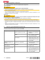
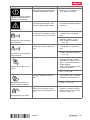
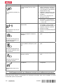
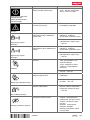
1.3 Product-dependent symbols
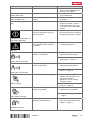
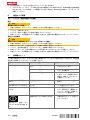
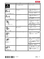
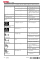
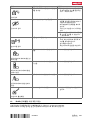
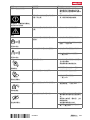
1.3.1 Symbols on the product
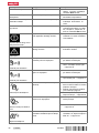
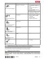
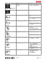
The following symbols can be used on the product:
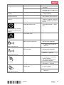
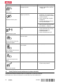
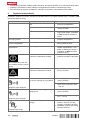
The product supports wireless data transmission compatible with iOS and Android platforms.
Hilti Li-ion battery type series used. Observe the information given in the section headed In-
tended use.
Li-ion battery
Never use the battery as a striking tool.
Do not drop the battery. Never use a battery that has suffered an impact or is damaged in any
other way.
1.4 On the product
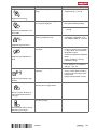
Laser information
Laser class 2 based on standard IEC60825-1 / EN60825-1:2007 and compliant with CFR
21 § 1040 (Laser Notice 50).
Do not look straight into the laser beam.
1.5 Product information
products are designed for professional users and only trained, authorized personnel are
permitted to operate, service and maintain the products. This personnel must be specifically informed about
the possible hazards. The product and its ancillary equipment can present hazards if used incorrectly by
untrained personnel or if used not in accordance with the intended use.
The type designation and serial number are printed on the rating plate.
▶ Write down the serial number in the table below. You will be required to state the product details when
contacting Hilti Service or your local Hilti organization to inquire about the product.
Product information
Rotating laser | laser receiver PR 30-HVSG A12 | PRA 30G
Generation 02
Serial no.
1.6 Declaration of conformity
We declare, on our sole responsibility, that the product described here complies with the applicable directives
and standards. A copy of the declaration of conformity can be found at the end of this documentation.
The technical documentation is filed here:
Hilti Entwicklungsgesellschaft mbH | Tool Certification | Hiltistrasse 6 | D-86916 Kaufering, Germany
1.7 Type approval test
The notified tester, CSA Group Bayern, number 1948, has tested the devices and evaluated the documents
and issued the following type approval certifications:
• PR 30HVSG A12: ZS 17 10 50140 006
• PRA 30G: ZS 17 10 50140 005
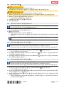
2 Safety
2.1 Basic information concerning safety
Read all safety instructions and other instructions. Failure to observe the safety instructions and other
instructions may result in electric shock, fire and/or serious injury.

*2179603*
2179603 English 3
Retain all safety precautions and instructions for future reference. The term “electric tool” used in the
safety instructions refers to your mains-operated (corded) electric tool or battery-operated (cordless) electric
tool.
2.2 General safety measures
▶ Stay alert, watch what you are doing and use common sense when operating a power tool. Do not
use a power tool while you are tired or under the influence of drugs, alcohol or medication. A moment of
inattention while operating the power tool can result in serious personal injury.
▶ Do not render safety devices ineffective and do not remove information and warning notices.
▶ Keep children well away from laser devices.
▶ Laser radiation in excess of Class 2 may be emitted if the device is opened without following the correct
procedures. Have the device repaired only by Hilti Service.
▶ Project laser beams well above or well below eye height.
▶ Take the influences of the surrounding area into account. Do not use the device where there is a
risk of fire or explosion.
▶ Statement in accordance with FCC §15.21: Changes or modifications not expressly approved by Hilti
can restrict the user’s authorization to operate the equipment.
▶ You must check the accuracy of the device after it has been dropped or subjected to other
mechanical stresses.
▶ When the device is brought into a warm environment from very cold conditions, or vice-versa,
allow it to become acclimatized before use.
▶ When using adapters or accessories, make sure that the equipment is securely mounted.
▶ Keep the laser aperture clean to avoid measurement errors.
▶ The device is designed for the tough conditions of jobsite use, but as with other optical and
electronic instruments (e.g. binoculars, spectacles, cameras) it must be handled with care.
▶ The device is protected to prevent the ingress of moisture, but you must always wipe it dry before
stowing it in the transport container.
▶ Check the device before using it for important measuring work.
▶ Repeatedly check accuracy while using the device.
▶ Make sure that the workplace is well lit.
▶ Do not expose the laser to rain or wet conditions.
▶ Do not touch the contacts.
▶ Maintain the device carefully. Check that moving parts are in full working order and do not jam
and make sure there are no parts that are broken or damaged in such a way as to impair operation
of the device. If it damaged, have the device repaired before use. Many accidents are caused by
poorly maintained equipment.
2.3 Proper preparation of the working area
▶ Secure the area in which you will be taking measurements. Make sure that the laser beam is not
directed toward other persons or toward yourself while setting up the laser tool.
▶ Avoid unfavorable body positions when working from ladders. Make sure you work from a safe
stance and stay in balance at all times.
▶ Readings taken in the vicinity of reflective objects or surfaces, through panes of glass or similar materials
may produce incorrect results.
▶ Ensure that the tool is set up on a stable, level surface (not subject to vibration).
▶ Use the tool only within its specified limits.
▶ Use the tool and its accessories etc. in accordance with these instructions and in the manner
intended for the particular type of tool. Take the working conditions and the work to be performed
into account. Use of tools for applications different from those intended could result in a hazardous
situation.
▶ Use of the telescopic staff in the vicinity of overhead high voltage cables is not permissible.
2.4 Electromagnetic compatibility
Although the tool complies with the strict requirements of the applicable directives, Hilti cannot exclude the
following possibilities:

4 English 2179603
*2179603*
• The tool may be negatively affected by powerful electromagnetic radiation, possibly leading to incorrect
operation.
In these cases, or if you are otherwise unsure, confirmatory measurements should be made by other
means.
• The tool can cause interference to other devices (e.g. aircraft navigation equipment).
2.5 Laser classification for Class 2 laser products
The tool complies with laser Class 2 as per IEC60825-1:2007 / EN60825-1:2007. This tool may be used
without need for further protective measures.
CAUTION
Risk of injury! Do not direct the laser beam toward persons.
▶ Never look directly into the source of the laser beam. In the event of direct eye contact, close your eyes
and move your head out of the path of the laser beam.
2.6 Careful use of battery-powered tools
▶ Do not expose batteries to high temperatures, the direct heat of the sun, and keep them away
from fire. There is a risk of explosion.
▶ Do not disassemble, squash or incinerate batteries and do not subject them to temperatures over
80°C (176°F). This presents a risk of fire, explosion or injury through contact with caustic substances.
▶ Do not subject the battery to hard mechanical impacts and do not throw the battery.
▶ Batteries must be kept out of reach of children.
▶ Avoid ingress of moisture. Ingress of moisture may cause a short circuit, resulting in burning injuries or
fire.
▶ Under abusive conditions, liquid may leak from the battery. Avoid contact with the liquid. If contact
accidentally occurs, flush with water. If the liquid contacts the eyes, also seek medical attention.
Liquid leaking from the battery may cause irritation or burns.
▶ Use only batteries of the type approved for use with the applicable tool. Use of other batteries or
use of the batteries for purposes for which they are not intended presents a risk of fire and explosion.
▶ Store the battery in a cool and dry place. Never store the battery where it is exposed to direct sunlight or
sources of heat, e.g. on heaters / radiators or behind glass.
▶ When not in use, keep the battery and the charger away from paper clips, coins, keys, nails,
screws or other small metal objects that could cause a short circuit at the battery terminals or the
charging contacts. Short-circuiting the contacts on a battery or charger may cause burning injuries or
start a fire.
▶ Do not charge or continue to use damaged batteries (e.g. batteries with cracks, broken parts, bent
or pushed-in and/or pulled-out contacts).
▶ Recharge only with the charger specified by the manufacturer. A charger that is suitable for a certain
type of battery may present a risk of fire when used with other types of battery.
▶ Observe the special guidelines applicable to the transport, storage and use of Li-ion batteries.
▶ The battery must be insulated or removed from the tool before the tool is shipped or sent by mail.
Leaking batteries may damage the tool.
▶ If the battery gets noticeably hot when not in use, this may indicate that the battery or the tool / battery
system is faulty. In this case, place the tool in a non-flammable location, well away from flammable
materials, where it can be kept under observation and allowed to cool down.

*2179603*
2179603 English 5
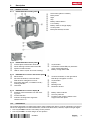
3 Description
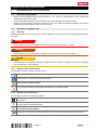
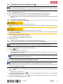
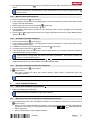
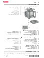
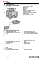
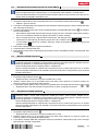
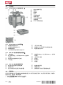
3.1 Product overview
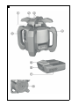
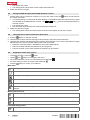
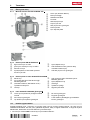
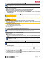
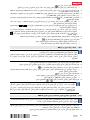
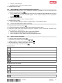
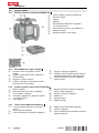
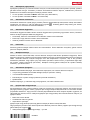
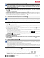
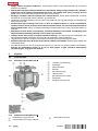
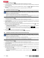
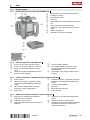
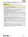
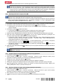
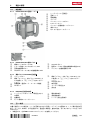
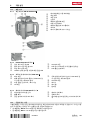
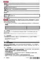
3.1.1 PR 30-HVSG A12 rotating laser 1
@
Laser beam (plane of rotation)
;
Rotary head
=
Sight
%
Grip
&
Battery release button
(
Liion battery
)
Battery state-of-charge display
+
Control panel
§
Base plate with 5/8" thread
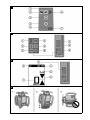
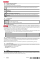
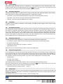
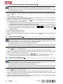
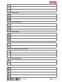
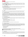
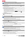
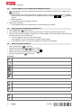
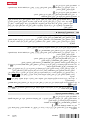
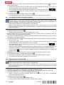
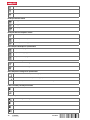
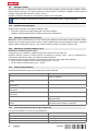
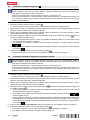
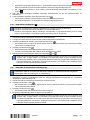
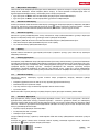
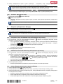
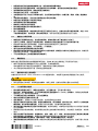
3.1.2 PR 30-HVSG A12 control panel 2
@
Inclined plane mode button and LED
;
Shock warning function button and LED
=
Speed of rotation button
%
LED for status “On/off” and “Auto-leveling”
&
On/off button
(
Surveillance mode LED (only with auto-
matic vertical alignment)
)
Battery charge status LED
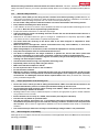
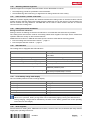
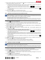
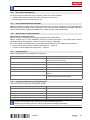
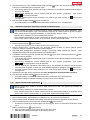
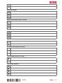
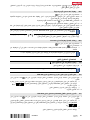
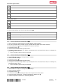
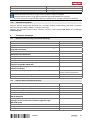
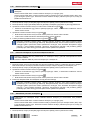
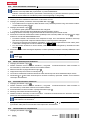
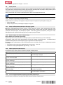
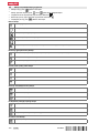
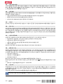
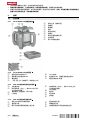
3.1.3 PRA 30G laser receiver and control panel 3
@
Menu button
;
Decrease inclination, to the left. Move
PRA 90 down. Navigation in menu.
=
Automatic alignment / surveillance mode /
marking function
%
OK button
&
Increase inclination, to the right. Move
PRA 90 up. Navigation in menu.
(
On/off button
)
Display
+
Marking notch
§
Detection window
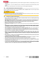
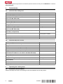
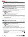
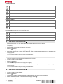
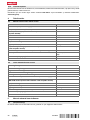
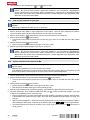
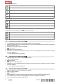
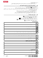
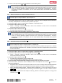
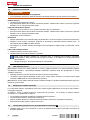
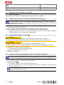
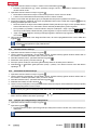
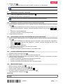
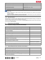
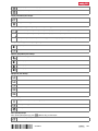
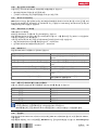
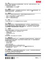
3.1.4 PRA 30G laser receiver display 4
@
Distance of the laser beam from the mark-
ing notch
;
Volume indicator
=
Indicator showing beam segments
switched off or on
%
Battery status indicator
&
Accuracy indicator
(
Position of the receiver relative to the
height of the laser plane
3.2 Intended use
The product described is a rotating laser with a visible rotating laser beam. It can be operated by one person.
The tool is designed to be used to determine, transfer and check levels, verticals, slopes and right angles.
▶ Use only the Hilti B 12⁄2.6 Li-Ion battery for this product.
▶ Use only the Hilti C 4⁄1250 charger for this product.

6 English 2179603
*2179603*
3.3 Auto-leveling
Auto-leveling takes place after the tool is switched on. LEDs indicate the current operating status. Auto-
leveling is active and can be deactivated by way of the button. The tool can be set up directly on the
ground or floor, on a tripod, or with the aid of suitable mounting brackets.
3.4 Automatic alignment
Automatic alignment allows a single person to bring the laser plane into alignment with the laser receiver.
The rotating laser tool detects the applicable direction of alignment as follows:
• Horizontal in conjunction with the PRA 90 automatic tripod and PRA 30G laser receiver.
• Inclination in the X-axis in conjunction with the PRA 30G laser receiver.
• Vertical in conjunction with the PRA 30G laser receiver.
3.5 Inclination
Inclination can be carried out manually or automatically. The PRA 79 slope adapter can be used for larger
angles of inclination.
3.6 Surveillance function
The rotating laser monitors alignment of the laser plane in conjunction with the PRA 30G laser receiver. In
the event of an alignment deviation the system corrects the direction of the laser plane, keeping it at the
zero point of the laser receiver. The rotating laser corrects all errors caused by temperature fluctuations,
wind or other such influences. If the optical connection (line of sight) between the rotating laser and the laser
receiver is interrupted for longer than two minutes, the system indicates an error. During vertical alignment,
the surveillance function can be activated only via the AUTO menu.
3.7 Automatic switch-off
The tool switches off automatically if it is unable to level itself because the rotating laser:
• Is inclined too greatly relative to the horizontal plane (except when in inclined plane mode).
• Is blocked mechanically.
• Has been knocked off level by an impact or vibration.
• Has identified a fault.
When the tool has switched itself off, rotation stops and all LEDs flash.
3.8 Shock warning function
If the rotating laser is knocked off level during operation, the built-in shock warning function switches the
tool to warning mode. The shock warning function does not go active until two minutes after completion of
auto-leveling. If a button on the control panel is pressed within this two-minute period it will take a further
two minutes for the shock warning function to go active. If the rotating laser is in warning mode:
• All LEDs flash.
• The laser stops rotating.
• The laser beam switches off.
The sensitivity of the shock warning function can be set using the PRA 30G laser receiver.
The shock warning function can be switched off by pressing the button if the ground or floor is not free
from vibration or when you are working in inclined plane mode.
▶ Deactivate the shock warning function. → page 13
3.9 Sleep mode
Sleep mode may be activated on the rotating laser during breaks between work or during other activities. All
settings concerning the laser plane or inclination are retained while in this status. Sleep mode saves power
and extends battery life.
PRA 30G the laser receiver is used to activate / deactivate sleep mode.
Sleep mode remains active for a maximum of 4 hours. The system switches itself off after this time.

*2179603*
2179603 English 7
3.10 Switching off beam segments
Individual segments of the path of the laser beam can be deactivated in order to:
• Avoid exposing yourself or bystanders to the laser beam.
• Avoid influencing other measuring or alignment work being carried out in the vicinity.
3.11 Laser receiver / remote control unit
Hilti laser receivers digitally indicate the distance between the marking notch on the laser receiver and the
position at which the laser beam (laser plane) strikes the detection area on the receiver. The laser beam can
also be received over long distances. The PRA 30G can be used as a laser receiver and also as a remote
control unit for the rotating laser.
3.12 Pairing accessories and device
Pairing accessories and device
Pairing is the act of enabling accessories and devices to communicate with each other by wireless.
The rotating laser and the laser receiver are already paired when supplied. This helps ensure trouble-free
operation within the vicinity of other wireless devices.
Additional laser receivers or PRA 90 automatic tripods cannot be used without first being paired.
▶ Pair the rotating laser and the laser receiver. → page 13
▶ Pair the tripod and laser receiver. → page 14
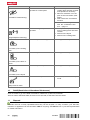
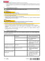
3.13 LED indicators
The rotating laser is equipped with LED indicators.
Status Meaning
All LEDs blink. The tool has been bumped, knocked off level or
has a fault.
The auto-leveling LED flashes green. The tool is in the leveling phase.
The auto-leveling LED shows steady green. The tool has leveled itself / is operating normally.
The shock warning LED shows steady orange. Shock warning mode is deactivated.
The inclination LED shows steady orange Inclined plane mode is active.
The surveillance LED flashes orange. The tool is aligning the laser plane with the
(PRA 30G) reference point.
The surveillance mode LED shows steady orange. The tool is in surveillance mode. Alignment with the
reference point (PRA 30G) is correct.
3.14 Li-ion battery charge state display
The Li-ion battery features a state of charge display.
Status Meaning
4 LEDs light. Charge status: 75 % to 100 %
3 LEDs light. Charge status: 50 % to 75 %
2 LEDs light. Charge status: 25 % to 50 %
1 LED lights. Charge status: 10 % to 25 %
1 LED blinks. Charge status: < 10 %
When the tool is in operation, the battery charge status is indicated in the display on the tool.
When not in operation, battery charge state can be indicated by lightly pressing the release button.
During charging, charge state is indicated by the LEDs on the battery (please refer to the operating
instructions for the charger).
3.15 Items supplied
PR 30-HVSG A12 rotating laser, PRA 30G laser receiver / remote control unit, 2 batteries (AA cells), PRA 54
target plate, operating instructions.

8 English 2179603
*2179603*
Other system products approved for use with this product can be found at your local Hilti Store or online at:
www.hilti.group.
4 Technical data
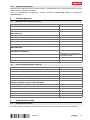
4.1 Technical data, rotating laser
PR 30-HVSG A12
Receiving range (diameter) PRA 30G
2 m … 300 m
Communication range (PRA 30G)
200 m
Accuracy at 10 m (under standard ambient conditions in accor-
dance with MILSTD810G)
±1.0 mm
Laser class
2, visible
Self-leveling range
±5°
Operating temperature
−10 ℃ … 50 ℃
Storage temperature
−25 ℃ … 60 ℃
Weight (including battery)
2.5 kg
Drop test height (under standard ambient conditions in accor-
dance with MILSTD810G)
1.5 m
Protection class in accordance with IEC 60529 (except battery
and battery compartment)
IP66
Plumb beam
Constant beam, perpendicular
to the plane of rotation
Maximum emitted transmission power
7.3 dBm
Frequency
2,400 MHz … 2,483.5 MHz
4.2 Technical data, laser receiver
Indicator range, distance from zero
±52 mm
Laser plane indication accuracy
±0.5 mm
Length of the detection area
≤ 120 mm
Center indication from top edge of casing
75 mm
Time without detection before automatic power off
15 min
Range of remote control unit (diameter) for the PR 30HVSG A12
2 m … 150 m
Drop test height in the PRA 83 laser receiver holder (under stan-
dard ambient conditions in accordance with MILSTD810G)
2 m
Operating temperature
−20 ℃ … 50 ℃
Storage temperature
−25 ℃ … 60 ℃
Weight (including batteries)
0.25 kg
Protection class in accordance with IEC 60529 (except battery
compartment)
IP66
Maximum emitted transmission power
−0.2 dBm
Frequency
2,400 MHz … 2,483.5 MHz
5 Operating the rotating laser
5.1 Preparations at the workplace
Observe the safety instructions and warnings in this documentation and on the product.

*2179603*
2179603 English 9
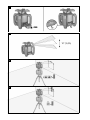
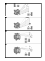
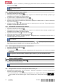
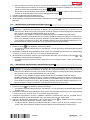
5.2 Handling the rotating laser and battery correctly 5
The B12 battery has no protection class. Do not expose the battery to rain or wet conditions.
In accordance with the Hilti instructions, the battery may be used only with the associated product
and must be inserted in the battery compartment for this purpose.
1. Fig. 1: Working in horizontal mode.
2. Fig. 2: In inclined plane mode, the rotating laser should be lifted at the control panel side.
3. Fig. 3: Laying down or transporting in an inclined position. Working in the vertical plane.
▶ Hold the rotating laser so that the battery compartment does NOT face upwards, so that no moisture
can enter.
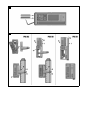
5.3 Inserting / removing the battery 6
CAUTION
Electrical hazard. Dirty contacts may cause a short circuit.
▶ Check that the contacts on the battery and on the tool are free from foreign objects before inserting the
battery.
CAUTION
Risk of injury. If the battery is not fitted correctly it may drop out and fall.
▶ Check that the battery is securely seated in the tool so that it cannot drop out and fall, thereby presenting
a hazard to other persons.
1. Push the battery in until it engages securely.
▶ The rotating laser is ready to be switched on.
2. Press the release button and hold it in this position.
3. Pull the battery out.
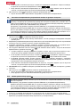
5.4 Switching the rotating laser on and working in the horizontal plane 7
Check the accuracy of the rotating laser before using it for important tasks, especially if it has been
dropped or subjected to unusual influences or impacts, or after long periods of storage.
1. Mount the rotating laser on a suitable holder or bracket.
2.
Press the button.
▶ The auto-leveling LED flashes green.
▶ As soon as the tool has leveled itself, the laser beam switches on and begins to rotate and the "auto
leveling" LED shows steadily.
A wall bracket or tripod may be used as mounting devices. The angle of inclination of the surface
on which it stands should not exceed ± 5°.
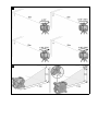
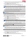
5.5 Manual horizontal alignment using the PRA 90 tripod 8
The rotating laser is mounted on the PRA 90 automatic tripod.
The PRA 30G laser receiver, the rotating laser and the PRA 90 automatic tripod are paired.
The PRA 30G laser receiver and the control panel of the PRA 90 automatic tripod are facing each
other and in direct line of sight.
1.
Press the button on the rotating laser, on the PRA 30G laser receiver and on the PRA 90 automatic
tripod.
▶ The devices are ready for use.
2.
To shift the laser plane up, press the button on the PRA 30G laser receiver or the “up” arrow button
on the PRA 90 automatic tripod.
3.
To shift the laser plane down, press the button on the PRA 30G laser receiver or the “down” arrow
button on the PRA 90 automatic tripod.

10 English 2179603
*2179603*
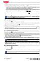
5.6 Automatic horizontal alignment using the PRA 90 tripod 9
The rotating laser is mounted on the PRA 90 automatic tripod.
The PRA 30G laser receiver, the rotating laser and the PRA 90 automatic tripod are paired.
The PRA 30G laser receiver and the control panel of the PRA 90 automatic tripod are facing each
other and in direct line of sight.
1.
Press the button on the rotating laser, on the PRA 30G laser receiver and on the PRA 90 automatic
tripod.
▶ The devices are ready for use.
2. Keep the marking notch on the PRA 30G laser receiver at the height that is to be set. The PRA 30G laser
receiver should be held steady or secured in place.
3.
Begin automatic alignment by double-clicking the button on the PRA 30G laser receiver or select the
corresponding function in the AUTO menu.
▶ The PRA 90 automatic tripod moves up and down until the correct position is reached. An signal tone
is emitted by the laser receiver repeatedly during this procedure.
▶ The rotating laser levels itself once the position has been reached. Successful completion is indicated
by a continuous signal tone with a duration of 5 seconds. The symbol is displayed briefly.
▶
If automatic alignment cannot be completed successfully, short signal tones are emitted and the
is displayed briefly.
4. Check the height setting in the display.
5. Remove the PRA 30G laser receiver.
6.
Stop automatic alignment before completion by double-clicking the button on the PRA 30G laser
receiver.
5.7 Manual vertical alignment 10
The rotating laser is placed or securely mounted in the vertical position (tripod, wall mount, facade or
batter board adapter, or lying on the rear grips). A reference point (A) is marked below the laser head
(e.g. a nail on a batter board or a spot of paint on the floor or ground).
The PRA 30G laser receiver and the rotating laser are paired.
The PRA 30G laser receiver and the receiving side of the rotating laser are facing each other and in
direct lineof sight. The best receiving side of the rotating laser is the side at which the battery is inserted.
1.
Press the button on the rotating laser.
▶ The rotating laser levels itself and then projects a stationary downward-pointing laser beam.
2. Position the rotating laser so that the projected laser beam strikes reference point (A) exactly. Please
note: The reference point is not a plumb point!
3.
To shift the laser plane to the right or left, press the or button on the PRA 30G laser receiver.
▶ The rotating laser begins rotating after pressing one of the two direction arrow buttons.
5.8 Automatic vertical alignment 11
The rotating laser is placed or securely mounted in the vertical position (tripod, wall mount, facade or
batter board adapter, or lying on the rear grips). A reference point (A) is marked below the laser head
(e.g. a nail on a batter board or a spot of paint on the floor or ground).
The PRA 30G laser receiver and the rotating laser are paired.
The PRA 30G laser receiver and the receiving side of the rotating laser are facing each other and in
direct line of sight. The best receiving side of the rotating laser is the side at which the battery is inserted.
1.
Press the button on the rotating laser.
▶ The rotating laser levels itself and then projects a stationary downward-pointing laser beam.
2. Position the rotating laser so that the projected laser beam strikes reference point (A) exactly. Please
note: The reference point is not a plumb point!
3. Keep the marking notch on the PRA 30G laser receiver on the plane that is to be set. The PRA 30G laser
receiver should be held steady or secured in place.

*2179603*
2179603 English 11
4.
Begin automatic alignment by double-clicking the button on the PRA 30G laser receiver or select the
corresponding function in the AUTO menu.
▶ The head of the rotating laser pivots to the left and right until the position is reached. An signal tone
is emitted by the laser receiver repeatedly during this procedure.
▶
The rotating laser levels itself once the position has been reached. The symbol is displayed
briefly.
▶
If automatic alignment cannot be completed successfully, short signal tones are emitted and the
is displayed briefly.
5.
Double-click the button on the PRA 30G laser receiver.
▶ During automatic alignment: Stops automatic alignment before completion.
5.9 Automatic vertical alignment with surveillance function
The rotating laser is placed or securely mounted in the vertical position (tripod, wall mount, facade or
batter board adapter, or lying on the rear grips). A reference point (A) is marked below the laser head
(e.g. a nail on a batter board or a spot of paint on the floor or ground).
The PRA 30G laser receiver and the rotating laser are paired.
The PRA 30G laser receiver and the receiving side of the rotating laser are facing each other and in
direct line of sight. The best receiving side of the rotating laser is the side at which the battery is inserted.
1.
Press the button on the rotating laser.
▶ The rotating laser levels itself and then projects a stationary downward-pointing laser beam.
2. Position the rotating laser so that the projected laser beam strikes reference point (A) exactly. Please
note: The reference point is not a plumb point!
3. Keep the marking notch on the PRA 30G laser receiver on the plane that is to be set. The PRA 30G laser
receiver should be held steady or secured in place.
4.
Press the button on the PRA 30G to display the AUTO menu. Start automatic alignment with
surveillance function .
▶ The head of the rotating laser pivots to the left and right until the position is reached. An signal tone
is emitted by the laser receiver repeatedly during this procedure.
▶
The rotating laser levels itself once the position has been reached. The symbol is displayed
briefly and the signal tone stops.
▶ The rotating laser switches to the surveillance function. Small deviations due to external influences
are then compensated automatically and the laser beam is kept at the height of the marking notch on
the laser receiver.
▶
If automatic alignment cannot be completed successfully, short signal tones are emitted and the
is displayed briefly.
5. Do NOT remove the PRA 30G laser receiver from the target plane so long as surveillance mode is active.
6.
Double-click the button on the PRA 30G laser receiver.
▶ During automatic alignment: Stops automatic alignment before completion.
▶ If the surveillance function is active: Deactivate (end) the surveillance function.
5.10 Setting the inclination manually 12
The rotating laser, depending on the application, is mounted or positioned securely.
The PRA 30G laser receiver and the rotating laser are paired.
The PRA 30G laser receiver and the receiving side of the rotating laser are facing each other and in
direct line of sight. The best receiving side of the rotating laser is the side at which the battery is inserted.
1. Position the rotating laser either at the upper edge or lower edge of the inclined plane.
2. Use the target sight on the head of the tool to align the rotating laser parallel to the inclined plane.
3.
Press the button on the rotating laser and the PRA 30G laser receiver.
▶ The laser switches on, the beam begins to rotate and the “auto leveling” LED lights as soon as the
tool has leveled itself.
4.
Press the button on the rotating laser.
▶ The inclined plane mode LED on the rotating laser lights constantly.
▶ The inclined plane mode symbol is shown on the PRA 30G laser receiver.

12 English 2179603
*2179603*
5.
Use the or buttons on the laser receiver to incline the laser plane.
When the angle of inclination is set manually, the rotating laser levels the laser plane once and
then fixes it once. Note that this rotating laser does not correct the sloped laser plane for possible
deviation occurring due to a change in ambient conditions and/or shift of the mounting. Vibration,
changes in temperature or other influences that may occur during the course of the day may affect
the position of the laser plane.
5.11 Setting the inclination using the PRA 79 slope adapter
Depending on the application, the PRA 79 slope adapter can be mounted on a tripod or on a wall
bracket.
The angle of inclination of the PRA 79 slope adapter is set to 0°.
1. Mount the rotating laser on the PRA 79 slope adapter. Observe the operating instructions for the PRA 79
slope adapter. The control panel of the rotating laser should be facing you.
2. Position the rotating laser either at the upper edge or lower edge of the inclined plane.
3.
Press the button on the rotating laser.
▶ The laser switches on, the beam begins to rotate and the “auto leveling” LED lights as soon as the
tool has leveled itself.
4.
Press the button on the rotating laser.
▶ The inclined plane mode LED on the rotating laser lights constantly.
5. Set the PRA 79 slope adapter to the desired angle of inclination.
When the angle of inclination is set manually, the rotating laser levels the laser plane once and
then fixes it once. Note that this rotating laser does not correct the sloped laser plane for possible
deviation occurring due to a change in ambient conditions and/or shift of the mounting. Vibration,
changes in temperature or other influences that may occur during the course of the day may affect
the position of the laser plane.
5.12 Setting inclination automatically 13
The rotating laser, depending on the application, is mounted or positioned securely.
The PRA 30G laser receiver and the rotating laser are paired.
The PRA 30G laser receiver and the receiving side of the rotating laser are facing each other and in
direct line of sight. The best receiving side of the rotating laser is the side at which the battery is inserted.
1. Position the rotating laser either at the upper edge or lower edge of the inclined plane.
2.
Press the button on the rotating laser and the PRA 30G laser receiver.
▶ The laser switches on, the beam begins to rotate and the “auto leveling” LED lights as soon as the
tool has leveled itself.
3.
Press the button on the rotating laser.
▶ The inclined plane mode LED on the rotating laser lights constantly.
▶ The inclined plane mode symbol is shown on the PRA 30G laser receiver.
4. Position the marking notch on the PRA 30G laser receiver at the other edge of the inclined plane.
5.
Begin automatic alignment by double-clicking the button on the PRA 30G laser receiver or select the
corresponding function in the AUTO menu.
▶ The rotating laser inclines the laser plane on the X-axis automatically until the mark at the PRA 30G
laser receiver is reached. An signal tone is emitted by the laser receiver repeatedly during this
procedure.
▶ The rotating laser levels itself on the Y-axis once the position has been reached. Successful
completion is indicated by a continuous signal tone with a duration of 5 seconds. The
symbol is displayed briefly.
▶
If automatic alignment cannot be completed successfully, short signal tones are emitted and the
is displayed briefly.
Sayfa yükleniyor ...
Sayfa yükleniyor ...
Sayfa yükleniyor ...
Sayfa yükleniyor ...
Sayfa yükleniyor ...
Sayfa yükleniyor ...
Sayfa yükleniyor ...
Sayfa yükleniyor ...
Sayfa yükleniyor ...
Sayfa yükleniyor ...
Sayfa yükleniyor ...
Sayfa yükleniyor ...
Sayfa yükleniyor ...
Sayfa yükleniyor ...
Sayfa yükleniyor ...
Sayfa yükleniyor ...
Sayfa yükleniyor ...
Sayfa yükleniyor ...
Sayfa yükleniyor ...
Sayfa yükleniyor ...
Sayfa yükleniyor ...
Sayfa yükleniyor ...
Sayfa yükleniyor ...
Sayfa yükleniyor ...
Sayfa yükleniyor ...
Sayfa yükleniyor ...
Sayfa yükleniyor ...
Sayfa yükleniyor ...
Sayfa yükleniyor ...
Sayfa yükleniyor ...
Sayfa yükleniyor ...
Sayfa yükleniyor ...
Sayfa yükleniyor ...
Sayfa yükleniyor ...
Sayfa yükleniyor ...
Sayfa yükleniyor ...
Sayfa yükleniyor ...
Sayfa yükleniyor ...
Sayfa yükleniyor ...
Sayfa yükleniyor ...
Sayfa yükleniyor ...
Sayfa yükleniyor ...
Sayfa yükleniyor ...
Sayfa yükleniyor ...
Sayfa yükleniyor ...
Sayfa yükleniyor ...
Sayfa yükleniyor ...
Sayfa yükleniyor ...
Sayfa yükleniyor ...
Sayfa yükleniyor ...
Sayfa yükleniyor ...
Sayfa yükleniyor ...
Sayfa yükleniyor ...
Sayfa yükleniyor ...
Sayfa yükleniyor ...
Sayfa yükleniyor ...
Sayfa yükleniyor ...
Sayfa yükleniyor ...
Sayfa yükleniyor ...
Sayfa yükleniyor ...
Sayfa yükleniyor ...
Sayfa yükleniyor ...
Sayfa yükleniyor ...
Sayfa yükleniyor ...
Sayfa yükleniyor ...
Sayfa yükleniyor ...
Sayfa yükleniyor ...
Sayfa yükleniyor ...
Sayfa yükleniyor ...
Sayfa yükleniyor ...
Sayfa yükleniyor ...
Sayfa yükleniyor ...
Sayfa yükleniyor ...
Sayfa yükleniyor ...
Sayfa yükleniyor ...
Sayfa yükleniyor ...
Sayfa yükleniyor ...
Sayfa yükleniyor ...
Sayfa yükleniyor ...
Sayfa yükleniyor ...
Sayfa yükleniyor ...
Sayfa yükleniyor ...
Sayfa yükleniyor ...
Sayfa yükleniyor ...
Sayfa yükleniyor ...
Sayfa yükleniyor ...
Sayfa yükleniyor ...
Sayfa yükleniyor ...
Sayfa yükleniyor ...
Sayfa yükleniyor ...
Sayfa yükleniyor ...
Sayfa yükleniyor ...
Sayfa yükleniyor ...
Sayfa yükleniyor ...
Sayfa yükleniyor ...
Sayfa yükleniyor ...
Sayfa yükleniyor ...
Sayfa yükleniyor ...
Sayfa yükleniyor ...
Sayfa yükleniyor ...
Sayfa yükleniyor ...
Sayfa yükleniyor ...
Sayfa yükleniyor ...
Sayfa yükleniyor ...
Sayfa yükleniyor ...
Sayfa yükleniyor ...
Sayfa yükleniyor ...
Sayfa yükleniyor ...
Sayfa yükleniyor ...
Sayfa yükleniyor ...
Sayfa yükleniyor ...
Sayfa yükleniyor ...
Sayfa yükleniyor ...
Sayfa yükleniyor ...
Sayfa yükleniyor ...
Sayfa yükleniyor ...
Sayfa yükleniyor ...
Sayfa yükleniyor ...
Sayfa yükleniyor ...
Sayfa yükleniyor ...
Sayfa yükleniyor ...
Sayfa yükleniyor ...
Sayfa yükleniyor ...
Sayfa yükleniyor ...
Sayfa yükleniyor ...
Sayfa yükleniyor ...
Sayfa yükleniyor ...
Sayfa yükleniyor ...
Sayfa yükleniyor ...
Sayfa yükleniyor ...
Sayfa yükleniyor ...
Sayfa yükleniyor ...
Sayfa yükleniyor ...
Sayfa yükleniyor ...
Sayfa yükleniyor ...
Sayfa yükleniyor ...
Sayfa yükleniyor ...
Sayfa yükleniyor ...
Sayfa yükleniyor ...
Sayfa yükleniyor ...
Sayfa yükleniyor ...
Sayfa yükleniyor ...
Sayfa yükleniyor ...
Sayfa yükleniyor ...
Sayfa yükleniyor ...
Sayfa yükleniyor ...
Sayfa yükleniyor ...
Sayfa yükleniyor ...
Sayfa yükleniyor ...
Sayfa yükleniyor ...
Sayfa yükleniyor ...
Sayfa yükleniyor ...
Sayfa yükleniyor ...
Sayfa yükleniyor ...
Sayfa yükleniyor ...
Sayfa yükleniyor ...
Sayfa yükleniyor ...
Sayfa yükleniyor ...
Sayfa yükleniyor ...
Sayfa yükleniyor ...
Sayfa yükleniyor ...
Sayfa yükleniyor ...
Sayfa yükleniyor ...
Sayfa yükleniyor ...
Sayfa yükleniyor ...
Sayfa yükleniyor ...
Sayfa yükleniyor ...
Sayfa yükleniyor ...
Sayfa yükleniyor ...
Sayfa yükleniyor ...
Sayfa yükleniyor ...
Sayfa yükleniyor ...
Sayfa yükleniyor ...
Sayfa yükleniyor ...
Sayfa yükleniyor ...
Sayfa yükleniyor ...
Sayfa yükleniyor ...
Sayfa yükleniyor ...
Sayfa yükleniyor ...
Sayfa yükleniyor ...
Sayfa yükleniyor ...
Sayfa yükleniyor ...
Sayfa yükleniyor ...
Sayfa yükleniyor ...
Sayfa yükleniyor ...
Sayfa yükleniyor ...
Sayfa yükleniyor ...
Sayfa yükleniyor ...
Sayfa yükleniyor ...
Sayfa yükleniyor ...
Sayfa yükleniyor ...
Sayfa yükleniyor ...
Sayfa yükleniyor ...
Sayfa yükleniyor ...
Sayfa yükleniyor ...
Sayfa yükleniyor ...
Sayfa yükleniyor ...
Sayfa yükleniyor ...
Sayfa yükleniyor ...
Sayfa yükleniyor ...
Sayfa yükleniyor ...
Sayfa yükleniyor ...
Sayfa yükleniyor ...
Sayfa yükleniyor ...
Sayfa yükleniyor ...
Sayfa yükleniyor ...
Sayfa yükleniyor ...
Sayfa yükleniyor ...
Sayfa yükleniyor ...
Sayfa yükleniyor ...
Sayfa yükleniyor ...
Sayfa yükleniyor ...
Sayfa yükleniyor ...
Sayfa yükleniyor ...
Sayfa yükleniyor ...
Sayfa yükleniyor ...
Sayfa yükleniyor ...
Sayfa yükleniyor ...
Sayfa yükleniyor ...
Sayfa yükleniyor ...
Sayfa yükleniyor ...
Sayfa yükleniyor ...
Sayfa yükleniyor ...
Sayfa yükleniyor ...
Sayfa yükleniyor ...
Sayfa yükleniyor ...
Sayfa yükleniyor ...
Sayfa yükleniyor ...
Sayfa yükleniyor ...
Sayfa yükleniyor ...
Sayfa yükleniyor ...
Sayfa yükleniyor ...
Sayfa yükleniyor ...
Sayfa yükleniyor ...
Sayfa yükleniyor ...
Sayfa yükleniyor ...
Sayfa yükleniyor ...
Sayfa yükleniyor ...
Sayfa yükleniyor ...
Sayfa yükleniyor ...
-
 1
1
-
 2
2
-
 3
3
-
 4
4
-
 5
5
-
 6
6
-
 7
7
-
 8
8
-
 9
9
-
 10
10
-
 11
11
-
 12
12
-
 13
13
-
 14
14
-
 15
15
-
 16
16
-
 17
17
-
 18
18
-
 19
19
-
 20
20
-
 21
21
-
 22
22
-
 23
23
-
 24
24
-
 25
25
-
 26
26
-
 27
27
-
 28
28
-
 29
29
-
 30
30
-
 31
31
-
 32
32
-
 33
33
-
 34
34
-
 35
35
-
 36
36
-
 37
37
-
 38
38
-
 39
39
-
 40
40
-
 41
41
-
 42
42
-
 43
43
-
 44
44
-
 45
45
-
 46
46
-
 47
47
-
 48
48
-
 49
49
-
 50
50
-
 51
51
-
 52
52
-
 53
53
-
 54
54
-
 55
55
-
 56
56
-
 57
57
-
 58
58
-
 59
59
-
 60
60
-
 61
61
-
 62
62
-
 63
63
-
 64
64
-
 65
65
-
 66
66
-
 67
67
-
 68
68
-
 69
69
-
 70
70
-
 71
71
-
 72
72
-
 73
73
-
 74
74
-
 75
75
-
 76
76
-
 77
77
-
 78
78
-
 79
79
-
 80
80
-
 81
81
-
 82
82
-
 83
83
-
 84
84
-
 85
85
-
 86
86
-
 87
87
-
 88
88
-
 89
89
-
 90
90
-
 91
91
-
 92
92
-
 93
93
-
 94
94
-
 95
95
-
 96
96
-
 97
97
-
 98
98
-
 99
99
-
 100
100
-
 101
101
-
 102
102
-
 103
103
-
 104
104
-
 105
105
-
 106
106
-
 107
107
-
 108
108
-
 109
109
-
 110
110
-
 111
111
-
 112
112
-
 113
113
-
 114
114
-
 115
115
-
 116
116
-
 117
117
-
 118
118
-
 119
119
-
 120
120
-
 121
121
-
 122
122
-
 123
123
-
 124
124
-
 125
125
-
 126
126
-
 127
127
-
 128
128
-
 129
129
-
 130
130
-
 131
131
-
 132
132
-
 133
133
-
 134
134
-
 135
135
-
 136
136
-
 137
137
-
 138
138
-
 139
139
-
 140
140
-
 141
141
-
 142
142
-
 143
143
-
 144
144
-
 145
145
-
 146
146
-
 147
147
-
 148
148
-
 149
149
-
 150
150
-
 151
151
-
 152
152
-
 153
153
-
 154
154
-
 155
155
-
 156
156
-
 157
157
-
 158
158
-
 159
159
-
 160
160
-
 161
161
-
 162
162
-
 163
163
-
 164
164
-
 165
165
-
 166
166
-
 167
167
-
 168
168
-
 169
169
-
 170
170
-
 171
171
-
 172
172
-
 173
173
-
 174
174
-
 175
175
-
 176
176
-
 177
177
-
 178
178
-
 179
179
-
 180
180
-
 181
181
-
 182
182
-
 183
183
-
 184
184
-
 185
185
-
 186
186
-
 187
187
-
 188
188
-
 189
189
-
 190
190
-
 191
191
-
 192
192
-
 193
193
-
 194
194
-
 195
195
-
 196
196
-
 197
197
-
 198
198
-
 199
199
-
 200
200
-
 201
201
-
 202
202
-
 203
203
-
 204
204
-
 205
205
-
 206
206
-
 207
207
-
 208
208
-
 209
209
-
 210
210
-
 211
211
-
 212
212
-
 213
213
-
 214
214
-
 215
215
-
 216
216
-
 217
217
-
 218
218
-
 219
219
-
 220
220
-
 221
221
-
 222
222
-
 223
223
-
 224
224
-
 225
225
-
 226
226
-
 227
227
-
 228
228
-
 229
229
-
 230
230
-
 231
231
-
 232
232
-
 233
233
-
 234
234
-
 235
235
-
 236
236
-
 237
237
-
 238
238
-
 239
239
-
 240
240
-
 241
241
-
 242
242
-
 243
243
-
 244
244
-
 245
245
-
 246
246
-
 247
247
-
 248
248
-
 249
249
-
 250
250
-
 251
251
-
 252
252
-
 253
253
-
 254
254
-
 255
255
-
 256
256
-
 257
257
-
 258
258
-
 259
259
-
 260
260


Diğer dillerde
İlgili Makaleler
-
Hilti PR 3-HVSG A12 Kullanım kılavuzu
-
-
Hilti PR 3-HVSG Kullanma talimatları
-
-
-
Hilti PR 30 Kullanma talimatları
-
Hilti PRI 36 Kullanma talimatları
-
-
-
Hilti PMC 46 Kullanma talimatları