
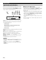
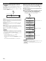
DSP-AZ1
AV Amplifier
Amplificateur Audio-Video
OWNER’S MANUAL
MODE D’EMPLOI
BEDIENUNGSANLEITUNG
G
STANDBY
/ON
INPUT MODE
INPUT SELECTOR
VOLUME
SPEAKERS
BASS
SILENT
PHONES
A B
NEXT
PROCESSOR
DIRECT
BASS
EXTENSION
6CH
INPUT
STEREO
EFFECT
ON
S VIDEO VIDEO
OFF
LR
PHONO
CD
TUNER
CD–R
MD/TAPE
DVD
SOURCE/REMOTE
D–TV/LD
CABLE
SAT
VCR 1
VCR 2
VCR 3/DVR
VIDEO AUX
SET MENU
TREBLE
VIDEO AUX
L AUDIO
OPTICAL
R
PROGRAM
BALANCE
REC OUT/ZONE 2

CAUTION
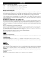
CAUTION: READ THIS BEFORE OPERATING YOUR UNIT.
1 To assure the finest performance, please read this manual
carefully. Keep it in a safe place for future reference.
2 Install this unit in a well ventilated, cool, dry, clean place with at
least 30 cm on the top, 10 cm on the right and left, and 10 cm at
the back of this unit — away from direct sunlight, heat sources,
vibration, dust, moisture, and/or cold.
3 Locate this unit away from other electrical appliances, motors,
or transformers to avoid humming sounds. To prevent fire or
electrical shock, do not place this unit where it may get exposed
to rain, water, and/or any type of liquid.
4 Do not expose this unit to sudden temperature changes from
cold to hot, and do not locate this unit in a environment with
high humidity (i.e. a room with a humidifier) to prevent
condensation inside this unit, which may cause an electrical
shock, fire, damage to this unit, and/or personal injury.
5 On the top of this unit, do not place:
– Other components, as they may cause damage and/or discolora-
tion on the surface of this unit.
– Burning objects (i.e. candles), as they may cause fire, damage
to this unit, and/or personal injury.
– Containers with liquid in them, as they may cause electrical
shock to the user and/or damage to this unit.
6 Do not cover this unit with a newspaper, tablecloth, curtain, etc.
in order not to obstruct heat radiation. If the temperature inside
this unit rises, it may cause fire, damage to this unit, and/or
personal injury.
7 Do not plug in this unit to a wall outlet until all connections are
complete.
8 Do not operate this unit upside-down. It may overheat, possibly
causing damage.
9 Do not use force on switches, knobs and/or cords.
10 When disconnecting the power cord from the wall outlet, grasp
the plug; do not pull the cord.
11 Do not clean this unit with chemical solvents; this might
damage the finish. Use a clean, dry cloth.
12 Only voltage specified on this unit must be used. Using this unit
with a higher voltage than specified is dangerous and may cause
fire, damage to this unit, and/or personal injury. YAMAHA will
not be held responsible for any damage resulting from use of
this unit with a voltage other than specified.
13 To prevent damage by lightning, disconnect the power cord
from the wall outlet during an electrical storm.
14 Take care of this unit so that no foreign objects and/or liquid
drops inside this unit.
15 Do not attempt to modify or fix this unit. Contact qualified
YAMAHA service personnel when any service is needed. The
cabinet should never be opened for any reasons.
16 When not planning to use this unit for long periods of time (i.e.
vacation), disconnect the AC power plug from the wall outlet.
17 Be sure to read the “TROUBLESHOOTING” section on
common operating errors before concluding that this unit is
faulty.
18 Before moving this unit, press STANDBY/ON to set this unit in
the standby mode, and disconnect the AC power plug from the
wall outlet.
19 VOLTAGE SELECTOR (China and General models only)
The VOLTAGE SELECTOR on the rear panel of this unit must
be set for your local main voltage BEFORE plugging into the
AC main supply.
Voltages are 110/120/220/240 V AC, 50/60 Hz.
This unit is not disconnected from the AC power source as long
as it is connected to the wall outlet, even if this unit itself is
turned off. This state is called the standby mode. In this state,
this unit is designed to consume a very small quantity of power.
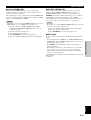
■ For U.K. customers
If the socket outlets in the home are not suitable for the plug
supplied with this appliance, it should be cut off and an appropriate
3 pin plug fitted. For details, refer to the instructions described
below.
Note
• The plug severed from the mains lead must be destroyed, as a plug
with bared flexible cord is hazardous if engaged in a live socket
outlet.
■ Special Instructions for U.K. Model
IMPORTANT
THE WIRES IN MAINS LEAD ARE COLOURED IN
ACCORDANCE WITH THE FOLLOWING CODE:
Blue: NEUTRAL
Brown: LIVE
As the colours of the wires in the mains lead of this apparatus
may not correspond with the coloured markings identifying the
terminals in your plug, proceed as follows:
The wire which is coloured BLUE must be connected to the
terminal which is marked with the letter N or coloured BLACK.
The wire which is coloured BROWN must be connected to the
terminal which is marked with the letter L or coloured RED.
Making sure that neither core is connected to the earth terminal
of the three pin plug.

INTRODUCTION
English
E-1
PREPARATIONS
BASIC OPERATIONS
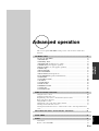
ADVANCED
OPERATION
SOUND FIELD
PROGRAMS
APPENDIX
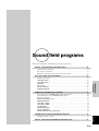
Contents
Contents
INTRODUCTION 3
Features ......................................................................................................................... 4
Controls and functions .................................................................................................. 6
PREPARATIONS 13
Speaker system configurations ................................................................................... 14
Speaker placement ...................................................................................................... 16
Connections ................................................................................................................ 18
On-screen displays (OSD) .......................................................................................... 33
Speaker mode settings ................................................................................................ 34
Speaker output levels .................................................................................................. 38
BASIC OPERATIONS 41
Basic playback ............................................................................................................ 42
Basic recording ........................................................................................................... 50
ADVANCED OPERATION 51
Set menu items ............................................................................................................ 52
Remote control features .............................................................................................. 64
Adjusting the levels of the effect speakers .................................................................. 81
Sleep timer .................................................................................................................. 82
Zone 2 ......................................................................................................................... 83
SOUND FIELD PROGRAMS 85
Digital sound field processing (DSP) ......................................................................... 86
Hi-Fi DSP-sound field program .................................................................................. 88
CINEMA-DSP sound field program ........................................................................... 90
Sound field program parameter editing ...................................................................... 95
Digital sound field parameter descriptions ................................................................. 96
APPENDIX 101
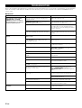
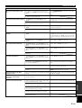
Troubleshooting ........................................................................................................ 102
CINEMA EQ frequency characteristics.................................................................... 105
Reference chart for the input and output jacks ......................................................... 106
Specifications ............................................................................................................ 107

E-2
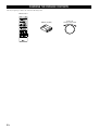
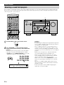
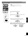
CHECKING THE PACKAGE CONTENTS
Check your package to make sure it has the following items.
PUSH
TRANSMIT RE–NAME
CLEAR LEARN MACRO OFF ON
MACRO
SYSTEM
POWER
STANDBY
V–AUX TUNER PHONO
CABLE SAT MD/TAPE CD–R CD
D–TV/LD VCR 1 VCR 2 VCR3/DVR DVD
6CH INPUT
TITLE
DISPLAY
MENU
SOUND
ENTER
SOURCE
SEARCH
POWER STOP PAUSE PLAYREC
CHAPTER
SELECT
10KEY DSP
1
HALL 1
2
HALL 2
3
CHURCH
4
5678
JAZZ CLUB
0
CHP/INDEX
+
10
+
100
ROCK
CONCERT
ENTER–
TAINMENT
CONCERT
VIDEO 1
CONCERT
VIDEO 2
9101112
TV
THEATER
EX/ES
MOVIE
THEATER 1
MOVIE
THEATER 2
/DTS
SUR.
TV VOL CH
VOLUME
DISC
PRESET
A/B/C/D/E
TV MUTE
TV INPUT
MUTE
EFFECT
STEREO
ON SCREEN
SLEEP
LEVEL
TEST
SET MENU
PARAMETER
Remote control
Batteries (3) (LR6)
Power cord
(except for U.K. model)

E-3
INTRODUCTION
English
Introduction
Introduction
This section describes the features of the DSP-AZ1, and its controls and functions.
FEATURES ........................................................................................................... 4
CONTROLS AND FUNCTIONS............................................................................ 6
Front panel .................................................................................................................... 6
Remote control .............................................................................................................. 8
Front panel display ...................................................................................................... 11
Rear panel ................................................................................................................... 12

E-4
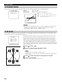
FEATURES
■ Built-in 8-channel power amplifier
• Main: 130 W + 130 W (8Ω) RMS Output Power, 0.015% THD, 20 – 20,000 Hz
• Center: 130 W (8Ω) RMS Output Power, 0.015% THD, 20 – 20,000 Hz
• Rear: 130 W + 130 W (8Ω) RMS Output Power, 0.015% THD, 20 – 20,000 Hz
• Front: 45 W + 45 W (8Ω) RMS Output Power, 0.05% THD, 1 kHz
• Rear center: 130 W (8Ω) RMS Output Power, 0.015% THD, 20 – 20,000 Hz
■ Digital Sound Fields (DSP)
Technological advances in sound reproduction over the last 30 years have enhanced the listening experience with improved clarity, precision,
and power. However, something has been missing: the atmosphere and acoustic ambience of the public venue. Our Yamaha engineers have
extensively researched the nature of sound acoustics and the way sound reflects inside a room. We sent these engineers to famous theaters
and concert halls around the world to measure the acoustics of those venues with sophisticated microphones. The data they collected is used
to recreate these environments in digital sound fields. Some of these digital sound fields have been created using data measured at the
original venue; others have been created from combinations of data to form unique environments for specific purposes. Some have been
designed especially for music, and others especially for movies. Of course, this only solves half of the problem. Because these engineers have
no way of knowing the acoustics of your entertainment room, we have made it possible for you to adjust the various parameters of this data
to tailor each virtual venue to your taste. You can use these sound fields to enhance any source and in combination with any of the following
surround sound technologies.
■ CINEMA-DSP: Dolby Digital + DSP and DTS + DSP
The Dolby Digital system and DTS system show their full capability in large movie theaters, because feature film soundtracks are designed
to be reproduced in such environments. It is difficult to recreate a sound environment similar to a movie theater in your entertainment room
because of the room size, wall materials, and the number of speakers in your entertainment system. Yamaha DSP technology makes it
possible for you to enjoy nearly the same sound experience as that of a large movie theater in your entertainment room by compensating for
lack of presence and dynamics in your entertainment room with Yamaha's original digital sound fields combined with Dolby Digital or DTS
soundtracks.
■ Virtual CINEMA DSP and SILENT CINEMA DSP
Yamaha developed the Virtual CINEMA DSP algorithm which allows you to experience the virtual sound fields without surround speakers.
This makes it possible for the DSP-AZ1 to produce a full surround sound catering to the number of speakers you have. The DSP-AZ1 also
has a SILENT CINEMA DSP algorithm which is achieved by the crosstalk processing applying the precise Head Related Transfer Function.
You can therefore enjoy listening to the CINEMA DSP soundfields on headphones.
■ Various decoders to support the newest sound effect technology
This unit is equipped with the following signal format decoders.
• Dolby Digital and Dolby Digital EX
The Matrix decoder enables 6.1-channel playback of the 5.1-channel sources by extracting the rear center channel signals from the rear L/R
channel signals.
• DOLBY PRO LOGIC
• DOLBY PRO LOGIC
DOLBY PRO LOGIC is the improved technique to decode vast numbers of existing Dolby Surround programs. This new technology
enables a discrete 5-channel playback with two left and right main channels, a center channel, and two left and right rear channels compared
with one limited rear channel for the conventional Pro Logic technology. Also the music mode is available for 2-channel sources in addition
to the movie mode.
• DTS and DTS ES
The DSP-AZ1 is also equipped with a DTS decoder, which uses a 5.1-channel system to create a full surround sound environment. It was
developed as a way to replace the analog soundtracks of movies with six channels of digital sound. In comparison with Dolby Digital, DTS
uses less compression to store the sound information. The newly presented DTS ES system reproduces digital sound similar to Dolby Digital
EX. The use of the rear center speaker along with the existing 5.1-channel speakers provides a fully immersive cinematic audio experience.
• DTS Neo: 6
Neo: 6 decodes the conventional 2-channel sources for 6-channel playback by the specific decoder. It enables playback with the full-range
channels with higher separation just like digital discrete signal playback. Two modes are available; “Music mode” for playing music sources
and “Cinema mode” for movies.
• DTS 96/24
DTS 96/24 achieves the high quality playback with all 5.1 channels at the sampling frequency 96 kHz/24 bit.

E-5
INTRODUCTION
English
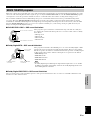
■ Various input and output jacks
The DSP-AZ1 has various output jacks for audio and video signals as well as a digital recording output jack. Many input jacks are also
available for connection to multiple audio-video sources. All the video inputs and outputs have S-video jacks in addition to standard
composite video jacks for improved video picture quality. Component video input and output jacks are also available to deliver the excellent
video signals from DVD players and other high quality video sources. The coaxial and optical digital signal jacks (provided for direct
transmission of digital signals) automatically detect Dolby Digital, DTS, and PCM signals. A demodulator circuit is built into the Dolby
Digital RF input so you can connect it directly to the Dolby Digital RF signal output on your LD player. Additionally, there are six audio
inputs for discrete multichannel reproduction from an external decoder.
The DSP-AZ1 also comes with a monaural subwoofer jack and split subwoofer jacks which can reproduce delicate but powerful low
frequency effects.
■ Multi-function remote control
The remote control can operate other audio-video components once you program the remote control using the manufacturer code and Learn
feature.
FEATURES
Manufactured under license from Dolby Laboratories.
“Dolby”, “Pro Logic”, and the double-D symbol are trademarks of Dolby Laboratories.
“DTS”, “DTS-ES Extended Surround” and “Neo: 6” are trademarks of Digital Theater System, Inc.

E-6
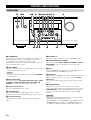
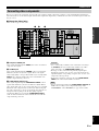
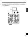
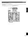
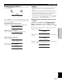
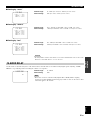
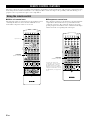
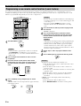
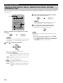
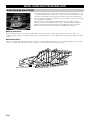
CONTROLS AND FUNCTIONS
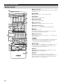
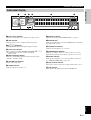
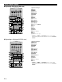
Front panel
STANDBY
/ON
INPUT MODE
INPUT SELECTOR
VOLUME
SPEAKERS
BASS
SILENT
PHONES
A B
NEXT
PROCESSOR
DIRECT
BASS
EXTENSION
6CH
INPUT
STEREO
EFFECT
ON
S VIDEO VIDEO
OFF
LR
PHONO
CD
TUNER
CD–R
MD/TAPE
DVD
SOURCE/REMOTE
D–TV/LD
CABLE
SAT
VCR 1
VCR 2
VCR 3/DVR
VIDEO AUX
SET MENU
TREBLE
VIDEO AUX
L AUDIO
OPTICAL
R
BALANCE
REC OUT/ZONE 2
PROGRAM
123 4567890qwer t
yui o p
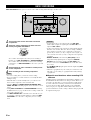
1 STANDBY/ON
Turns this unit on (On mode) and off (Standby mode). When you
turn on this unit, you will hear a click and there will be a 4 to
5-second delay before this unit can reproduce sound.
In Standby mode, this unit consumes a small amount of power so it
can respond to the remote control.
2 INPUT MODE
Selects the mode of input for sources that output two or more types
of signals to this unit (see page 44).
Caution
• You cannot control the input mode when you select 6CH INPUT
as the input source.
3 INPUT SELECTOR
Selects the input source (D-TV/LD, CABLE, SAT, VCR 1, VCR 2,
VCR3/DVR, V-AUX, DVD, MD/TAPE, CD-R, TUNER, CD,
PHONO) you want to listen to or watch (see page 42).
4 Remote control sensor
Receives signals from the remote control.
5 SPEAKERS A/B
When pushed in (ON), these buttons turn on the set of main
speakers connected to the A and/or B terminals on the rear panel.
6 Front panel display
Shows information about the operational status of this unit (see
page 11).
7 SET MENU +/–
Adjusts the settings and parameter values of SET MENU items.
8 PROCESSOR DIRECT ON/OFF
When pushed in (ON), BASS, TREBLE, BALANCE, and BASS
EXTENSION are bypassed, eliminating any alteration of the
original signal.
9 NEXT
Displays SET MENU items. This button works like
on the remote
control when using the SET MENU (see page 53).
0 6CH INPUT
Switches between 6CH INPUT mode and normal input modes. 6CH
INPUT mode takes priority over the source selected with INPUT
SELECTOR.
You cannot use DSP sound field programs while using an external
decoder.
q STEREO/EFFECT
Switches the effect speakers (center, front effect, rear and rear
center) on and off. If you turn off the output of these speakers using
STEREO/EFFECT, all DTS and Dolby Digital audio signals are
directed to the main left and right channels except for the LFE
channel.
Cautions
• When DTS or Dolby Digital signals are mixed, the left and right
main channel signal levels may not match.
• If “1B MAIN SP” on the SET MENU is set to “SMALL” and “1E
LFE/BASS OUT” is set to “SW”, or “1E LFE/BASS OUT” is set
to “BOTH”, the LFE signals will be output from the subwoofer.

E-7
INTRODUCTION
English
w BASS EXTENSION ON/OFF
When pushed in (ON), this feature boosts the bass frequency of the
left and right main channels by +6 dB (60 Hz) while maintaining
overall tonal balance. This boost is useful if you do not use a
subwoofer.
However, this boost may not be noticeable if the main speakers are
set to “SMALL” and the bass output mode is set to “SW.”
e PROGRAM q/w
Selects the sound field program (see page 46).
Selecting a sound field program turns on the effect.
r BALANCE
Controls the balance of the sound levels coming from the left and
right main speaker(s). Setting this control to the center position is
appropriate for most situations.
t VOLUME
Controls the output level of all audio channels.
This does not affect the REC OUT level.
y BASS
Adjusts the low frequency response for the left and right main
speaker channels.
Turn the control to the right to increase the low frequency response
and turn the control to the left to decrease the low frequency
response.
Caution
• If you increase or decrease the low frequency sound to an extreme
level, the tonal quality from the center, front effect, rear center,
and rear speakers may not match that of the left and right main
speakers.
u PHONES
Outputs audio signals for private listening using headphones.
Cautions
• When you connect headphones, no signals are output to the
PREOUT jacks or the speakers.
• When the signal input into the 6CH INPUT jack is being played
back, only the left and right channel signals are output through the
headphones.
i TREBLE
Adjusts the high frequency response for the left and right main
channels.
Turn the control to the right to increase the high frequency response
and turn the control to the left to decrease the high frequency
response.
Caution
• If you increase or decrease the high frequency sound to an extreme
level, the tonal quality from the center, front effect, rear center,
and rear speakers may not match that of the left and right main
speakers.
o VIDEO AUX
Inputs audio and video signals from a portable external source such
as a video camera.
p REC OUT/ZONE 2
Selects the source you want to direct to the audio/video recorder and
ZONE 2 outputs independent of the source you are listening to in
the main room. When set to the SOURCE/REMOTE position, the
input source is directed to all outputs.
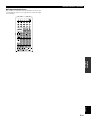
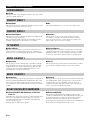
CONTROLS AND FUNCTIONS
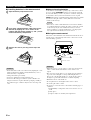
■ Opening and closing the front panel door
When you are not operating the controls behind the front panel
door, close the door.
N
A
T
U
R
A
L
S
O
U
N
D
A
V
A
M
P
L
IF
IE
R
D
S
P
–
A
Z
1

E-8
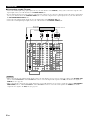
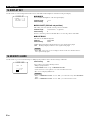
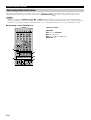
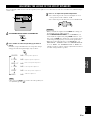
CONTROLS AND FUNCTIONS
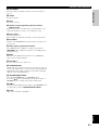
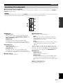
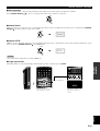
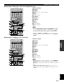
Remote control
1 Infrared window
Outputs infrared control signals. Aim this window at the component
you want to operate.
2 TRANSMIT
Flashes while the remote control is sending signals.
3 STANDBY
Sets this unit in the standby mode.
4 SYSTEM POWER
Turns on the power of this unit.
5 Display window
Shows the source component that you select to control.
6 SOURCE SELECT /
Selects the source component without switching the input.
7 LIGHT
Turns the light on or off.
When you press this button once, the light turns on for about 10
seconds. Press again to turn off the light.
8 Operation section
Provides functions such as play, stop, skip, etc. for operating your
other components.
Caution
• You can operate the other components that are not Yamaha with
this remote control after programming their remote control
functions (Learn) or setting the manufacturer code.
9 10KEY/DSP
Selects the numeric button (10KEY) mode or DSP mode. You can
use the 13 buttons to select numbers or DSP programs directly
according to the position of this switch.
0 EX/ES
Turns on or off the Dolby Digital EX or DTS ES decoder with
10KEY/DSP set to the DSP position.
q LEVEL
Selects the effect speaker channels (center, front, rear and
subwoofer) so you can adjust their level independently. Press this
button repeatedly to select the effect speaker channel you want to
adjust, then use + or – to adjust the level.
PUSH
TRANSMIT RE–NAME
CLEAR LEARN MACRO OFF ON
MACRO
SYSTEM
POWER
STANDBY
V–AUX TUNER PHONO
CABLE SAT MD/TAPE CD–R CD
D–TV/LD VCR 1 VCR 2 VCR3/DVR DVD
6CH INPUT
TITLE
DISPLAY
MENU
SOUND
ENTER
SOURCE
SEARCH
POWER
STOP PAUSE PLAYREC
CHAPTER
SELECT
10KEY DSP
1
HALL 1
2
HALL 2
3
CHURCH
4
5678
JAZZ CLUB
0
CHP/INDEX
+
10
+
100
ROCK
CONCERT
ENTER–
TAINMENT
CONCERT
VIDEO 1
CONCERT
VIDEO 2
9101112
TV
THEATER
EX/ES
MOVIE
THEATER 1
MOVIE
THEATER 2
/DTS
SUR.
TV VOL CH
VOLUME
DISC
PRESET
A/B/C/D/E
TV MUTE
TV INPUT
MUTE
EFFECT
STEREO
ON SCREEN
SLEEP
LEVEL
TEST
SET MENU
PARAMETER
1
t
y
u
i
o
p
a
s
d
f
2
3
4
5
6
7
9
0
q
w
e
r
8

E-9
INTRODUCTION
English
CONTROLS AND FUNCTIONS
w ON SCREEN
Selects the On-Screen Display mode for your video monitor (see
page 33).
e SLEEP
Sets the sleep timer.
r TEST
Selects the test mode.
t Remote control programming function buttons/
MACRO switch
Programs new remote control functions, sets manufacturer codes,
renames the input source names, or uses the Macro feature.
y Input section
Selects the input source.
Press an input selector button repeatedly to select the input mode.
u 6CH INPUT
Switches to the 6CH INPUT mode when using an external decoder
(see page 42).
i DSP program group/numeric buttons
Select DSP programs or numbers according to the position of
10KEY/DSP. (Press a button repeatedly to select a DSP program
within that group.)
o MUTE
Mutes the sound. While the mute function is on, “MUTE ON”
appears on the front panel display.
p VOLUME +/–
Increases or decreases the volume level.
a STEREO/EFFECT
Switches the effect speakers (center, front, rear, and rear center) on
and off. If the output of these speakers is switched off, all DTS and
Dolby Digital audio signals are directed to the main left and right
channels except for the LFE channel.
s PARAMETER/SET MENU
Selects the PARAMETER mode or SET MENU mode.
You can use / /+/– to adjust DSP program parameter values or
SET MENU items according to the position of this switch.
d / /+/–
Selects and adjusts DSP program parameters and SET MENU items
according to the position of PARAMETER/SET MENU.
f Cover
Slides down to show the setup buttons.

E-10
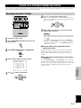
CONTROLS AND FUNCTIONS
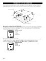
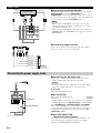
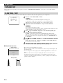
■ Installing batteries in the remote control
1
1
Open the battery compartment cover.
2
2
Insert three supplied batteries (LR6) in the correct
direction by aligning the + and – marks on the
batteries with the polarity markings (+ and –) on the
inside of the battery compartment.
3
3
Replace the cover as pressing until it snaps into
place.
Cautions
• Insert the batteries in the correct direction by aligning the + and –
marks on the batteries with the polarity illustrations (+ and –)
inside the battery compartment.
• Change the batteries periodically.
• Do not use old batteries together with new ones.
• Do not use different types of batteries (such as alkaline and
manganese batteries) together. Read the packaging carefully as
these different types of batteries may have the same shape and
color.
RESET
■ About changing batteries
As the batteries wear out, the operating range of the remote control
decreases and the TRANSMIT indicator does not flash or its light
becomes dim. When you notice any of these conditions, change all
of the batteries. After you insert new batteries, be sure to push
RESET in the battery compartment using a ball point pen or similar
object before using the remote control. (This does not clear the
contents of the memory.)
Caution
• If the remote control is without batteries for more than 3 minutes,
or if exhausted batteries remain in the remote control, the contents
of the memory may be cleared. When the memory is cleared,
insert new batteries, set up the manufacturer code and program
any acquired functions that may have been cleared.
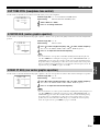
■ Using the remote control
The remote control transmits a directional infrared beam. Be sure to
aim the remote control directly at the remote control sensor on the
main unit during operation.
Cautions
• When the sensor is covered or there is a large object between the
remote control and the main unit, the sensor cannot receive
signals.
• The sensor may not be able to receive signals properly when it is
exposed to direct sunlight or a strong artificial light (such as a
fluorescent or strobe light). In this case, change the direction of
the light or reposition the main unit to avoid direct lighting.
• Handle the remote control with care.
• Do not spill water or other liquids on the remote control.
• Do not drop the remote control.
• Do not leave or store the remote control in the following types of
conditions:
1 high humidity or temperature such as near a heater, stove or
bath
2 dusty places
3 in places subject to extremely low temperatures
STANDBY
/ON
INPUT MODE
INPUT SELECTOR
VOLUME
NATURAL SOUND AV AMPLIFIER DSP–AZ1
30° 30°
Approximately 6 m (20 feet)
Remote control

E-11
INTRODUCTION
English
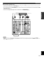
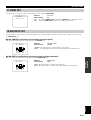
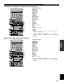
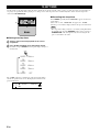
CONTROLS AND FUNCTIONS
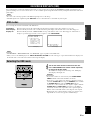
Front panel display
1 Input source indicator
Shows the current input source with the arrow-shaped cursor.
2 DSP indicator
Lights up when you select a digital sound field program.
3
96kHz
/
24bit
indicator
Lights up when the DTS 96/24 signal is input to this unit.
4 Processor indicators
When any function of DTS, MATRIX, DISCRETE, g,
and
PRO LOGIC
/
is activated, its indicator lights up.
5 Multi-information display
Shows the current DSP program and other information when
adjusting or changing settings.
6 VOLUME level indicator
Indicates the volume level.
7 SLEEP indicator
Lights up while the sleep timer is on.
D–TV/LD DVD
CABLE
MD/TAPE
SAT
CD–R
VCR 1 TUNER
VCR 2 CD
VCR3/DVR
PHONO
V–AUX
SLEEP
VIRTUAL
MATRIX
DISCRETE
DIGITAL
PRO LOGIC
/
96kHz
/
24bit
DSP
PCM
VOLUME
LFE
L C R
RL
SP
AB
SILENT
RC RR
1
789 0qwer
234 5 6
8 VIRTUAL indicator
Lights up when using Virtual CINEMA DSP (see page 49).
9 PCM indicator
Lights up when this unit is reproducing PCM (Pulse Code Modula-
tion) digital audio signals.
0 Headphones indicator
Lights up when headphones are connected.
q SPEAKERS A/B indicator
Lights up according to which set of main speakers are selected.
Both indicators light up when both sets of speakers are selected.
w SILENT indicator
Lights up when headphones are connected with the sound effect
(see “SILENT CINEMA DSP” on page 49).
e Input channel indicator
Indicates the channel components of input signals being received.
r LFE indicator
Lights up when the input signal contains the LFE signal.

E-12
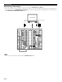
CONTROLS AND FUNCTIONS
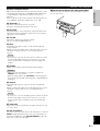
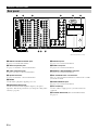
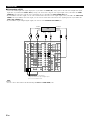
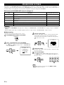
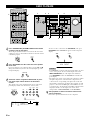
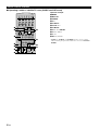
Rear panel
1 DIGITAL OPTICAL/COAXIAL jacks
See page 19 for detailed information.
2 Audio component jacks
See pages 19 and 20 for connection information.
3 Video component jacks
See pages 21 to 28 for connection information.
4 Speaker terminals
See pages 29 and 30 for connection information.
5 MAINS
Use this inlet to plug in the supplied power cord.
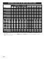
6 IMPEDANCE SELECTOR
Use this switch to match the amplifier output to your speaker
impedance. Turn off the power before you change the setting of this
switch (see page 30).
AC OUTLETS
IMPEDANCE SELECTOR
SET BEFORE POWER ON
MAINS
SWITCHED
SPEAKERS
R L
FRONT
R
R L
L
REAR
CENTER
MAIN
B
R L
A
REAR CENTER
(
SURROUND
)
CAUTION
SEE INSTRUCTION MANUAL FOR CORRECT SETTING.
A
DVD
COMPONENT VIDEO
AUDIOAUDIODIGITAL
ZONE 2 OUTDIGITAL
VIDEO
B
D–TV
/LD
C
SAT
MONITOR
OUT
FRONT
IN
FRONT
OUT
REAR
(
SURROUND
)
SUB
WOOFER
SPLIT
MONO
REAR CTR
IN
OUT
REMOTE 1
IN
CTRL
OUT
+12V
10mA
MAX.
RS–
232C
REMOTE 2
CENTER
IN
CENTER
OUT
YP
B
/C
B
P
R
/C
R
R L
PREOUT/MAIN IN
CONTROL
MAIN
IN
MAIN
OUT
R L
VIDEO
DVD
PHONO
GND
CD
S VIDEO
LRR L
CABLE
SAT
IN
VCR 1
OUT
IN
VCR 2
OUT
IN
VCR 3
/DVR
OUT
VIDEO
6CH INPUT
CENTER
SUB
WOOFER
VCR 3
/DVR
1
MONITOR
OUT
2
D–TV
/LD
L
SURROUND
MAIN
R
1
TUNER
CD–R
2
IN
(PLAY)
3
OUT
(REC)
4
MD/TAPE
IN
(PLAY)
3
OUT
(REC)
4
OPTICAL
IN
OPTICAL
OUT
COAXIAL
IN
w
D–TV
/LD
0
MD/
TAPE
6
SAT
q
DVD
9
CD–R
8
CD
7
CD–R
5
CABLE
4
DVD
3
CD
2
LD
LD
RF
(AC–3)
1
VOLTAGE SELECTOR
FRONT
REAR
REAR CENTER
CENTER
MAIN A OR B
A + B
:
6Ω
MIN. /SPEAKER
:
4Ω
MIN. /SPEAKER
:
4Ω
MIN. /SPEAKER
:
4Ω
MIN. /SPEAKER
:
4Ω
MIN. /SPEAKER
:
8Ω
MIN. /SPEAKER
FRONT
REAR
REAR CENTER
CENTER
MAIN A OR B
A + B
:
8Ω
MIN. /SPEAKER
:
8Ω
MIN. /SPEAKER
:
8Ω
MIN. /SPEAKER
:
8Ω
MIN. /SPEAKER
:
8Ω
MIN. /SPEAKER
:
16 Ω
MIN. /SPEAKER
12 3 4 5 6
78 0q w
e9
7 6CH INPUT jacks
See page 32 for connection information.
8 ZONE 2 OUT jacks
See page 83 for connection information.
9 REMOTE 1 IN/OUT/REMOTE 2 IN jacks
See page 83 for connection information.
0 RS-232C/CTRL OUT +12V terminals
These are control expansion terminals for commercial use. Consult
your dealer for details.
q PREOUT/MAIN IN jacks
See page 31 for connection information.
w AC OUTLET(S)
Use these outlets to supply power to your other audio/video
component.
e VOLTAGE SELECTOR (General and China models)
See page 32.
(General and China models)

PREPARATIONS
English
E-13
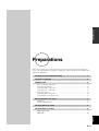
Preparations
Preparations
This section explains how to make preparations (speaker selection and placement, subwoofer
usage, connection with other components, speaker mode setting, and speaker level adjustment) to
fully use the DSP-AZ1.
SPEAKER SYSTEM CONFIGURATIONS .......................................................... 14
SPEAKER PLACEMENT .................................................................................... 16
CONNECTIONS .................................................................................................. 18
Before connecting components ................................................................................... 18
Connecting digital jacks .............................................................................................. 19
Connecting audio components .................................................................................... 19
Connecting video components .................................................................................... 21
Connecting speakers ................................................................................................... 29
Connecting other components .................................................................................... 31
Connecting the power supply cords ............................................................................ 32
ON-SCREEN DISPLAYS (OSD) ......................................................................... 33
OSD modes ................................................................................................................. 33
Selecting the OSD mode ............................................................................................. 33
SPEAKER MODE SETTINGS ............................................................................ 34
SPEAKER OUTPUT LEVELS ............................................................................ 38
TEST DOLBY SUR. .................................................................................................. 39
TEST DSP ................................................................................................................... 40

E-14
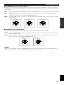
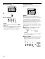
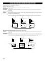
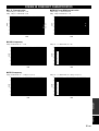
SPEAKER SYSTEM CONFIGURATIONS
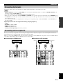
The most complete speaker configuration consists of eight speakers: the left and right main speakers, a center speaker, the left and right rear
speakers, the left and right front effect speakers, and a rear center speaker. If you do not use eight speakers, you can direct the signals for
speakers that are not in your system to other speakers in your configuration. A subwoofer can be used with any of these configurations to
produce a fuller sound.
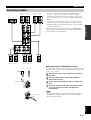
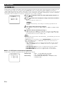
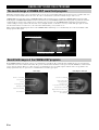
■ 8-speaker configuration –full CINEMA-DSP–
When you reproduce feature film software, this configuration fully expresses the powerful and realistic sound qualities of 70 mm multitrack
audio. The dialogue is positioned as if it were coming from directly on the screen, the sound effect is positioned slightly behind the screen,
and the soundtrack music is positioned even further behind the screen to express the width and depth of the overall presentation. This
configuration makes the most of this unit's capability.
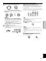
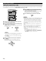
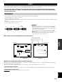
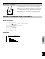
■ 6-speaker configuration –Hi-Fi DSP–
This configuration is used the most for audio playback with Hi-Fi DSP. It does not position the dialogue sound as well as a 7- or 8-speaker
configuration. However, it creates a dynamic DSP (Digital Sound Field Processor) sound field which adds depth to the sound.
For this speaker configuration, change SET MENU item “1A CENTER SP” to “NONE” and “1D REAR CT SP” to “NONE”.
Front effect speaker (FL)
TV (monitor)
Front effect speaker (FR)
Main speaker (R)
Rear effect speaker (RR)
1.5 – 1.8 m
(5 – 6 feet)
Center speaker (C)
Rear center speaker (RC)
Main speaker (L)
Rear effect speaker (RL)
Speakers to be used
• Main L/R
• Center
• Rear L/R
• Front effect L/R
• Rear center
RL
FR
RR
FL
L
C
R
RC
RL
FR
RR
FL
L
R
(L+C) (R+C)
Speakers to be used
• Main L/R
• Rear L/R
• Front effect L/R

E-15
PREPARATIONS
English
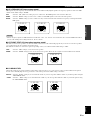
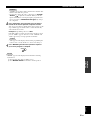
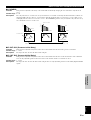
SPEAKER SYSTEM CONFIGURATIONS
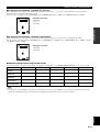
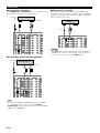
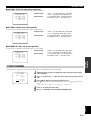
■ 5-speaker configuration –standard 5.1 channel–
This configuration does not express the height of the sound field as well as the 7- or 8-speaker configuration. However, it positions the
dialogue sound as coming directly from the screen.
For this speaker configuration, change SET MENU item “1F FRONT EFCT SP” to “NONE” and “1D REAR CT SP” to “NONE”.
■ 4-speaker configuration –minimum requirement–
In this configuration, the center speaker signals and front effect speaker signals are directed to the left and right main speakers.
For this speaker configuration, change SET MENU item “1A CENTER SP” to “NONE”, item “1F FRONT EFCT SP” to “NONE”, and item
“1D REAR CT SP” to “NONE”.
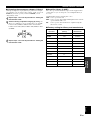
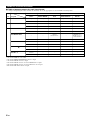
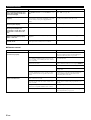
■ Speaker configurations and speaker mode
Select the appropriate speaker mode depending on the speaker configuration. See “SPEAKER MODE SETTINGS” on page 34 for details.
Speakers to be used
• Main L/R
• Center
• Rear L/R
RL
RR
L
R
C
(L+FL) (R+FR)
RL
RR
L
R
(L+C+FL) (R+C+FR)
Speakers to be used
• Main L/R
• Rear L/R
1A CENTER SP
(Center)
1B MAIN SP
(Main L/R)
1C REAR L/R SP
(Rear L/R)
1D REAR CT SP
(Rear center)
1F FRONT EFCT SP
(Front effect L/R)
Note
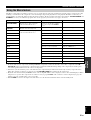
• As a guideline, select “LARGE” for the larger speaker diameter than 16 cm, and “SMALL” for the smaller speaker diameter than 15 cm.
Change the speaker mode setting as listening to the actual playback sound if it does not meet your expectation.
8 speakers
LRG/SML
LARGE/SMALL
LRG/SML
LRG/SML
YES
7 speakers
LRG/SML
LARGE/SMALL
LRG/SML
NONE
YES
6 speakers
NONE
LARGE/SMALL
LRG/SML
NONE
YES
5 speakers
LRG/SML
LARGE/SMALL
LRG/SML
NONE
NONE
4 speakers
NONE
LARGE/SMALL
LRG/SML
NONE
NONE

E-16
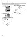
SPEAKER PLACEMENT
Refer to the following diagram when you place the speakers.
Caution
• Use magnetically shielded speakers. If this type of speakers still creates the interference with a monitor, place the speakers away from the
monitor.
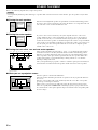
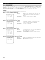
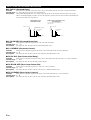
■ Placing the main speakers
Place the left and right main speakers an equal distance from the main listening position.
If you have a TV or video monitor in your system, the distance of each speaker from each
side of the TV or video monitor should be the same.
■ Placing the center speaker
If you have a TV or video monitor in your system, align the front face of the center
speaker with the front face of the monitor. Place the speaker as close to the monitor as
possible, such as directly over or under the monitor. If you place the speaker under the
monitor, the front effect speakers can adjust the height of the sound to correspond with the
action on the screen (depending on the listener’s position). If you have a projection screen
in your system, place the center speaker under the screen. Be sure to align the speaker
with the center of the screen.
Main
speaker
Main
speaker
TV or video
monitor
Center speaker
TV or video
monitor
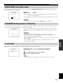
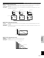
■ Placing the front effect, rear and rear center speakers
These speakers should be placed about 0.5 – 1 m (1 – 3 feet) outside the main speakers
and in the front of the room. They should be turned toward the main listening position.
Place the rear speakers in the back of the room so they face the main listening position.
The rear speakers can be placed farther apart than the front effect speakers. Place these
speakers at the height of 1.5 m when listening as sitting on the floor or 1.8 m when
listening as sitting on the chair.
Once you begin listening to programs, continue to adjust the speaker placement until you
obtain a balanced sound from the main speakers and the front effect and rear speakers.
This distance can be farther than the front
effect speakers’.
RL
FR
RR
FL
L
C
R
RC
1m 0.5 - 1m 1.5 - 3m 0.5 - 1m 1m
(3ft) (1 - 3ft) (5 - 15ft) (1 - 3ft) (3ft)
■ When you use a projection screen
Place the speakers as shown in the illustration.
The main speakers should be placed about one-quarter of the way up from the bottom of
the screen.
Place the center speaker in the center and directly under the screen. The center speaker
provides precise dialogue localization.
When you use a projection screen with your system, the front effect speakers provide
better effect quality. The CINEMA-DSP sound field programs (see pages 90 to 94) raise
the sound from the center speaker upward and provide natural sound corresponding with
the video images.
L
C
R
1/4
1
Screen

E-17
PREPARATIONS
English
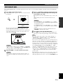
SPEAKER PLACEMENT
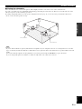
■ Placing the subwoofers
Place the front subwoofer near the main speakers. Turn it slightly toward the center of the room to reduce wall reflections.
If you use a rear subwoofer, place it behind the main listening position. The placement of the rear subwoofer is not critical because of the
ultra low frequencies of the sound being reproduced.
By adding a high quality subwoofer to the speaker configurations shown on page 14, you can enjoy more powerful and realistic movie
effects, even if your main speakers are large.
Note
• If you use different brands of speakers (with different tonal qualities) in your configuration, the tone of a moving human voice and other
types of sound may not shift smoothly. We recommend that you use speakers from the same manufacturer or speakers with the same tonal
quality.
You can also adjust the output levels and equalization of your effect speakers using the SET MENU (see pages 56 and 57).
If you are using small speakers, the addition of a subwoofer will reinforce the sound effects of movies.
Front subwoofer
Rear subwoofer

E-18
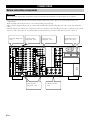
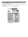
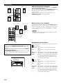
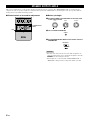
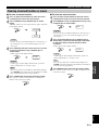
CONNECTIONS
Before connecting components
CAUTION
Never connect this unit and other components to mains power until all connections between components have been completed.
• Some components require different connection methods and have different jack names. Refer to the operation instructions for each
component also.
• Input and output jacks for the pin jacks are color-coded depending on the signal type.
• When connecting input and output jacks, use commercially available cables (pin-plug cable, fiber-optic cable, coaxial cable and S-Video
cable).
• When this unit interferes with the other components (such as a TV and tuner), replace this unit apart from those components. To prevent the
interference with a TV or tuner, it is recommended that an external antenna is placed and coaxial cables are used for connections.
AC OUTLETS
IMPEDANCE SELECTOR
SET BEFORE POWER ON
MAINS
SWITCHED
SPEAKERS
R L
FRONT
R
R L
L
REAR
CENTER
MAIN
B
R L
A
REAR CENTER
(
SURROUND
)
CAUTION
SEE INSTRUCTION MANUAL FOR CORRECT SETTING.
A
DVD
COMPONENT VIDEO
AUDIOAUDIODIGITAL
ZONE 2 OUTDIGITAL
VIDEO
B
D–TV
/LD
C
SAT
MONITOR
OUT
FRONT
IN
FRONT
OUT
REAR
(
SURROUND
)
SUB
WOOFER
SPLIT
MONO
REAR CTR
IN
OUT
REMOTE 1
IN
CTRL
OUT
+12V
10mA
MAX.
RS–
232C
REMOTE 2
CENTER
IN
CENTER
OUT
YPB/CB PR/CR
R L
PREOUT/MAIN IN
CONTROL
MAIN
IN
MAIN
OUT
R L
VIDEO
DVD
PHONO
GND
CD
S VIDEO
LRR L
CABLE
SAT
IN
VCR 1
OUT
IN
VCR 2
OUT
IN
VCR 3
/DVR
OUT
VIDEO
6CH INPUT
CENTER
SUB
WOOFER
VCR 3
/DVR
1
MONITOR
OUT
2
D–TV
/LD
L
SURROUND
MAIN
R
1
TUNER
CD–R
2
IN
(PLAY)
3
OUT
(REC)
4
MD/TAPE
IN
(PLAY)
3
OUT
(REC)
4
OPTICAL
IN
OPTICAL
OUT
COAXIAL
IN
w
D–TV
/LD
0
MD/
TAPE
6
SAT
q
DVD
9
CD–R
8
CD
7
CD–R
5
CABLE
4
DVD
3
CD
2
LD
LD
RF
(AC–3)
1
VOLTAGE SELECTOR
FRONT
REAR
REAR CENTER
CENTER
MAIN A OR B
A + B
:
6Ω
MIN. /SPEAKER
:
4Ω
MIN. /SPEAKER
:
4Ω
MIN. /SPEAKER
:
4Ω
MIN. /SPEAKER
:
4Ω
MIN. /SPEAKER
:
8Ω
MIN. /SPEAKER
FRONT
REAR
REAR CENTER
CENTER
MAIN A OR B
A + B
:
8Ω
MIN. /SPEAKER
:
8Ω
MIN. /SPEAKER
:
8Ω
MIN. /SPEAKER
:
8Ω
MIN. /SPEAKER
:
8Ω
MIN. /SPEAKER
:
16 Ω
MIN. /SPEAKER
Connecting digital jacks
^ P.19
Connecting audio
components ^ P.19
Connecting video
components ^ P.21
Connecting the power
supply cords ^ P.32
Connecting other
components ^ P.31
Connecting speakers
^ P.29
Sayfa yükleniyor...
Sayfa yükleniyor...
Sayfa yükleniyor...
Sayfa yükleniyor...
Sayfa yükleniyor...
Sayfa yükleniyor...
Sayfa yükleniyor...
Sayfa yükleniyor...
Sayfa yükleniyor...
Sayfa yükleniyor...
Sayfa yükleniyor...
Sayfa yükleniyor...
Sayfa yükleniyor...
Sayfa yükleniyor...
Sayfa yükleniyor...
Sayfa yükleniyor...
Sayfa yükleniyor...
Sayfa yükleniyor...
Sayfa yükleniyor...
Sayfa yükleniyor...
Sayfa yükleniyor...
Sayfa yükleniyor...
Sayfa yükleniyor...
Sayfa yükleniyor...
Sayfa yükleniyor...
Sayfa yükleniyor...
Sayfa yükleniyor...
Sayfa yükleniyor...
Sayfa yükleniyor...
Sayfa yükleniyor...
Sayfa yükleniyor...
Sayfa yükleniyor...
Sayfa yükleniyor...
Sayfa yükleniyor...
Sayfa yükleniyor...
Sayfa yükleniyor...
Sayfa yükleniyor...
Sayfa yükleniyor...
Sayfa yükleniyor...
Sayfa yükleniyor...
Sayfa yükleniyor...
Sayfa yükleniyor...
Sayfa yükleniyor...
Sayfa yükleniyor...
Sayfa yükleniyor...
Sayfa yükleniyor...
Sayfa yükleniyor...
Sayfa yükleniyor...
Sayfa yükleniyor...
Sayfa yükleniyor...
Sayfa yükleniyor...
Sayfa yükleniyor...
Sayfa yükleniyor...
Sayfa yükleniyor...
Sayfa yükleniyor...
Sayfa yükleniyor...
Sayfa yükleniyor...
Sayfa yükleniyor...
Sayfa yükleniyor...
Sayfa yükleniyor...
Sayfa yükleniyor...
Sayfa yükleniyor...
Sayfa yükleniyor...
Sayfa yükleniyor...
Sayfa yükleniyor...
Sayfa yükleniyor...
Sayfa yükleniyor...
Sayfa yükleniyor...
Sayfa yükleniyor...
Sayfa yükleniyor...
Sayfa yükleniyor...
Sayfa yükleniyor...
Sayfa yükleniyor...
Sayfa yükleniyor...
Sayfa yükleniyor...
Sayfa yükleniyor...
Sayfa yükleniyor...
Sayfa yükleniyor...
Sayfa yükleniyor...
Sayfa yükleniyor...
Sayfa yükleniyor...
Sayfa yükleniyor...
Sayfa yükleniyor...
Sayfa yükleniyor...
Sayfa yükleniyor...
Sayfa yükleniyor...
Sayfa yükleniyor...
Sayfa yükleniyor...
Sayfa yükleniyor...
Sayfa yükleniyor...
-
 1
1
-
 2
2
-
 3
3
-
 4
4
-
 5
5
-
 6
6
-
 7
7
-
 8
8
-
 9
9
-
 10
10
-
 11
11
-
 12
12
-
 13
13
-
 14
14
-
 15
15
-
 16
16
-
 17
17
-
 18
18
-
 19
19
-
 20
20
-
 21
21
-
 22
22
-
 23
23
-
 24
24
-
 25
25
-
 26
26
-
 27
27
-
 28
28
-
 29
29
-
 30
30
-
 31
31
-
 32
32
-
 33
33
-
 34
34
-
 35
35
-
 36
36
-
 37
37
-
 38
38
-
 39
39
-
 40
40
-
 41
41
-
 42
42
-
 43
43
-
 44
44
-
 45
45
-
 46
46
-
 47
47
-
 48
48
-
 49
49
-
 50
50
-
 51
51
-
 52
52
-
 53
53
-
 54
54
-
 55
55
-
 56
56
-
 57
57
-
 58
58
-
 59
59
-
 60
60
-
 61
61
-
 62
62
-
 63
63
-
 64
64
-
 65
65
-
 66
66
-
 67
67
-
 68
68
-
 69
69
-
 70
70
-
 71
71
-
 72
72
-
 73
73
-
 74
74
-
 75
75
-
 76
76
-
 77
77
-
 78
78
-
 79
79
-
 80
80
-
 81
81
-
 82
82
-
 83
83
-
 84
84
-
 85
85
-
 86
86
-
 87
87
-
 88
88
-
 89
89
-
 90
90
-
 91
91
-
 92
92
-
 93
93
-
 94
94
-
 95
95
-
 96
96
-
 97
97
-
 98
98
-
 99
99
-
 100
100
-
 101
101
-
 102
102
-
 103
103
-
 104
104
-
 105
105
-
 106
106
-
 107
107
-
 108
108
-
 109
109
-
 110
110


diğer dillerde
- français: Yamaha DSP-AZ1 Le manuel du propriétaire
- italiano: Yamaha DSP-AZ1 Manuale del proprietario
- svenska: Yamaha DSP-AZ1 Bruksanvisning
- Deutsch: Yamaha DSP-AZ1 Bedienungsanleitung
- English: Yamaha DSP-AZ1 Owner's manual
- dansk: Yamaha DSP-AZ1 Brugervejledning
- Nederlands: Yamaha DSP-AZ1 de handleiding
- română: Yamaha DSP-AZ1 Manualul proprietarului
İlgili makaleler
-
Yamaha DSP-AX2 El kitabı
-
-
Yamaha DSP-E580 El kitabı
-
Yamaha DSP-100 El kitabı
-
-
-
-
Yamaha DSP-AZ2 Kullanım kılavuzu
-
-