
i En
English Français Deutsch Svenska Italiano Español Nederlands Русский
1 The installation of this unit demands carefully performed work, so take
care in terms of safety during the installation. Read this install manual
carefully prior to starting the assembly and installation work. Yamaha
shall not bear any responsibility for any accidents or injury that occur due
to careless assembly, installation or use of this product.
2 Install this unit on a flat and stable place that can support sufficient
weight. If you install this unit in an unstable place, such as on a carpet or
a straw mat, place a board under the unit. If installed in a poor location,
your TV/speaker may tip over or fall off the stand, resulting in personal
injury.
3 When you install this unit, take measures to prevent it from falling over
by attaching wire or the L bracket.
4 Do not install the unit against a sliding door, a partition or other place that
is not sturdy enough.
5 Be sure that the installation is performed by two or more people. When
moving the unit, lift it up from the base board and carry. If you lift it up
by other than the base board, it may damage this unit.
6 Be sure to use all of the screws and/or mounting hardware indicated in the
install manual. Tighten screws securely in every location as directed.
7 Do not lean on or place objects on the corner of your TV/speaker.
8 Do not rattle or hit the unit.
9 Do not make any alterations to parts or use any broken parts.
10 Do not install in a humid or dusty place, or where your TV/speaker would
be subject to steam or oily smoke.
11 Install this unit in a well-ventilated, cool, dry and clean place. For
minimum clearances for proper ventilation, refer to the owner’s manual
of your TV/speaker.
12 Mount your TV/speaker properly. If not, your TV/speaker may tip over or
fall off the stand, resulting in personal injury.
13 Do not use on a wet or waxed floor. If this product is used in such a
location, it may stick to the floor.
14 Install in a place that does not get too hot. Installing it under direct
sunlight or close to a heater may result in bubbling, peeling or
discoloration of painted surfaces.
15 Do not apply cellophane tape or other adhesive materials to painted
surfaces, as the paint may peel.
16 Use a dry cloth to remove dust or dirt. If the unit is very dirty, wet the
cloth in a neutral detergent diluted with water and wring it out well before
wiping the unit. Note that if products like benzene, paint thinner or
household wax are used, they may cause the paint to fade and/or damage
the finish.
17 Do not drop a sharp object on this unit, as damage may result.
18 This install manual provides explanations of important precautions to
take to avoid any accidents, as well as how to assemble and install the
unit. During installation, also refer to the owner's manuals of your TV and
speaker, and attain a good understanding of them before proceeding
according to their directions.
19 After reading, keep this manual in a safe place for future reference.
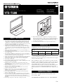
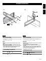
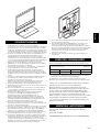
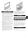
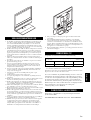
Compatible TV size: up to 52-inch, under 45 kg
* Compliant with VESA Mounting Interface Standard and with the distance
between mounting holes described above.
The diameter of the screws should be up to 8 mm (the diameter of the supplied
screws are 5 mm, 6 mm, 8 mm).
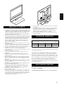
Before installation, read the owner’s manual of your TV or measure
the distance of the mounting holes on the rear panel of your TV, and
check if your TV is possible to install. Note that even if the distance
of the mounting holes of your TV is the same as the distance
described above, there may be a case that you cannot install your TV
if there is a projection or input/output terminal in the way of the
bracket attachment area or if the bracket blocks the ventilation of the
TV.
This product is compatible with the following speaker models.
(As of October, 2009)
YSP-4000/3000, YSP-5100/4100, YAS-81/71, YHT-S1400/S400
SAFETY PRECAUTION
COMPATIBLE TV
Compatible distance between mounting holes on the rear panel of the TV
(W × H)* unit = cm
20 × 20 30 × 20 30 × 30 40 × 20
40 × 30 40 × 40 50 × 20 60 × 40
COMPATIBLE SPEAKER
G
Integrated TV/Soundbar Pedestal
Socle intégré pour téléviseur et projecteur de son
YTS-T500
Install Manual
Manuel d’installation
Installationsanleitung
Installationsanvisningar
Printed in Malaysia WU17410
Manuale d’installazione
Manual de instalación
Installatiehandleiding
Руководство по установке

ii En
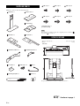
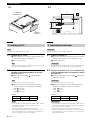
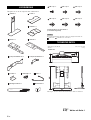
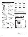
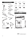
Make sure you have all of the following items.
In the following assembly procedure, these supplied parts are described as
for parts and for screws, etc.
• Dimensions (W × H × D) ...................................................... 650 × 867 × 398 mm
• Weight .........................................................................................................17.0 kg
Design and specifications are subject to change without notice.
SUPPLIED PARTS
: Pedestal × 1 : Base board × 1
: TV bracket × 1
: Bracket L × 1 : Bracket R × 1
: Speaker bracket A × 1 : Speaker bracket B × 1
: L bracket × 1 : Cable clips × 4 : Wire × 1
: Mounting template × 1 : Spacer × 1
Note
SPECIFICATIONS
(M5 × 16) × 7 (M5 × 16) × 7 (M5 × 20) × 8
(M6 × 16) × 8 (M6 × 20) × 4 (M8 × 20) × 4
Spare: Each size × 1
(6 screws in total)
Unit: mm
Continue to page 1
☞

i Fr
Français
1 L’installation de cette unité demande de la dextérité et de la précision. Par
conséquent, observez les consignes de sécurité lors de l’installation. Lisez
attentivement ce manuel d’installation avant de procéder aux travaux de
montage et d’installation. Yamaha décline toute responsabilité en cas
d’accident ou de blessure résultant d’un montage, d’une installation ou
d’une utilisation inadéquate de ce produit.
2 Choisissez sur une surface plane et stable capable de supporter le poids de
l’unité. Si vous installez cette unité sur une surface instable, notamment
sur un tapis ou une natte, posez au préalable une planche dessous. En cas
d’installation dans un endroit inadéquat, votre téléviseur/haut-parleur
risque de basculer hors du support et vous risquez de vous blesser.
3 Lors de l’installation, prenez les mesures nécessaires pour éviter que
l’unité ne tombe, notamment en utilisant l’attache métallique ou le
support en forme de L fournis.
4 N’installez pas l’unité contre une porte coulissante, une cloison ou tout
autre support instable.
5 Veillez à ce que l’installation soit effectuée par au moins deux personnes.
Lorsque vous déplacez l’unité, soulevez-la en la saisissant par la base.
Vous risquez d’endommager l’unité si vous ne la saisissez pas par la base.
6 Utilisez les vis et le matériel de fixation indiqués dans le manuel
d’installation. Serrez les vis correctement, comme indiqué.
7 Veillez à ne rien appuyer contre votre téléviseur/haut-parleur et à ne poser
aucun objet dessus.
8 L’unité ne doit subir aucun choc violent.
9 Vous ne devez modifier aucun composant et n’utiliser aucune pièce
endommagée.
10 N’installez pas le téléviseur/haut-parleur dans un endroit exposé à
l’humidité ou à la poussière, ni dans un endroit qui dégage de la vapeur
d’eau ou d’essence.
11 Installez l’unité dans un endroit frais, sec, propre et correctement aéré.
Pour en savoir davantage sur les espaces libres minimums nécessaires à
une bonne ventilation, reportez-vous au mode d’emploi du téléviseur/
haut-parleur.
12 Montez votre téléviseur/haut-parleur correctement. Dans le cas contraire,
votre téléviseur/haut-parleur risque de basculer hors du support et vous
risquez de vous blesser.
13 N’installez pas votre téléviseur/haut-parleur sur un sol humide ou ciré. Le
cas échéant, il risque d’adhérer au sol.
14 Installez le téléviseur/haut-parleur dans un endroit tempéré. Si vous
l’installez dans un endroit exposé à la lumière directe du soleil ou à
proximité d’une source de chaleur, les surfaces peintes risquent de se
gondoler, de s’écailler ou de se décolorer.
15 N’appliquez pas de ruban adhésif sur les surfaces peintes, car vous
risquez d’écailler la peinture.
16 Nettoyez la poussière ou la saleté avec un chiffon sec. Si l’unité est très
sale, imprégnez un chiffon d’une solution détergente neutre diluée dans
de l’eau en prenant soin de bien essorer le chiffon avant de procéder au
nettoyage. Notez que certains produits tels que l’essence, le diluant ou la
cire doivent être proscrits, car ils risquent de décolorer et/ou
d’endommager les surfaces peintes.
17 Veillez à n’utiliser aucun objet pointu sur cette unité, car vous risquez de
l’endommager.
18 Ce manuel d’installation contient des consignes de sécurité importantes
afin d’éviter tout accident, ainsi que des explications sur le montage et
l’installation de l’unité. Avant de procéder à l’installation, lisez
attentivement la documentation fournie avec le téléviseur et le haut-
parleur et suivez les instructions qui vous sont données.
19 Une fois l’installation terminée, conservez ce manuel en lieu sûr pour
toute référence future.
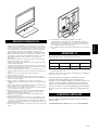
Formats compatibles : jusqu’à 52 pouces, moins de à 45 kg
* Conforme à la norme VESA MIS (VESA Mounting Interface Standard) et
à la distance entre les trous de montage décrits ci-dessus.
Le diamètre des vis doit être de 8 mm maximum (le diamètre des vis fournies
est de 5 mm, 6 mm et 8 mm).
Avant de procéder à l’installation, consultez le mode d’emploi de
votre téléviseur ou mesurez la distance entre les trous de montage
situés sur le panneau arrière afin de vérifier si l’installation de votre
téléviseur est possible. Notez toutefois que même si la distance entre
les trous de montage de votre téléviseur correspond à celle décrite ci-
dessus, il est possible que vous ne puissiez pas installer votre
téléviseur si une partie saillante ou une borne d’entrée/de sortie se
trouve dans la zone de fixation du support, ou si le support empêche
la ventilation du téléviseur.
Ce produit est compatible avec les modèles de haut-parleur suivants.
(À compter d’octobre 2009)
YSP-4000/3000, YSP-5100/4100, YAS-81/71, YHT-S1400/S400
CONSIGNES DE SÉCURITÉ
TÉLÉVISEURS COMPATIBLES
Distance compatible entre les trous de montage situés sur le panneau arrière
du téléviseur (L × H)* unité = cm
20 × 20 30 × 20 30 × 30 40 × 20
40 × 30 40 × 40 50 × 20 60 × 40
HAUT-PARLEUR COMPATIBLE

ii Fr
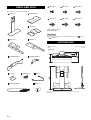
Vérifiez que les éléments suivants sont fournis.
Dans la procédure de montage ci-dessous, ces éléments fournis sont décrits de
la façon suivante : pour les pièces, pour les vis, etc.
• Dimensions (L × H × P) ........................................................ 650 × 867 × 398 mm
• Poids ............................................................................................................ 17,0 kg
La conception et les spécifications peuvent être modifiées sans avis préalable.
ÉLÉMENTS FOURNIS
: Socle × 1 : Base × 1
: Support de fixation du
téléviseur × 1
: Support L × 1 : Support R × 1
: Support de fixation du
haut-parleur A × 1
: Support de fixation du
haut-parleur B × 1
: Support en
forme de L × 1
: Collier de
câbles × 4
: Attache
métallique × 1
: Gabarit de montage × 1 : Entretoise × 1
Remarque
SPÉCIFICATIONS
(M5 × 16) × 7 (M5 × 16) × 7 (M5 × 20) × 8
(M6 × 16) × 8 (M6 × 20) × 4 (M8 × 20) × 4
Vis de réserve : chaque dimension × 1
(6 vis en tout)
Unité : mm

1 En/Fr
English Français
ASSEMBLING/MONTAGE
1-1 1-2
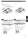
• y indicates a tip for your operation.
• In the MEMO box, note down dimensions and the number (on the mounting
template) measured during assembly.
• Make sure to perform this installation with 2 or more
people.
• Make sure to have a Phillips screwdriver that fits the
screws before assembling.
• In the case you secure parts or the TV with more than 4
screws, tighten all screws temporarily halfway, then
secure them in order of opposing corner.
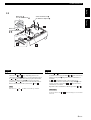
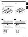
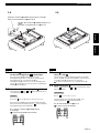
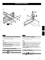
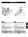
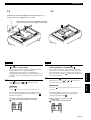
1-1 Attach to with (7 screws).
1-2 Attach with (3 screws).
English
Before Assembling
Notes
1 Assembling the pedestal
•Le symbole y appelle votre attention sur un conseil d’utilisation.
• Lors du montage, notez les dimensions mesurées et le numéro (qui figure
sur le gabarit de montage) dans le cadre MÉMO.
• Veillez à ce que l’installation soit effectuée par au moins
deux personnes.
• Vous devez disposer d’un tournevis Phillips
correspondant aux vis spécifiées avant de procéder au
montage.
• Si vous utilisez plus de 4 vis pour fixer le téléviseur ou
d’autres éléments, serrez provisoirement toutes les vis,
puis serrez-les à fond en diagonale.
1-1 Fixez à avec (7 vis).
1-2 Fixez avec (3 vis).
Français
Avant le montage
Remarques
1 Montage du socle

ASSEMBLING/MONTAGE
2 En/Fr
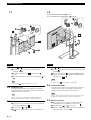
Blanket, etc.
Couverture, etc.
TV stand
Support TV
2-1 2-2
X
Y
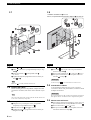
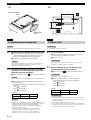
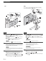
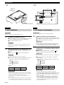
Also refer to the owner’s manual of your TV.
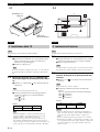
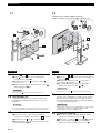
2-1 Remove the TV stand.
1 Place a blanket, etc. on a flat area, and place the TV on it
so that the screen does not get damaged.
2 Remove the TV stand.
Stand removal method may vary, depending on the TV. For details,
refer to the owner’s manual of your TV.
2-2 Measure the distance (X and Y) and the
diameter of the mounting holes on the rear
panel of your TV.
1 Measure the X and Y using or other measuring
instrument.
If screws are on the screw holes, remove them.
2 Check the diameter of the mounting hole of the TV.
Use the following screws depending on the diameter:
5 mm: (4 screws)
6 mm: (4 screws)
8 mm: (4 screws)
MEMO
• Before installing, check the depth of the mounting hole of the TV.
If the supplied screws do not fit, use washers or screws
commercially available.
• Prepare screws that can be tightened at least 5 turns.
• Be careful of the length of the screws if the round of the screw
holes sag downwards. Also, do not tighten screws too much as it
may cause distortion of the TV or other damage.
English
2 Installing the TV
Note
Note
Note
XYScrew
cm cm
Notes
Consultez également le mode d’emploi du téléviseur.
2-1 Retirez le support TV.
1 Placez une couverture sur une surface plane, puis posez le
téléviseur dessus afin de ne pas endommager l’écran.
2 Retirez le support TV.
La méthode de retrait du support peut varier en fonction du téléviseur.
Pour plus de détails, consultez le mode d’emploi du téléviseur.
2-2 Mesurez la distance (X et Y) et le diamètre des
trous de montage situés sur le panneau arrière
du téléviseur.
1 Mesurez les distances X et Y à l’aide de ou d’un autre
instrument de mesure.
Si les vis se trouvent dans les trous, retirez-les.
2 Mesurez le diamètre du trou de montage du téléviseur.
En fonction du diamètre, utilisez les vis suivantes :
5mm: (4vis)
6mm: (4vis)
8mm: (4vis)
MÉMO
• Avant l’installation, vérifiez la profondeur du trou de montage du
téléviseur. Si les vis fournies ne rentrent pas, utilisez des rondelles
et des vis vendues dans le commerce.
• Préparez des vis pouvant être serrées d’au moins 5 tours.
• Veillez à ne pas utiliser de vis trop longues, car celles-ci risquent de
se plier. Par ailleurs, ne serrez pas trop les vis, car vous risqueriez
de déformer le téléviseur.
Français
2 Installation du téléviseur
Remarque
Remarque
Remarque
XYVis
cm cm
Remarques

ASSEMBLING/MONTAGE
3 En/Fr
English Français
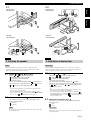
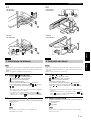
When using
Lors de l’utilisation de
When using /
Lors de l’utilisation de
/
2-3
Screws checked in 2-2-2
Vis définies à l’étape 2-2-2
*
2
*
1
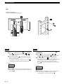
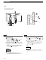
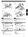
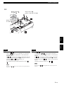
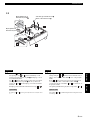
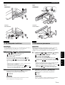
2-3 Attach and .
The holes for and vary depending on the screw
checked in step 2-2-2. Refer to *1 in the illustration above.
If and touch each other when you place them on the
TV (if X checked in step 2-2-1 is 20 cm), reverse the
position of and . Refer to *2 in the illustration above.
Refer to the illustration above, and secure and .
The arrows on and should be toward the top of the TV.
English
Note
2-3 Fixez et .
Le nombre de trous que possèdent et varie selon les vis
définies à l’étape 2-2-2. Reportez-vous à l’illustration *1
ci-dessus.
Si et se touchent lorsque vous les placez sur le
téléviseur, (si la distance X mesurée à l’étape 2-2-1 est de
20 cm), inversez la position de et . Reportez-vous à
l’illustration *2 ci-dessus.
Reportez-vous à l’illustration ci-dessus, puis fixez et .
Les flèches situées sur et doivent être dirigées vers le haut du
téléviseur.
Français
Remarque

ASSEMBLING/MONTAGE
4 En/Fr
2-4
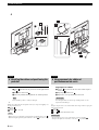
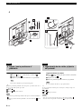
i.e. When using YSP-4100
Par ex., lors de l’utilisation de YSP-4100
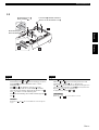
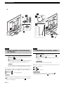
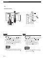
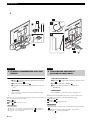
2-4 Check the location to attach and the TV.
1 Place over mounting hole A on or so that the
hole on aligns with mounting hole A on or
, as
shown in the illustration.
2 Check which number on is at the bottom of your TV.
Refer to the number shown on the bar that corresponds to
the name of your speaker.
If no number pertaining to your speaker exists, align
with mounting hole B, and check the number again.
MEMO
3 Tighten (2 screws) temporarily around 5 turns into the
holes at the same height as the corresponding number you
checked in 2.
English
Number
2-4 Vérifiez l’emplacement de montage de sur
le téléviseur.
1 Placez sur le trou de montage A de ou de
manière à aligner le trou situé sur au trou de montage
A de ou
, comme indiqué dans l’illustration.
2 Vérifiez quel numéro de est inscrit sur la partie
inférieure du téléviseur. Reportez-vous au numéro indiqué
sur la barre qui correspond au nom du haut-parleur.
Si aucun numéro n’est assigné à votre haut-parleur,
alignez au trou de montage B, puis vérifiez à nouveau
le numéro.
MÉMO
3 Serrez provisoirement (2 vis) d’environ 5 tours dans
les trous situés à la même hauteur que le numéro
correspondant que vous avez noté à l’étape 2.
Français
Numéro

ASSEMBLING/MONTAGE
5 En/Fr
English Français
Only when the X checked in 2-2-1 is 60 cm
Uniquement lorsque la distance X mesurée à l’étape
2-2-1 est de 60 cm
When the X checked in 2-2-1 is other than 60 cm
Lorsque la distance X mesurée à l’étape 2-2-1 n’est pas de 60 cm
2-5 2-6
2-5 Tighten (2 screws) temporarily in advance
to attach TV to .
If you checked which mounting holes to use with A in step
2-4, use mounting hole A, or in the case of B, use B. Refer to
the illustration above, and tighten (2 screws) temporarily
around 5 turns into either A or B.
2-6 Prepare to attach .
Place temporarily over and , and check which hole
to use.
The arrow on should be toward the top of the TV.
If you use mounting hole B in step 2-5, the mounting holes to
attach are shown below.
English
Note
i.e. When X checked in 2-2-1 is 40 cm
: position to tighten the screws
2-5 Serrez provisoirement (2 vis) pour fixer le
téléviseur à .
Si vous avez noté les trous de montage à utiliser avec A à
l’étape 2-4, utilisez le trou de montage A, ou B dans le cas de
B. Reportez-vous à l’illustration ci-dessous, puis vissez
provisoirement (2 vis) d’environ 5 tours dans A ou B.
2-6 Préparez pour le fixer.
Placez sur et , et vérifiez le trou à utiliser.
Les flèches situées sur doivent être dirigées vers le haut du
téléviseur.
Si vous utilisez le trou de montage B à l’étape 2-5, les trous
de montage permettant de fixer sont indiqués ci-dessous.
Français
Remarque
Par ex., lorsque la distance X mesurée à l’étape 2-2-1
est de 40 cm
: position pour serrer les vis

ASSEMBLING/MONTAGE
6 En/Fr
2-7 2-9
i.e. When X checked in 2-2-1 is 40 cm
Par ex., lorsque la distance X mesurée à l’étape 2-2-1 est de 40 cm
2-7 Attach to .
1 Hang on the screws you tightened temporarily in step
2-4-3.
2 Secure the bottom of to the pedestal with
(2 screws).
3 Tighten the temporarily tightened screws on which you
hung in 1.
Make sure is securely attached with 4 screws.
2-8 Connect the cables.
Before mounting the TV to the pedestal, complete the cable
connections. For details, refer to the owner’s manual of your
TV.
Also connect the cable for the speaker to the TV. For the details, refer
to the owner’s manual of your speaker.
2-9 Mount your TV.
1 Hang the TV by inserting the screws you tightened
temporarily in step 2-5 to the holes of .
2 Secure the TV and with (2 screws).
3 Tighten the temporarily tightened screws on which you
hung the TV in 1.
English
Note
Note
2-7 Fixez à .
1 Accrochez aux vis que vous avez provisoirement
serrées à l’étape 2-4-3.
2 Fixez la partie inférieure de au socle avec (2 vis).
3 Serrez provisoirement les vis sur lesquelles vous avez
accroché à l’étape 1.
Assurez-vous que est correctement fixé à l’aide des 4 vis.
2-8 Raccordez les câbles.
Avant d’installer le téléviseur sur le socle, vous devez
raccorder les câbles. Pour plus de détails, consultez le mode
d’emploi du téléviseur.
Raccordez également le câble qui relie le haut-parleur au téléviseur.
Pour plus de détails, consultez le mode d’emploi du haut-parleur.
2-9 Montez votre téléviseur.
1 Accrochez le téléviseur en insérant les vis que vous avez
provisoirement serrées à l’étape 2-5 dans les trous de .
2 Fixez le téléviseur et avec (2 vis).
3 Serrez provisoirement les vis sur lesquelles vous avez
accroché le téléviseur à l’étape 1.
Français
Remarque
Remarque

ASSEMBLING/MONTAGE
7 En/Fr
English Français
YAS-81/71
YSP-4000/3000
YSP-5100/4100
3-1
YAS-81/71
YHT-S1400/S400
YHT-S1400/S400
3-2
YSP-4000/3000
YSP-5100/4100
YAS-81/71
YHT-S1400/S400
• Before mounting the speaker to the pedestal, complete the cable
connections. For details, refer to the owner’s manual of your speaker.
• Remove the speaker stand when it is attached.
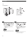
3-1 Attach or with (4 screws).
Choose or depending on the speaker.
: YSP-4000/3000, YSP-5100/4100
: YAS-81/71, YHT-S1400/S400
(As of October, 2009)
In the case of YHT-S1400/S400, attach to the terminal
side of the speaker. Align the holes on and , and stick
to as shown in the illustration above.
y
• You can adjust the height to set the speaker by using the holes
either at the top or at the bottom.
• You can adjust the height of the speaker by setting upside
down, only if you use and your speaker is YHT-S1400/S400. In
this case, attach to the terminal side of the speaker.
3-2 Mount the speaker with .
The number of screws you use varies depending on the
speaker bracket attached.
: 4 screws
: 2 screws
Be careful not to pinch the speaker cables between the speaker and
the speaker bracket.
English
3 Installing the speaker
Notes
Note
• Avant d’installer le haut-parleur sur le socle, vous devez raccorder les
câbles. Pour plus de détails, consultez le mode d’emploi du haut-parleur.
• Retirez le support du haut-parleur si celui-ci est fixé.
3-1 Fixez ou avec (4 vis).
Choisissez ou en fonction du haut-parleur.
: YSP-4000/3000, YSP-5100/4100
: YAS-81/71, YHT-S1400/S400
(À compter d’octobre 2009)
Pour les modèles YHT-S1400/S400, fixez au haut-
parleur, du côté où se trouvent les bornes. Alignez les trous
de et , puis assemblez et comme indiqué dans
l’illustration ci-dessus.
y
• Vous pouvez régler la hauteur du haut-parleur à l’aide des trous
situés dans la partie supérieure ou inférieure.
• Vous pouvez régler la hauteur du haut-parleur en installant à
l’envers, uniquement si vous utilisez et si votre haut-parleur est
YHT-S1400/S400. Dans ce cas, fixez au haut-parleur, du côté
où se trouvent les bornes.
3-2 Montez le haut-parleur avec .
Le nombre de vis que vous utilisez dépend du support de
haut-parleur fixé.
: 4 vis
: 2 vis
Prenez garde de ne pas coincer les câbles entre le haut-parleur et le
support de fixation.
Français
3 Installation du haut-parleur
Remarques
Remarque

ASSEMBLING/MONTAGE
8 En/Fr
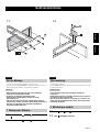
4
Bundle the cables.
1 Insert into the holes of your choice on the right and left
of .
2 Bundle the cables with .
3 Move the pedestal holding both the TV and the pedestal.
Do not hold the speaker, as it may be damaged.
y
When you position the pedestal against a wall, you can prevent toppling over
by the procedure below.
Attach .
Remove .
Secure to a solid wall.
• When you do not position the pedestal against a wall, make sure to use .
• When moving the pedestal again, make sure to attach , then move it.
English
4 Bundling the cables and positioning the
pedestal
Note
Notes
Regroupez les câbles.
1 Insérez dans les trous de votre choix situés de part et
d’autre de .
2 Regroupez les câbles avec .
3 Déplacez le socle qui maintient le téléviseur.
Lors du déplacement, ne saisissez pas le haut-parleur, car vous
risquez de l’endommager.
y
Lorsque vous placez le socle contre un mur, suivez la procédure ci-après pour
éviter qu’il ne bascule.
Fixez .
Retirez .
Fixez à un mur suffisamment solide.
• Si vous ne placez pas le socle contre un mur, vous devez utiliser .
• Lorsque vous déplacez à nouveau le socle, fixez au préalable.
Français
4 Regroupement des câbles et
positionnement du socle
Remarque
Remarques

i De
Deutsch
1 Die Installation dieses Ständers erfordert eine sorgfältige
Vorgehensweise. Beachten Sie während der Installation alle aufgeführten
Sicherheitshinweise. Lesen Sie diese Installationsanleitung vor Beginn
der Montage- und Installationsarbeiten sorgfältig durch. Yamaha ist nicht
verantwortlich für jegliche Sach- oder Personenschäden aufgrund einer
unsachgemäßen Montage, Installation oder Verwendung dieses Produkts.
2 Stellen Sie diesen Ständer an einem ebenen und stabilen Ort mit einer
ausreichenden Belastbarkeit auf. Wenn Sie den Ständer an einem
instabilen Ort wie etwa auf einem Teppich oder einer Strohmatte
aufstellen, legen Sie eine feste Platte unter den Ständer. Bei Aufstellung
an einem ungeeigneten Ort kann Ihr Fernsehgerät/Lautsprecher umkippen
oder vom Ständer herunterfallen und Verletzungen verursachen.
3 Ergreifen Sie bei der Installation dieses Ständers entsprechende
Maßnahmen wie etwa die Anbringung eines Drahts oder des L-Halters,
um ein Umkippen des Ständers zu verhindern.
4 Installieren Sie das Gerät nicht vor einer Schiebetür, einem Raumteiler
oder an einem anderen, nicht ausreichend robusten Ort.
5 Die Installationsarbeiten müssen unbedingt von mindestens zwei
Personen durchgeführt werden. Fassen Sie die Einheit (Ständer und
installierte Geräte) zu Transportzwecken unten am Sockel an. Wenn Sie
die Einheit nicht unten am Sockel anfassen, kann die Einheit beschädigt
werden.
6 Verwenden Sie unbedingt alle in der Installationsanleitung aufgeführte
Schrauben und/oder sämtliches Montagezubehör. Ziehen Sie die
Schrauben an jeder Stelle wie angegeben fest.
7 Lehnen Sie keine Gegenstände an die Kante Ihres Fernsehgeräts/
Lautsprechers und legen Sie auch keine Gegenstände darauf ab.
8 Setzen Sie die Einheit keinen Stößen und Erschütterungen aus.
9 Nehmen Sie keine Veränderungen an den Teilen vor und verwenden Sie
keine beschädigten Teile.
10 Stellen Sie die Einheit nicht an einem feuchten oder staubigen Ort auf
oder an einem Ort, an dem Ihr Fernsehgerät/Lautsprecher Dampf oder
ölhaltigem Dunst ausgesetzt ist, auf.
11 Stellen Sie dieses Klangsystem an einem gut belüfteten, kühlen,
trockenen und sauberen Ort auf. Die Mindestabstände zur
Gewährleistung einer ausreichenden Belüftung sind in der
Gebrauchsanleitung Ihres Fernsehgeräts/Lautsprechers aufgeführt.
12 Montieren Sie Ihr Fernsehgerät/Ihren Lautsprecher ordnungsgemäß.
Andernfalls kann Ihr Fernsehgerät/Lautsprecher umkippen oder vom
Ständer herunterfallen und Verletzungen verursachen.
13 Stellen Sie den Ständer nicht auf einem feuchten oder gewachsten
Bodenbelag auf. Wenn dieses Produkt an einem solchen Ort aufgestellt
wird, kann es am Boden haften bleiben.
14 Stellen Sie den Ständer an einem Ort auf, der sich nicht zu sehr erwärmt.
Die Aufstellung in der Nähe von Heizungen oder an Orten, an denen der
Ständer direktem Sonnenlicht ausgesetzt ist, kann zu Blasenbildung,
Ablösungen oder Verfärbungen der lackierten Oberflächen führen.
15 Bringen Sie keine Zellophanfolie oder andere klebende Materialien an
den lackierten Oberflächen an, da sich der Lack ablösen könnte.
16 Verwenden Sie zum Entfernen von Staub oder Schmutz ein trockenes
Tuch. Feuchten Sie das Tuch bei starken Verschmutzungen mit in Wasser
verdünntem Neutralreiniger an und wringen Sie das Tuch vor dem
Abwischen des Ständers gut aus. Beachten Sie, dass bei Verwendung von
Produkten wie etwa Benzol, Verdünner oder Haushaltswachs der Lack
ausbleichen und/oder der Anstrich beschädigt werden kann.
17 Lassen Sie keinen scharfkantigen Gegenstand auf den Ständer fallen, da
er sonst beschädigt werden kann.
18 Diese Installationsanleitung enthält Erklärungen zu wichtigen, zum
Schutz vor Verletzungen und Beschädigungen zu ergreifenden
Vorsichtsmaßnahmen sowie zur Montage und Installation des Ständers.
Ziehen Sie während der Installation auch die Gebrauchsanleitungen Ihres
Fernsehgeräts und Lautsprechers zu Rate. Lesen Sie diese sorgfältig
durch, um ein gutes Verständnis zu entwickeln und gemäß den
Anweisungen vorzugehen.
19 Bewahren Sie die Anleitung danach für spätere Nachschlagzwecke
sorgfältig auf.
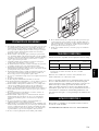
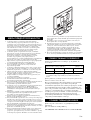
Größe der kompatiblen Fernsehgeräte: bis zu 52 Zoll, unter 45 kg
* Konform mit dem VESA-Montageschnittstellen-Standard und mit dem
Abstand der oben beschriebenen Montagebohrungen.
Der Durchmesser der der Schrauben kann bis zu 8 mm betragen (der
Durchmesser der mitgelieferten Schrauben beträgt 5 mm, 6 mm und 8 mm).
Schlagen Sie vor der Installation in der Gebrauchsanweisung Ihres
Fernsehgeräts nach oder messen Sie den Abstand der
Montagebohrungen an der Rückseite Ihres Fernsehgeräts und
überprüfen Sie, ob sich Ihr Fernsehgerät montieren lässt. Beachten
Sie, dass selbst wenn der Abstand der Montagebohrungen Ihres
Fernsehgeräts identisch mit dem oben beschriebenen Abstand ist, es
dennoch möglich sein kann, dass Sie Ihr Fernsehgerät nicht
installieren können, wenn sich ein hervorragendes Teil oder eine Ein-
/Ausgangsbuchse innerhalb des für die Befestigung des Halters
vorgesehenen Bereichs befindet oder der Halter die Belüftung des
Fernsehgeräts behindert.
Dieses Produkt ist mit den folgenden Lautsprecher-Modellen
kompatibel.
(Stand: Oktober 2009)
YSP-4000/3000, YSP-5100/4100, YAS-81/71, YHT-S1400/S400
SICHERHEITSHINWEISE
KOMPATIBLE FERNSEHGERÄTE
Kompatibler Abstand zwischen den Montagebohrungen an der Rückseite
des Fernsehgeräts (B × H)* Einheit = cm
20 × 20 30 × 20 30 × 30 40 × 20
40 × 30 40 × 40 50 × 20 60 × 40
KOMPATIBLE LAUTSPRECHER

ii De
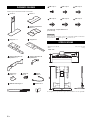
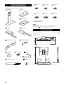
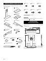
Überprüfen Sie, ob Sie die folgenden Teile erhalten haben.
In der folgenden Montageanleitung werden diese mitgelieferten Teile als
(Teile) bzw. (Schrauben) etc. bezeichnet.
• Abmessungen (B × H × T) .................................................... 650 × 867 × 398 mm
• Gewicht ....................................................................................................... 17,0 kg
Änderungen, die dem technischen Fortschritt dienen, bleiben vorbehalten.
LIEFERUMFANG
: Ständer × 1 : Sockel × 1
: TV-Halter × 1
: Halter L × 1 : Halter R × 1
: Lautsprecher-Halter A × 1 : Lautsprecher-Halter B × 1
: L-Halter × 1 : Kabel-Clips × 4 : Draht × 1
: Montageschablone × 1 : Distanzstück × 1
Hinweis
TECHNISCHE DATEN
(M5 × 16) × 7 (M5 × 16) × 7 (M5 × 20) × 8
(M6 × 16) × 8 (M6 × 20) × 4 (M8 × 20) × 4
Ersatzschrauben: von jeder Größe × 1
(6 Schrauben insgesamt)
Einheit: mm
Weiter mit Seite 1
☞

i Sv
Svenska
1 Installationen av denna enhet kräver ett noga utfört arbete, och tänk så
säkerheten under monteringen. Läs dessa installationsanvisningar innan
du börjar monterings- och installationsarbetet. Yamaha tar inget ansvar
för eventuella olyckor eller skador som kan uppstå genom oaktsamhet
under montering, installation och användning av denna produkt.
2 Installera denna enhet på en plan och stabil plats som håller för vikten.
Om du installerar denna enhet på en instabil plats, exempelvis en matta,
bör du placera en skiva under enheten. Om den installeras på en dålig
plats kan TV:n/högtalaren välta och falla ner och ge upphov till
personskada.
3 När du installerar denna enhet bör du vidta åtgärder så att den inte kan
falla genom att fästa en vajer eller L-fästet.
4 Installera inte enheten mot en skjutdörr, en partition eller på annat ställe
som inte är tillräckligt stabilt.
5 Se till att installationen utförs av minst två personer. När enheten flyttas,
lyft upp den med bottenplattan och bär den. Om du lyfter på annat ställe
än vid bottenplattan kan enheten skadas.
6 Se till att använda alla skruvar och/eller monteringskomponenter som
anges i installationsanvisningarna. Dra åt alla skruvar i den riktning som
anges.
7 Luta eller placera inte föremål i hörnet av TV:n/högtalaren.
8 Skaka eller slå inte på enheten.
9 Gör inga förändringar på delar och använd inga delar som är sönder.
10 Installera inte på en fuktig eller dammig plats, eller där din TV/högtalare
utsätts för ånga eller oljig rök.
11 Installera enheten i ett välventilerat, svalt, torrt och rent ställe. Se
bruksanvisningen för din TV/högtalare för minsta avstånd för tillräcklig
ventilation.
12 Montera din TV/högtalare rätt. Om du inte gör det kan TV:n/högtalaren
välta och falla ner och ge upphov till personskada.
13 Använd den inte på ett vått eller vaxat golv. Om denna produkt används
på en sådan plats kan den fastna mot golvet.
14 Installera på en plats som inte blir för varm. Om den installeras under
direkt solljus eller i närheten av ett element kan det uppstå bubblor,
flagning eller missfärgning på målade ytor.
15 Applicera inte tejp eller annat självhäftande material på målade ytor
eftersom färgen kan lossna.
16 Använd en torr trasa för att avlägsna damm och smuts. Om enheten är
mycket smutsig kan du fukta en trasa med ett neutralt rengöringsmedel
och vatten och vrida ur trasan innan den används på enheten. Observera
att produkter som bensen, målarthinner eller hushållsvax kan få färgen att
blekas och/eller skada ytan.
17 Undvik att tappa vassa föremål på enheten eftersom de kan ge upphov till
skador.
18 Dessa installationsanvisningar ger förklaringar på viktiga
säkerhetsåtgärder som bör beaktas för att undvika skador, samt hur
enheten monteras och installeras. Titta även i bruksanvisningen för din
TV och högtalare under installationen och skaffa dig en bra förståelse
innan du går vidare enligt dessa anvisningar.
19 Förvara bruksanvisningen nära till hands för framtida referens när du har
läst den.
Kompatibelt TV-format: upp till 52 tum, under 45 kg
* Kompatibel med VESA monteringsstandard och med avståndet mellan
monteringshålen enligt ovan.
Diametern på skruvarna bör vara upp till 8 mm (diametern på de medföljande
skruvarna är 5 mm, 6 mm, 8 mm).
Läs bruksanvisningen för din TV före installationen och mät
avståndet mellan monteringshålen på TV:ns baksida för att
kontrollera att det är möjligt att installera den. Observera att trots att
avståndet på monteringshålen på din TV stämmer med avstånden
enligt ovan, kan det förekomma fall då TV:n inte kan monteras på
grund av att det sticker ut en kontakt eller liknande på TV:ns baksida
där fästena ska sitta eller om fästena blockerar ventilationshålen på
TV:n.
Denna produkt är kompatibel med följande modeller av högtalare.
(Oktober, 2009)
YSP-4000/3000, YSP-5100/4100, YAS-81/71, YHT-S1400/S400
SÄKERHETSFÖRESKRIFTER
KOMPATIBEL TV
Kompatibelt avstånd mellan monteringshålen på TV:ns baksida (B × H)*
enhet = cm
20 × 20 30 × 20 30 × 30 40 × 20
40 × 30 40 × 40 50 × 20 60 × 40
KOMPATIBEL HÖGTALARE

ii Sv
Kontrollera att du har följande detaljer.
I följande monteringsprocedur, beskrivs medföljande delar som för delar
och för skruvar, etc.
• Mått (B × H × D)................................................................... 650 × 867 × 398 mm
• Vikt..............................................................................................................17,0 kg
Design och specifikationer kan komma att ändras utan föregående
meddelande.
MEDFÖLJANDE DELAR
: Sockel × 1 : Bottenplatta × 1
: TV-fäste × 1
: Fäste L × 1 : Fäste R × 1
: Högtalarfäste A × 1 : Högtalarfäste B × 1
: L-fäste × 1 : Kabelklips × 4 : Vajer × 1
: Monteringsmall × 1 : Distans × 1
Anmärkning
SPECIFIKATIONER
(M5 × 16) × 7 (M5 × 16) × 7 (M5 × 20) × 8
(M6 × 16) × 8 (M6 × 20) × 4 (M8 × 20) × 4
Reserv: Varje storlek × 1
(6 skruvar totalt)
Enhet: mm

1 De/Sv
Deutsch Svenska
MONTAGE/MONTERING
1-1 1-2
• y Verweist auf einen Tipp bezüglich der Vorgehensweise.
• Notieren Sie im Abschnitt NOTIZEN die während der Montage gemessenen
Abmessungen und die Nummer (auf der Montageschablone).
• Die Installationsarbeiten müssen von mindestens
2 Personen durchgeführt werden.
• Legen Sie vor dem Zusammenbau einen
Kreuzschlitzschraubenzieher bereit, der in die
Schrauben passt.
• Falls Sie das Teil oder das Fernsehgerät mit mehr als
4 Schrauben sichern, ziehen Sie alle Schrauben zunächst
nur halb an und ziehen Sie dann die Schrauben in
diagonaler Reihenfolge fest.
1-1 Befestigen Sie mittels (7 Schrauben) an
.
1-2 Befestigen Sie mittels (3 Schrauben).
Deutsch
Vor der Montage
Hinweise
1 Montage des Ständers
• y indikerar ett brukstips.
• Notera i MEMO-rutan måtten och numret (på monteringsmallen) som mätts
upp under monteringen.
• Se till att utföra den här monteringen med minst
2 personer.
• Kontrollera att du har en Phillips skruvmejsel som passar
till skruvarna före monteringen.
• Om du fäster delar eller TV:n med mer än 4 skruvar, dra
åt alla skruvarna temporärt till hälften, dra sedan åt dem
ordentligt diagonalt.
1-1 Fäst mot med (7 skruvar).
1-2 Fäst med (3 skruvar).
Svenska
Före montering
Anmärkningar
1 Montering av sockeln

MONTAGE/MONTERING
2 De/Sv
Decke oder Ähnliches
Filt etc.
Fernsehständer
TV-stativ
2-1 2-2
X
Y
Ziehen Sie auch die Gebrauchsanleitung Ihres Fernsehgeräts zu Rate.
2-1 Entfernen Sie den Ständer vom Fernsehgerät.
1 Legen Sie eine Decke oder Ähnliches auf einen flachen
Untergrund und legen Sie das Fernsehgerät so auf die
Decke, dass der Bildschirm nicht beschädigt wird.
2 Entfernen Sie den Ständer vom Fernsehgerät.
Das Verfahren zum Entfernen des Ständers variiert abhängig vom
Fernsehgerät. Ausführliche Informationen finden Sie in der
Gebrauchsanleitung Ihres Fernsehgeräts.
2-2 Messen Sie den Abstand (X und Y) und den
Durchmesser der Montagebohrungen an der
Rückseite Ihres Fernsehgeräts.
1
Messen Sie X und Y mittels oder einem anderen Messgerät.
Falls sich Schrauben in den Bohrungen befinden, entfernen Sie diese.
2 Ermitteln Sie den Durchmesser der Montagebohrungen
des Fernsehgeräts.
Verwenden Sie abhängig vom Durchmesser die folgenden
Schrauben:
5 mm: (4 Schrauben)
6 mm: (4 Schrauben)
8 mm: (4 Schrauben)
NOTIZEN
• Ermitteln Sie vor der Installation die Tiefe der Montagebohrungen des
Fernsehgeräts. Falls die mitgelieferten Schrauben nicht passen, verwenden
Sie Unterlegscheiben oder andere, handelsübliche Schrauben.
• Halten Sie Schrauben bereit, die mindestens 5 Umdrehungen
festgezogen werden können.
• Achten Sie auf die Schraubenlänge, wenn der Rand der
Schraubenbohrungen nach unten nachgibt. Ziehen Sie die
Schrauben nicht zu fest, da dies zu einer Verformung des
Fernsehgeräts oder anderen Beschädigungen führen kann.
Deutsch
2 Installieren des Fernsehgeräts
Hinweis
Hinweis
Hinweis
XYSchraube
cm cm
Hinweise
Se också bruksanvisningen för din TV.
2-1 Ta av TV-stativet.
1 Lägg en filt eller liknande på en plan yta, och placera
TV:n på den så att skärmen inte skadas.
2 Ta av TV-stativet.
Metoden att ta ner stativet varierar beroende på TV:n. För mer
information, se bruksanvisningen för din TV.
2-2 Mät avståndet (X och Y) och diametern på
monteringshålen på TV:ns baksida.
1 Mät X och Y med eller något annat mätinstrument.
Om skruvarna sitter i skruvhålen, ta bort dem.
2 Kontrollera diametern för TV:ns monteringshål.
Använd följande skruvar beroende på diametern:
5 mm: (4 skruvar)
6 mm: (4 skruvar)
8 mm: (4 skruvar)
MEMO
• Kontrollera djupet på TV:ns monteringshål före monteringen. Om
medföljande skruvar inte passar, använd brickor eller skruvar som
finns att köpa i butik.
• Se till att skruvarna kan dras åt minst 5 varv.
• Var försiktig med skruvarnas längd om skruvar och skruvhålen är
försänkta. Skruva inte heller åt skruvarna för hårt eftersom det kan
medföra att TV:n blir skev eller att den skadas.
Svenska
2 Montera TV:n
Anmärkning
Anmärkning
Anmärkning
XYSkruv
cm cm
Anmärkningar

MONTAGE/MONTERING
3 De/Sv
Deutsch Svenska
Bei Verwendung von
När du använder
Bei Verwendung von /
När du använder /
2-3
In Schritt 2-2-2 ermittelte Schrauben
Skruvar som har kontrollerats i 2-2-2
*
2
*
1
2-3 Befestigen Sie und .
Die Bohrungen für und variieren abhängig von den in
Schritt 2-2-2 ermittelten Schrauben. Siehe *1 in der
Abbildung oben.
Falls und sich berühren, wenn Sie sie auf das
Fernsehgerät legen (falls die in Schritt 2-2-1 ermittelte
Länge für X 20 cm beträgt), kehren Sie die Position von
und um. Siehe *2 in der Abbildung oben.
Ziehen Sie die Abbildung oben zu Rate und befestigen Sie
und .
Die Pfeile an und müssen zur Oberkante des Fernsehgeräts
zeigen.
Deutsch
Hinweis
2-3 Fäst och .
Hålen för och varierar beroende på skruvarna som
kontrollerades i steg 2-2-2. Se *1 i figuren ovan.
Om och rör vid varandra när du placerar dem på TV:n
(om X som kontrollerades i steg 2-2-1 är 20 cm), kasta om
läget på och . Se *2 i figuren ovan.
Se figuren ovan, och fäst och .
Pilarna på och ska vara mot TV:ns övre del.
Svenska
Anmärkning

MONTAGE/MONTERING
4 De/Sv
2-4
D. h., bei Verwendung des YSP-4100
Dvs, när du använder YSP-4100
2-4 Ermitteln Sie die Position zur Befestigung von
am Fernsehgerät.
1 Positionieren Sie entsprechend über der
Montagebohrung A an bzw. , so dass die Bohrung
an an der Montagebohrung A an bzw.
ausgerichtet ist (siehe Abbildung).
2 Ermitteln Sie, welche Zahl an sich an der Unterseite
Ihres Fernsehgeräts befindet. Ermitteln Sie die Nummer
auf der Leiste, die der Bezeichnung Ihres Lautsprechers
entspricht.
Wenn keine Nummer für Ihren Lautsprecher vorhanden
ist, richten Sie an der Montagebohrung B aus und
ermitteln Sie dann erneut die Nummer.
NOTIZEN
3 Ziehen Sie (2 Schrauben) provisorisch etwa
5 Umdrehungen an den Bohrungen auf derselben Höhe
wie die in Schritt 2 ermittelte Nummer fest.
Deutsch
Nummer
2-4 Kontrollera läget för fäste av och TV:n.
1 Placera över monteringshål A på eller så att
hålet på är rakt över monteringshålet A på eller
,
enligt figuren.
2 Kontrollera vilket nummer på som är på TV:ns
undersida. Se numret som visas på listen som motsvarar
namnet på din högtalare.
Om det inte finns något nummer som hänför sig till din
högtalare, rikta in med monteringshålet B, och
kontrollera numret igen.
MEMO
3 Dra åt (2 skruvar) temporärt ca 5 varv i hålen på
samma höjd som motsvarande nummer du kontrollerade i
2.
Svenska
Nummer
Sayfa yükleniyor...
Sayfa yükleniyor...
Sayfa yükleniyor...
Sayfa yükleniyor...
Sayfa yükleniyor...
Sayfa yükleniyor...
Sayfa yükleniyor...
Sayfa yükleniyor...
Sayfa yükleniyor...
Sayfa yükleniyor...
Sayfa yükleniyor...
Sayfa yükleniyor...
Sayfa yükleniyor...
Sayfa yükleniyor...
Sayfa yükleniyor...
Sayfa yükleniyor...
Sayfa yükleniyor...
Sayfa yükleniyor...
Sayfa yükleniyor...
Sayfa yükleniyor...
Sayfa yükleniyor...
Sayfa yükleniyor...
Sayfa yükleniyor...
Sayfa yükleniyor...
Sayfa yükleniyor...
Sayfa yükleniyor...
Sayfa yükleniyor...
Sayfa yükleniyor...
-
 1
1
-
 2
2
-
 3
3
-
 4
4
-
 5
5
-
 6
6
-
 7
7
-
 8
8
-
 9
9
-
 10
10
-
 11
11
-
 12
12
-
 13
13
-
 14
14
-
 15
15
-
 16
16
-
 17
17
-
 18
18
-
 19
19
-
 20
20
-
 21
21
-
 22
22
-
 23
23
-
 24
24
-
 25
25
-
 26
26
-
 27
27
-
 28
28
-
 29
29
-
 30
30
-
 31
31
-
 32
32
-
 33
33
-
 34
34
-
 35
35
-
 36
36
-
 37
37
-
 38
38
-
 39
39
-
 40
40
-
 41
41
-
 42
42
-
 43
43
-
 44
44
-
 45
45
-
 46
46
-
 47
47
-
 48
48


diğer dillerde
- español: Yamaha YTS-T500 Manual de usuario
- français: Yamaha YTS-T500 Manuel utilisateur
- italiano: Yamaha YTS-T500 Manuale utente
- svenska: Yamaha YTS-T500 Användarmanual
- Deutsch: Yamaha YTS-T500 Benutzerhandbuch
- English: Yamaha YTS-T500 User manual
- dansk: Yamaha YTS-T500 Brugermanual
- русский: Yamaha YTS-T500 Руководство пользователя
- suomi: Yamaha YTS-T500 Ohjekirja
- Nederlands: Yamaha YTS-T500 Handleiding
- română: Yamaha YTS-T500 Manual de utilizare
