Magmaweld RS 250 M El kitabı
- Kategori
- Kaynak Sistemi
- Tip
- El kitabı
Bu kılavuz aynı zamanda aşağıdakiler için de uygundur:

RS 200 M
RS 250 M
RS 300 M
(+90) 444 93 53
magmaweld.com
info@magmaweld.com (+90) 538 927 12 62
USER MANUAL

All rights reserved. It is prohibited to reproduce this documentation, or any part thereof, without the prior written
Magma Mekatronik may modify the information and the images without any prior notice.

FR
RU
TR
EN
MIG/MAG WELDING MACHINE
3

4RS 200 M / RS 250 M / RS 300 M
EN
www.magmaweld.comUSER MANUAL
1
1.1
1.2
1.3
1.4
1.5
2
2.1
2.2
2.3
2.4
2.4.1
2.4.2
2.4.3
2.4.4
3
3.1
3.2
3.3
3.4
3.5
3.6
3.7
3.8
4
4.1
4.2
4.3
4.4
4.5
5
5.1
5.2
5.3
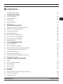
SAFETY PRECAUTIONS
TECHNICAL INFORMATION
General Information
Machine Components
Product Label
Technical Data
Accessories
Delivery Control
Installation and Operation Recommendations
Mains Plug Connection
Welding Connections
Connections of the Wire Feeder
Grounding Pliers Connections
Connections for Long Harness
Gas Connections
OPERATION
Connection to Mains
Preparation and Connection of the Torch
Selection and Replacement of Wire Feed Rollers
Placing the Wire Spool and Wire Feeding Process
Adjustment of Gas Flow
Using Trigger Modes
Starting and Ending the Welding Process
Welding Parameters
Maintenance
Non-Periodic Maintenance
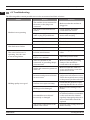
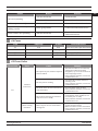
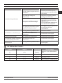
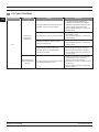
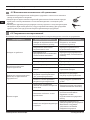
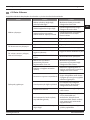
Troubleshooting
Fuses
Error Codes
ANNEX
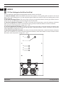
Fine Settings in the Wire Feed Unit
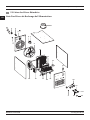
Spare Parts Lists
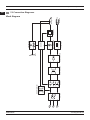
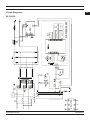
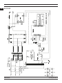
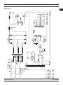
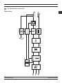
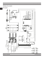
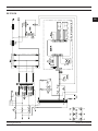
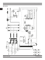
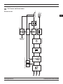
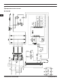
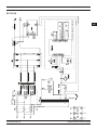
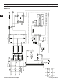
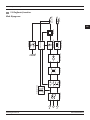
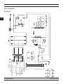
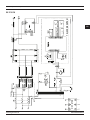
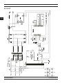
Connection Diagrams
5
11
11
12
13
14
16
16
17
17
17
17
18
18
19
19
20
21
22
22
23
24
25
25
26
27
27
28
29
32
Contents

5RS 200 M / RS 250 M / RS 300 M
EN
www.magmaweld.com USER MANUAL
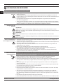
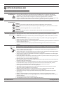
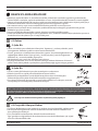
Be Sure To Follow All Safety Rules In This Manual!
• Safety symbols found in the manual are used to identify potential hazards.
• When any one of the safety symbols are seen in this manual, it must be understood that there is
a risk of injury and the following instructions should be read carefully to avoid potential hazards.
• The possessor of the machine is responsible for preventing unauthorized persons from
accessing the equipment.
• Persons using the machine must be experienced or fully trained in welding / cutting they have to
read the user manual before operation and follow the safety instructions.
Explanation Of Safety
Information
• Read the user manual, the label on the machine and the safety instructions carefully.
• Make sure that the warning labels on the machine are in good condition. Replace missing and
damaged labels.
• Learn how to operate the machine, how to make the checks in a correct manner.
• Use your machine in suitable working environments.
• Improper changes made in your machine will negatively affect the safe operation and its
longevity.
• The manufacturer is not responsible for the consequences resulting from the operation of the
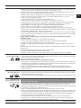
Comprehending Safety
Precautions
Explanation Of Safety
Symbols
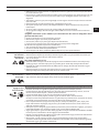
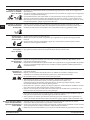
ATTENTION
Indicates a potentially hazardous situation that could cause injury or damage.
In case if no precaution is taken, it may cause injuries or material losses / damages.
IMPORTANT
DANGER
Indicates a serious danger. In case if not avoided, severe or fatal injuries may occur.
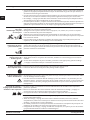
Make certain that the installation procedures comply with national electrical standards
persons.
• Wear dry and sturdy insulated gloves and working apron. Never use wet or damaged gloves and
working aprons.
operator must be protective against sparks, splashing and arc radiation.
• Do not work alone. In case of a danger make sure you have someone for help in your working
environment.
• Do not touch the electrode with the bare hand. Do not allow the electrode holder or electrode to
come in contact with any other person or any grounded object.
• Never touch parts that carry electricity.
• Never touch the electrode if you are in contact with the electrode attached to the work surface,
material that is large enough to cut off the operator’s contact with the work surface.
• Do not connect more than one electrode to the electrode holder.
• Clamp work cable with good metal-to-metal contact to workpiece or worktable as near the weld
as practical.
• Check the torch before operating the machine. Make sure the torch and its cables are in good
condition. Always replace a damaged, worn torch.
• Do not touch electrode holders connected to two machines at the same time since double
open-circuit voltage will be present.
• Keep the machine turned off and disconnect cables when not in use.
• Before repairing the machine, remove all power connections and / or connector plugs or turn
off the machine.
• Be careful when using a long mains cable.
Electric Shocks
May Kill

6RS 200 M / RS 250 M / RS 300 M
EN
www.magmaweld.comUSER MANUAL
• Turn off the electric power.
• Use non-conducting material, such as dry wood, to free the victim from contact with live parts
or wires.
• Call for emergency services.
• If the victim is not breathing, Administer cardiopulmonary resuscitation (CPR) immediately
after breaking contact with the electrical source. Continue CPR (cardiac massage) until
breathing starts or until help arrives.
• Treat an electrical burn as a thermal burn by applying sterile, cold (iced) compresses. Prevent
contamination, and cover with a clean, dry dressing.
Procedures for
Electric Shock
Long-term inhalation of fumes and gases released from welding / cutting is very dangerous.
• Keep away from the moving parts.
closed and in locked position.
• Wear metal toe shoes against the possibility of heavy objects falling on to your feet.
• Burning sensations and irritations in the eyes, nose and throat are signs of inadequate
ventilation. In such a case, immediately boost the ventilation of the work area, and if the
problem persists, stop the welding / cutting process completely.
• Use a suitable fume extraction system where welding / cutting works are being carried out. If
necessary, install a system that can expel fumes and gases accumulated in the entire workshop.
cadmium, zinc, coated or painted materials, use masks that provide fresh air in addition to the
above precautions.
• If the gas tanks are grouped in a separate zone, ensure that they are well ventilated, keep the
main valves closed when gas cylinders are not in use, pay attention to possible gas leaks.
• Shielding gases such as argon are denser than air and can be inhaled instead of air if used in
• Do not perform welding / cutting operations in the presence of chlorinated hydrocarbon vapors
released during lubrication or painting operations.
• Some welded / cut parts require special ventilation. The safety rules of products that require
special ventilation should be read carefully. A suitable gas mask should be worn when
necessary.
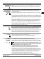
Fumes and Gases
May Be Harmful To
Your Health
Moving Parts May
Cause Injuries
Make sure all connections are tight, clean, and dry.
• Keep cables dry, free of oil and grease, and protected from hot metal and sparks.
• Bare wiring can kill. Check all cables frequently for possible damage. If a damaged or an
uninsulated cable is detected, repair or replace it immediately.
• Insulate work clamp when not connected to workpiece to prevent contact with any metal
object.
• Make sure that the grounding of the power line is properly connected.
• Use AC output ONLY if required for the welding process.
• If AC output is required, use remote output control if present on unit.
• in damp locations or while wearing wet clothing,
• when in cramped positions such as sitting, kneeling, or lying,
• when there is a high risk of unavoidable or accidental contact with the workpiece or ground.
For these conditions, use the following equipment in order presented:
• Semiautomatic DC constant voltage (CV) MIG welding machine,
• DC manual MMA welding machine,
• DC or AC welding machine with reduced open-circuit voltage (VRD), if available.

7RS 200 M / RS 250 M / RS 300 M
EN
www.magmaweld.com USER MANUAL
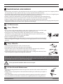
• Performing works such as welding / cutting, surface grinding, and brushing cause sparks and
metal particles to splatter. Wear approved protective work goggles which have edge guards
under the welding masks to prevent sustaining possible injuries.
Sparks and Spattering
Particles May Get
Into Eyes and Cause
Damage
• Do not touch the hot parts with bare hands.
• Wait until the time required for the machine to cool down before working on its parts.
• If you need to hold hot parts, use suitable tools, welding / cutting gloves with high-level thermal
Hot Parts May Cause
Severe Burns
• Protect other naked parts of your body (arms, neck, ears, etc.) with suitable protective clothing
from these rays.
so that people around you will not sustain injuries from arc rays and hot metals.
• This machine is not used for heating of icebound pipes. This operation performed with the
Arc Light May Damage
Your Eyes and Skin
• The noise generated by some equipment and operations may damage your hearing ability.
• Wear approved personal ear protective equipment if the noise level is high.
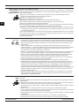
Noise May Cause
Damage To Your
Hearing Ability
• Do not apply welding / cutting operations into completely closed tanks or pipes.
• Before welding to tanks and closed containers, open them, completely empty them, and clean
them. Pay the greatest attention possible to the welding / cutting operations you will perform in
such places.
• Do not weld in tanks and pipes which might have previously contained substances that may
• Welding / cutting equipment heats up. For this reason, do not place it on surfaces that could
easily burn or be damaged !
• Do not point the torch towards any part of the body, other persons, or any metal while
unwrapping the welding / cutting wire.
• When welding wire is run manually from the roller especially in thin diameters the wire can slip
out of your hand, like a spring or can cause damage to you or other people around, therefore you
must protect your eyes and face while working on this.
Welding Wires Can
Cause Injuries
explosions.
• Before starting the welding / cutting work, remove these materials form the environment or cover
• National and international special rules apply in these areas.
Welding Operations
May Cause Fire and
Explosion
extinguishers tubes, water, and sand in easily accessible places.
circuits. Make sure that they are periodically inspected and pay attention that they run reliably.
• Electrical equipment should not be repaired by unauthorized persons.
Errors occurred if failed to do so may result in serious injury or death when using the
equipment.
• The gas circuit elements operate under pressure; explosions may occur as a result of services
provided by unauthorized persons, users may sustain serious injuries.
• It is recommended to perform technical maintenance of the machine and its auxiliary units at
least once a year.
Maintenance Work
Persons To Machines
and Apparatus May
Cause Injuries

8RS 200 M / RS 250 M / RS 300 M
EN
www.magmaweld.comUSER MANUAL
operations, accompanied by another person.
• Avoid performing welding / cutting operations in such enclosed areas as much as possible.
• Take all necessary precautions when moving the machine. The areas where the machine to be
transported, parts to be used in transportation and the physical conditions and health of the
person carrying out the transportation works should be suitable for the transportation process.
• Some machines are extremely heavy; therefore, make sure that the necessary environmental
safety measures are taken when changing their places.
• If the machine is to be used on a platform, it must be checked that this platform has suitable load
bearing limits.
• If it is to be transported by means of a haulage vehicle (transport trolley, forklift etc.), make sure
of the durableness of the vehicle, and the connection points (carrying suspenders, straps, bolts,
nuts, wheels, etc.) that connect the machine to this vehicle.
• If the machine will be carried manually, make sure the durableness of the machine apparatuses
(carrying suspenders, straps, etc.) and connections.
• Observe the International Labor Organization’s rules on carriage weights and the transport
regulations in force in your country in order to ensure the necessary transport conditions.
• Always use handles or carrying rings when relocating the power-supply sources. Never pull
from torches, cables or hoses. Be absolutely sure to carry gas cylinders separately.
• Remove all interconnections before transporting the welding / cutting equipment, each being
separately, lift and transport small ones using its handles, and the big ones from its handling
rings or by using appropriate haulage equipment, such as forklifts.
Welding / Cutting in
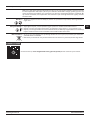
Failure To Take
Precautions During
Transport May Cause
Accidents
of tripping over on cables and hoses; yet, large, easily ventilatable, dust-free areas. To prevent
way that they would not tip over for sure.
• Allow operators to easily access settings and connections on the machine.
Falling Parts May
Cause Injuries Improper positioning of the power-supply sources or other equipment can cause serious injury
to persons and physical damage to other objects.
• Allow the machine to cool down according to operation cycle rates.
• Reduce the current or operation cycle rate before starting the welding / cutting again.
• Do not block the fronts of air vents of the machines.
Excessive Use Of The
Machine Causes
Overheating
Excessive Use Of The
Machine Causes
Overheating
• This device is in group 2, class A in EMC tests according to TS EN 55011 standard.
• This class A device is not intended for use in residential areas where electrical power is supplied
compatibility due to radio frequency interference transmitted and emitted in such places.
• Make sure that the work area complies with electromagnetic compatibility (EMC).
Electromagnetic interferences during welding / cutting operations may cause undesired effects
on your electronic devices and network; and the effects of these interferences that may occur
during these operations are under the responsibility of the user.
• If there is any interference, to ensure compliance; extra measures may be taken, such as the
use of short cables, use of shielded (armored) cables, transportation of the welding machine to
the work area under protection in terms of EMC.
• To avoid possible EMC damage, make sure to perform your welding / cutting operations as far
away from your sensitive electronic devices as possible (100 m).
This device is not compliant with IEC 61000 -3-12. In case if it is desired to be
connected to the low voltage network used in the home, the installer to make the
electrical connection or the person who will use the machine must be aware that
the machine has been connected in such a manner; in this case the responsibility
belongs to the user.

9RS 200 M / RS 250 M / RS 300 M
EN
www.magmaweld.com USER MANUAL
• Ensure that your welding and/or cutting machine has been installed and situated in its place
according to the user manual.
Before installing the welding / cutting equipment, the person in charge of the operation and / or
the user must conduct an inspection of possible electromagnetic interference in the environment.
Aspects indicated below has to be taken into consideration;
a) Other supply cables, control cables, signal and telephone cables, above and below the welding
/ cutting machine and its equipment,
b) Radio and television transmitters and receivers,
c) Computer and other control hardware,
d) Critical safety equipment, e.g. protection of industrial equipment,
e) Medical apparatus for people in the vicinity, e.g. pacemakers and hearing aids,
f) Equipment used for measuring or calibration,
g) Immunity of other equipment in the environment. The user must ensure that the other
equipment in use in the environment is compatible. This may require additional protection
measures.
Considering the time during which the welding / cutting operations or other activities take
place during the day, the boundaries of the investigation area can be expanded according to the
size of the building, the structure of the building and other activities that are being performed
in the building.
for solving the interfering effect. In case if deemed necessary, on-site measurements can also be
(Source: IEC 60974-9).
• The appliance must be connected to the electricity supply in the recommended manner by a
tube or with an equivalent shielded cable. The housing of the power supply must be connected
and a good electrical contact between these two structures has to be provided.
• The recommended routine maintenance of the appliance must be carried out. All covers on the
body of the machine must be closed and / or locked when the device is in use. Any changes,
other than the standard settings without the written approval of the manufacturer, cannot be
possibly occur.
the work area, in a side by side manner. Welding / cutting cables should not be wound in any
way.
machine to pull metal parts on to itself. To avoid this attraction, make sure that the metal
interconnected metal materials.
• In cases where the workpiece cannot be connected to the ground due to electrical safety, or
because of its size and position (for example, in building marine vessel bodies or in steel
construction manufacturing), a connection between the workpiece and the grounding may
reduce emissions in some cases, it should be kept in mind that grounding of the workpiece may
cause users to sustain injuries or other electrical equipment in the environment to break down.
In cases where necessary, the workpiece and the grounding connection can be made as a direct
connection, but in some countries where direct connection is not permissible, the connection
can be established using appropriate capacity elements in accordance with local regulations
and ordinances.
• Screening and shielding of other devices and cables in the work area can prevent aliasing
applications.
Evaluation Of
Electromagnetic
Suitability Of The
Work Area
Electromagnetic
Interferance
Reduction Methods
(EMF).
All operators must follow the following procedures to minimize the risk of exposure to EMF;
secured as far as possible with the joining materials (tape, cable ties etc.).
• The operator’s body and head should be kept as far away from the welding / cutting machine
and cables as possible,
Electromagnetic Field
(EMF)

10 RS 200 M / RS 250 M / RS 300 M
EN
www.magmaweld.comUSER MANUAL
• Choose the welding / cutting method and welding machine for the welding work you are to
perform.
• Select the welding / cutting current and/or voltage to match the material and thickness you are
going to weld.
• If you have to wait for a long time before you start your welding / cutting work, turn off the machine
after the fan has cooled it down. Our machines with smart fan control will turn off on their own.
• This device is not domestic waste. It must be directed to recycling within the framework of the
European Union directive and national laws.
• Obtain information from your dealer and authorized persons about the waste management of
your used machines.
Waste Procedure
(EMF).
All operators must follow the following procedures to minimize the risk of exposure to EMF;
secured as far as possible with the joining materials (tape, cable ties etc.).
• The operator’s body and head should be kept as far away from the welding / cutting machine
and cables as possible,
• Welding / cutting and electric cables should not be wrapped around the body of the machine in
any way,
• The body of the machine should not get caught between the welding / cutting cables. The source
cables must be kept away from the body of the machine, both being placed side by side,
• The return cable must be connected to the workpiece as close as possible to the work area,
• The welding / cutting machine should not rest against the power unit, ensconce on it and not
work too close to it,
• Welding / cutting work should not be performed when carrying the wire supply unit or power
unit.
EMF may also disrupt the operation of medical implants (materials placed inside the body), such
as pacemakers. Protective measures should be taken for people who carry medical implants. For
example, access limitation may be imposed for passers-by, or individual risk assessments may be
conducted for welders. Risk assessment should be conducted and recommendations should be
made by a medical professional for users who carry medical implants.
• Do not expose the machine to rain, prevent the machine from splashing water or
pressurized steam.
Protection
WARRANTY FORM
Please visit our website www.magmaweld.com/warranty-form/wr for warranty form.

11RS 200 M / RS 250 M / RS 300 M
EN
www.magmaweld.com USER MANUAL
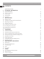
1
7
8
9
10
11
12
13
14
15
16
17
18
19
20
21
22
23
24
16-a 16-b
16-c
2
3
4
5
6
TECHNICAL INFORMATION
1.1 General Information
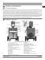
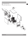
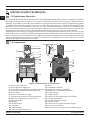
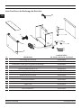
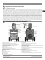
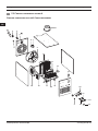
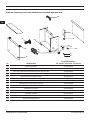
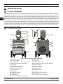
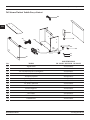
1.2 Machine Components
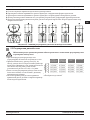
RS 200 M, RS 250 M and RS 300 M are 3 phase step controlled, Constant Voltage industrial MIG/MAG machines
and thermally protected against over heating. The welding voltage adjustment ranges are, for 200 model 14 steps
between 17-36 V, for 250 models 21 steps between 20-51 V, for 300 models 21 steps between 19 - 44 V.
Wire feeding unit is a robust 4 wheel drive system which is designed as a separate box from the power source in
order to cover larger work areas. It contains a wire feeding motor-gearbox assembly, an electronic control card
and a gas valve, therefore this unit should be handled carefully at site. The wheels under the box are for the ease
of the welder to move the box as he welds, but the box shouldn’t be pulled across the work area by the torch. Even
though you can manufacture with these machines in a big range of current scale all day long, model 200 is
optimized for 0.8 mm, 250 for 1.0mm and 300 for 1.0 mm heavy-duty applications.
Torch Connector
Thin Adjustment Switch
On / Off and Coarse Adjustment Switch
Wire Feed Unit Connector
Gas Outlet
Welding Current Plug Socket
Trigger Mode Switch
Wire Speed Adjustment Button
Turn Table
Handle
Lifting Eye
Voltmeter
Ammeter
Workpiece Cable Socket (-)
Wheel
Wire Feeder Harness
Welding Current Plug
Wire Feed Unit Control Cable
Gas Hose
Mains Cable
Drum Feeding Wire Inlet
Insurance Group
CO Heater Socket
Gas Inlet
Gas Cylinder Security Chain
Fan Output
Gas Cylinder Transport Platform

12 RS 200 M / RS 250 M / RS 300 M
EN
www.magmaweld.comUSER MANUAL
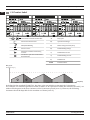
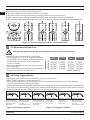
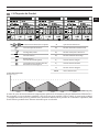
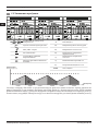
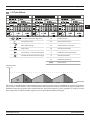
1.3 Product Label
X
U
I
U
U
I
MIG/MAG Welding
Horizontal Characteristic
Mains Input 3-Phase Alternating
Current
Suitable for Operation at Hazardous
Environments
Direct Current
Duty Cycle
Open Circuit Voltage
Rated Welding Current
Mains Voltage and Frequency
Protection Class
Rated Welding Voltage
Rated Power
Rated Mains Current
4 minutes should be kept idle for the machine cool down (zone 2).
6 min. 6 min.6 min.4 min. 4 min. 4 min. Time (min.)

13RS 200 M / RS 250 M / RS 300 M
EN
www.magmaweld.com USER MANUAL
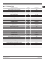
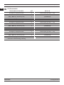
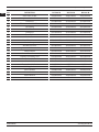
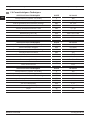
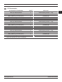
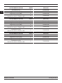
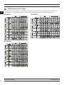
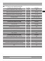
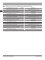
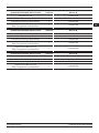
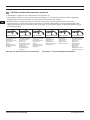
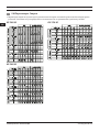
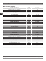
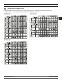
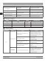
1.4 Technical Data
400
865 x 510 x 780
3 x 7
300
101
19 - 44
IP 21
40 - 300
Mains Voltage (3-Phase 50-60 Hz)
Voltage Adjustment and Number of Levels
Welding Current Range
Protection Class
Rated Power
Dimensions (l x w x h)
Rated Welding Current
Weight
Open Circuit Voltage
TECHNICAL DATA
Mains Voltage (3-Phase 50-60 Hz)
Voltage Adjustment and Number of Levels
Welding Current Range
Protection Class
Rated Power
Dimensions (l x w x h)
Rated Welding Current
Weight
Open Circuit Voltage
TECHNICAL DATA
UNIT
V
VDC
kVA
mm
ADC
ADC
kg
mm
400
865 x 510 x 780
3 x 7
250
101
19.7 - 51
IP 21
57 - 250
UNIT
V
VDC
kVA
mm
ADC
ADC
kg
mm
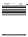
400
865 x 510 x 780
2 x 7
240
101
17 - 36
IP 21
40 - 240
UNIT
V
VDC
kVA
mm
ADC
ADC
kg
mm
Mains Voltage (3-Phase 50-60 Hz)
Voltage Adjustment and Number of Levels
Welding Current Range
Protection Class
Rated Power
Dimensions (l x w x h)
Rated Welding Current
Weight
Open Circuit Voltage
TECHNICAL DATA

14 RS 200 M / RS 250 M / RS 300 M
EN
www.magmaweld.comUSER MANUAL
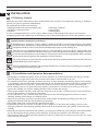
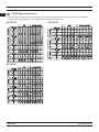
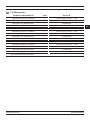
1.5 Accessories
Workpiece Clamp and Cable
Gas Hose
MIG/MAG Mix/Argon Accessory Set*
QTY
1
1
1
1
7905212505 (25 mm² - 5 m)
7920000515
7907000002
7920000510
7905212505 (25 mm² - 5 m)
7920000525
7907000002
7920000520
7905212505 (25 mm² - 5 m)
7920000535
7907000002
7920000530
Workpiece Clamp and Cable
Gas Hose
MIG/MAG Mix/Argon Accessory Set*
QTY
1
1
1
1
Workpiece Clamp and Cable
Gas Hose
MIG/MAG Mix/Argon Accessory Set*
QTY
1
1
1
1

15RS 200 M / RS 250 M / RS 300 M
EN
www.magmaweld.com USER MANUAL
CO Heater
Gas Regulator (Mix)
Gas Regulator (CO)
Lava MIG 25 (3 m) Air Cooled MIG Torch
QTY
1
1
1
1
7020009002
7120025003
7020001005
7020001004
CO Heater
Gas Regulator (Mix)
Gas Regulator (CO)
Lava MIG 25 (3 m) Air Cooled MIG Torch
Lava MIG 35 (3 m) Air Cooled MIG Torch
QTY
1
1
1
1
1
7020009002
7120025003
7120035003
7020001005
7020001004
CO Heater
Gas Regulator (Mix)
Gas Regulator (CO)
Lava MIG 35 (3 m) Air Cooled MIG Torch
QTY
1
1
1
1
7020009002
7120035003
7020001005
7020001004

16 RS 200 M / RS 250 M / RS 300 M
EN
www.magmaweld.comUSER MANUAL
2.1 Delivery Control
Make sure that all the materials you have ordered have been received. If any material is missing or damaged,
contact your place of purchase immediately.
The standard box includes the following;
• Workpiece clamp and cable • User manual
• Gas hose • Welding Wire
In case of a damaged delivery, record a report, take a picture of the damage and report to the transport
company together with a photocopy of the delivery note. If the problem persists, contact the customer service.
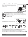
2.2 Installation and Operation Recommendations
• Lifting rings or forklifts should be used to move the machine. Do not lift the machine with the gas cylinder.
Place the power supply on a hard, level, smooth surface where it will not fall or tip over.
• For a better performance, place the machine at least 30 cm away from the surrounding objects. Pay attention
to overheating, dust and moisture near the machine. Do not operate the machine under direct sunlight. If the
• Avoid welding outdoors in windy and rainy weather circumstances. If welding is necessary in such cases,
protect the welding area and the welding machine with a curtain and canopy.
• When positioning the machine, make sure that materials such as walls, curtains, boards do not prevent easy
access to the machine’s controls and connections.
• If you weld indoors, use a suitable fume extraction system. Use breathing apparatus if there is a risk of
damage the machine and this may invalidate the warranty.
• Tighten the ground wire as close as possible to the workpiece. Do not allow the welding current to pass
through equipment other than the welding cables such as the machine itself, gas cylinder, chain and roller
bearing.
• When the gas cylinder is placed on the machine, secure the gas cylinder by connecting the chain immediately.
If you will not place the gas cylinder on the machine, secure the gas cylinder to the wall with a chain.
• The electrical outlet on the back of the machine is for the C0 heater. Never connect a device to the C0 outlet
other than the C0 heater !
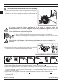
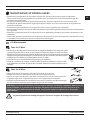
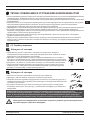
Symbols and their meanings on the device
Welding may be dangerous. Proper working conditions should be ensured and necessary precautions
should be taken. Specialists are responsible for the machine and have to be equipped with the necessary
equipment and those who are not relevant should be kept away from the welding area.
This device is not compatible with IEC 61000-3-12. If it is desired to connect to the low voltage mains used
in homes, it is essential that the installer or the person who will operate the machine to make the electrical
connection has information on the machine’s connectivity. In this case the responsibility will be assumed
by the person who will perform the installation or by the operator.
The safety symbols and warning notes on the device and in the operating instructions must be observed
and the labels must not be removed.
Grids are intended for ventilation. The openings should not be covered in order to provide good cooling and
no foreign objects should be inserted.
Installation

17RS 200 M / RS 250 M / RS 300 M
EN
www.magmaweld.com USER MANUAL
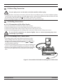
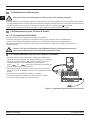
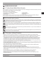
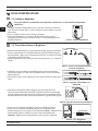
2.3 Mains Plug Connection
For your safety, never use the mains cord of the machine without a plug.
• No plug has been connected to the mains cable since there may different types of outlets available in plants,
the grounding cable marked with and a yellow / green color is present.
• After connecting the plug to the cable, do not attach it to the outlet at this stage.
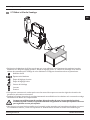
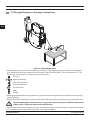
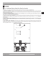
16-a
16-b
16-c
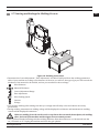
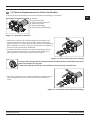
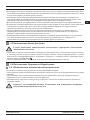
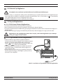
Be sure that the connections are fastened tightly. Loose or incorrect fastening may cause
overheating or gas leakage.
• Place the wire feeder on to the turn table on the machine.
• Connect the blue gas hose to gas outlet bush in front of the power source.
• Connect the control cable to the control socket in front of the power source.
• Connect the welding plug into the welding cable connection outlet in front of the power source.
2.4 Welding Connections
2.4.1 Connections of the Wire Feeder
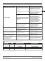
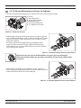
2.4.2 Grounding Pliers Connections
• Grounding cable sockets with different inductance values
allow welding with lower spatter in a wide current range.
Socket for low current and small wire diameters socket,
for high current and large wire diameters or
socket should be preferred.
• Connect the grounding pliers wire to one of the grounding wire
sockets on the machine and tighten by turning it to the right.
pliers to the workpiece as close as possible to the welding
area.
Installation

18 RS 200 M / RS 250 M / RS 300 M
EN
www.magmaweld.comUSER MANUAL
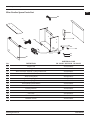
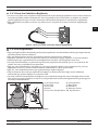
16-c
16-b
16-a
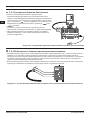
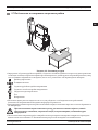
• Machines with harness longer than 5 meter have detachable harness and wire feeding connection in order to
lift easier. Both ends of the harness are the same, therefore sockets and connectors must be connected to the
wire feeding unit same as the connections to the front side of the machine.
• If your machine has harness longer than 5 meter, connect the harness to the wire feeding unit as seen below.
2.4.3 Connections for Long Harness
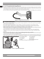
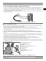
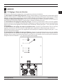
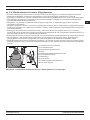
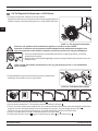
• If you will use the gas cylinder on the gas cylinder transport platform on the machine, place the gas cylinder
here and secure it with a chain.
• If you will not place the gas cylinder on the machine, secure the gas cylinder to the wall with a chain.
• Use safety regulators and heaters according to the standards for work safely to achieve the best results.
• Make sure the size of the hose connection of the gas regulator you are using is 3/8 .
• Open the gas cylinder valve keeping your head and face away from the outlet of the valve and keep it open for
5 seconds. By this means, possible sediment and impurities will be discharged.
• If the CO heater to the gas cylinder. After connecting the gas
regulator to the CO heater, insert the plug of the CO heater into the CO heater outlet on the back of the
machine.
• If the CO heater will not be used, connect the gas regulator directly to the gas cylinder.
• Connect one end of the tube hose to the gas regulator and tighten the clamp. Connect the other end to the gas
inlet at the back of the machine and tighten the nut.
hear a noise and/or detect a smell of gas as a leak indicator, examine your connections and eliminate leakage.
2.4.4 Gas Connections
Gas Cylinder Valve Gas Regulator
Gas Cylinder Manometer
CO Heater Flowmeter
Chain Flow Adjustment Valve
CO Heater Energy CableGas Hose
1
2
5
4
3
6
7 8
9
10
Installation

19RS 200 M / RS 250 M / RS 300 M
EN
www.magmaweld.com USER MANUAL
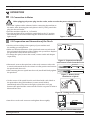
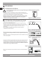
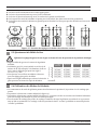
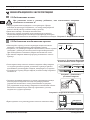
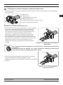
Torch Nut
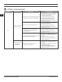
3.2 Preparation and Connection of the Torch
• Check the 3-phase with a voltmeter before connecting the machine to
the mains. After detecting that each phase is 400V (± 40V), attach the
plug into the wall outlet.
• Start the machine with the on / off switch.
• Turn the machine off by turning the switch back to the “0” position
after hearing the fan sound and seeing the ammeter and voltmeter
lights are on.
• Use the torch according to the capacity of your machine and
the welding you will perform.
• Make sure that the diameters of the spiral and contact nozzle inside
the torch match the diameter of the welding wire you will use. Replace
the spiral and contact nozzle if necessary.
• To change the spiral, remove the nozzle, contact nozzle and adapter
respectively.
• Afterwards, remove the spiral nut on the torch connector side with
the spiral inside the torch.
the spiral nut.
• Cut the excess of the spiral from the torch head with a side chisel at
the point where the gas distributor (contact nozzle holder)
immediately ends as shown on the right, so that there is no gap
between the spiral and the contact nozzle. File the cut point to make it
blunt and burr free.
• Attach it to torch torch connector and tighten the nut tightly.
Nozzle
Contact Tip
Adapter
Nut of Liner
Liner
3.1 Connection to Mains
When plugging the power plug into the outlet, make sure that the power switch is set to “0”.
OPERATION

20 RS 200 M / RS 250 M / RS 300 M
EN
www.magmaweld.comUSER MANUAL
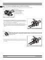
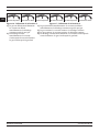
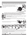
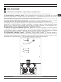
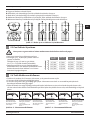
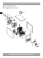
3.3 Selection and Replacement of Wire Feed Rollers
• Open the cover of the wire feed part. You will see the four-roller wire feed system.
Engine
Euro Connector
Pressure Roller Handle
Pressure Rollers
Wire Feed Rollers
WF Roller Screws
1
2
3
4
4
5
5
6
6
• Use wire feed rollers suitable for the material and diameter of
the welding wire you will use. Use V-grooved wire feed rollers for
steel and stainless steel, corrugated V-grooves for cored wires
and U corrugated ones for aluminum.
• If you need to replace the wire feed rollers, pull the pressure
roller lever toward your side and after lifting the pressure rollers,
remove the wire feed roller screws and remove the existing
rollers.
• After inserting the rollers, you will use, re-insert the screws and
lower the pressure rollers and lock the pressure roller lever onto
the rollers.
0.8 mm
Sayfa yükleniyor...
Sayfa yükleniyor...
Sayfa yükleniyor...
Sayfa yükleniyor...
Sayfa yükleniyor...
Sayfa yükleniyor...
Sayfa yükleniyor...
Sayfa yükleniyor...
Sayfa yükleniyor...
Sayfa yükleniyor...
Sayfa yükleniyor...
Sayfa yükleniyor...
Sayfa yükleniyor...
Sayfa yükleniyor...
Sayfa yükleniyor...
Sayfa yükleniyor...
Sayfa yükleniyor...
Sayfa yükleniyor...
Sayfa yükleniyor...
Sayfa yükleniyor...
Sayfa yükleniyor...
Sayfa yükleniyor...
Sayfa yükleniyor...
Sayfa yükleniyor...
Sayfa yükleniyor...
Sayfa yükleniyor...
Sayfa yükleniyor...
Sayfa yükleniyor...
Sayfa yükleniyor...
Sayfa yükleniyor...
Sayfa yükleniyor...
Sayfa yükleniyor...
Sayfa yükleniyor...
Sayfa yükleniyor...
Sayfa yükleniyor...
Sayfa yükleniyor...
Sayfa yükleniyor...
Sayfa yükleniyor...
Sayfa yükleniyor...
Sayfa yükleniyor...
Sayfa yükleniyor...
Sayfa yükleniyor...
Sayfa yükleniyor...
Sayfa yükleniyor...
Sayfa yükleniyor...
Sayfa yükleniyor...
Sayfa yükleniyor...
Sayfa yükleniyor...
Sayfa yükleniyor...
Sayfa yükleniyor...
Sayfa yükleniyor...
Sayfa yükleniyor...
Sayfa yükleniyor...
Sayfa yükleniyor...
Sayfa yükleniyor...
Sayfa yükleniyor...
Sayfa yükleniyor...
Sayfa yükleniyor...
Sayfa yükleniyor...
Sayfa yükleniyor...
Sayfa yükleniyor...
Sayfa yükleniyor...
Sayfa yükleniyor...
Sayfa yükleniyor...
Sayfa yükleniyor...
Sayfa yükleniyor...
Sayfa yükleniyor...
Sayfa yükleniyor...
Sayfa yükleniyor...
Sayfa yükleniyor...
Sayfa yükleniyor...
Sayfa yükleniyor...
Sayfa yükleniyor...
Sayfa yükleniyor...
Sayfa yükleniyor...
Sayfa yükleniyor...
Sayfa yükleniyor...
Sayfa yükleniyor...
Sayfa yükleniyor...
Sayfa yükleniyor...
Sayfa yükleniyor...
Sayfa yükleniyor...
Sayfa yükleniyor...
Sayfa yükleniyor...
Sayfa yükleniyor...
Sayfa yükleniyor...
Sayfa yükleniyor...
Sayfa yükleniyor...
Sayfa yükleniyor...
Sayfa yükleniyor...
Sayfa yükleniyor...
Sayfa yükleniyor...
Sayfa yükleniyor...
Sayfa yükleniyor...
Sayfa yükleniyor...
Sayfa yükleniyor...
Sayfa yükleniyor...
Sayfa yükleniyor...
Sayfa yükleniyor...
Sayfa yükleniyor...
Sayfa yükleniyor...
Sayfa yükleniyor...
Sayfa yükleniyor...
Sayfa yükleniyor...
Sayfa yükleniyor...
Sayfa yükleniyor...
Sayfa yükleniyor...
Sayfa yükleniyor...
Sayfa yükleniyor...
Sayfa yükleniyor...
Sayfa yükleniyor...
Sayfa yükleniyor...
Sayfa yükleniyor...
Sayfa yükleniyor...
Sayfa yükleniyor...
Sayfa yükleniyor...
Sayfa yükleniyor...
Sayfa yükleniyor...
Sayfa yükleniyor...
Sayfa yükleniyor...
Sayfa yükleniyor...
Sayfa yükleniyor...
Sayfa yükleniyor...
Sayfa yükleniyor...
Sayfa yükleniyor...
Sayfa yükleniyor...
Sayfa yükleniyor...
Sayfa yükleniyor...
Sayfa yükleniyor...
Sayfa yükleniyor...
Sayfa yükleniyor...
Sayfa yükleniyor...
-
 1
1
-
 2
2
-
 3
3
-
 4
4
-
 5
5
-
 6
6
-
 7
7
-
 8
8
-
 9
9
-
 10
10
-
 11
11
-
 12
12
-
 13
13
-
 14
14
-
 15
15
-
 16
16
-
 17
17
-
 18
18
-
 19
19
-
 20
20
-
 21
21
-
 22
22
-
 23
23
-
 24
24
-
 25
25
-
 26
26
-
 27
27
-
 28
28
-
 29
29
-
 30
30
-
 31
31
-
 32
32
-
 33
33
-
 34
34
-
 35
35
-
 36
36
-
 37
37
-
 38
38
-
 39
39
-
 40
40
-
 41
41
-
 42
42
-
 43
43
-
 44
44
-
 45
45
-
 46
46
-
 47
47
-
 48
48
-
 49
49
-
 50
50
-
 51
51
-
 52
52
-
 53
53
-
 54
54
-
 55
55
-
 56
56
-
 57
57
-
 58
58
-
 59
59
-
 60
60
-
 61
61
-
 62
62
-
 63
63
-
 64
64
-
 65
65
-
 66
66
-
 67
67
-
 68
68
-
 69
69
-
 70
70
-
 71
71
-
 72
72
-
 73
73
-
 74
74
-
 75
75
-
 76
76
-
 77
77
-
 78
78
-
 79
79
-
 80
80
-
 81
81
-
 82
82
-
 83
83
-
 84
84
-
 85
85
-
 86
86
-
 87
87
-
 88
88
-
 89
89
-
 90
90
-
 91
91
-
 92
92
-
 93
93
-
 94
94
-
 95
95
-
 96
96
-
 97
97
-
 98
98
-
 99
99
-
 100
100
-
 101
101
-
 102
102
-
 103
103
-
 104
104
-
 105
105
-
 106
106
-
 107
107
-
 108
108
-
 109
109
-
 110
110
-
 111
111
-
 112
112
-
 113
113
-
 114
114
-
 115
115
-
 116
116
-
 117
117
-
 118
118
-
 119
119
-
 120
120
-
 121
121
-
 122
122
-
 123
123
-
 124
124
-
 125
125
-
 126
126
-
 127
127
-
 128
128
-
 129
129
-
 130
130
-
 131
131
-
 132
132
-
 133
133
-
 134
134
-
 135
135
-
 136
136
-
 137
137
-
 138
138
-
 139
139
-
 140
140
-
 141
141
-
 142
142
-
 143
143
-
 144
144
-
 145
145
-
 146
146
-
 147
147
-
 148
148
-
 149
149
-
 150
150
-
 151
151
-
 152
152


Magmaweld RS 250 M El kitabı
- Kategori
- Kaynak Sistemi
- Tip
- El kitabı
- Bu kılavuz aynı zamanda aşağıdakiler için de uygundur: