Acson 5CCY10C/CR Yükleme Rehberi
- Kategori
- Split sistem klimalar
- Tip
- Yükleme Rehberi

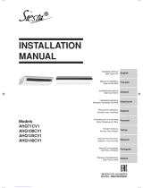
INVERTER CEILING CONCEALED
SPLIT TYPE AIR CONDITIONER
(C Series)
INSTALLATION MANUAL
IM-5CCY-0709(1)-ACSON
Part No.: R08019033602A
IM-5CCY-0709(1)-COVER(EN)-ACSON.1 1IM-5CCY-0709(1)-COVER(EN)-ACSON.1 1 4/8/11 5:16:16 PM4/8/11 5:16:16 PM

IM-5CCY-0709(1)-COVER(EN)-ACSON.2 2IM-5CCY-0709(1)-COVER(EN)-ACSON.2 2 4/8/11 5:16:19 PM4/8/11 5:16:19 PM

English
1-1
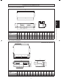
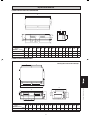
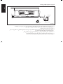
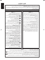
Indoor Unit 5CCY10/15/20/25C/CR
Original Instruction
B
D
C
H
E
A
MN
F
G
O
I
J
K
L
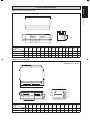
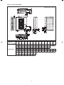
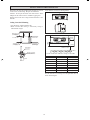
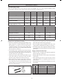
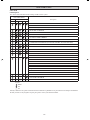
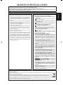
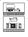
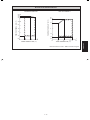
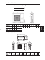
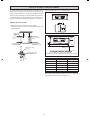
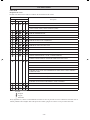
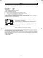
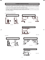
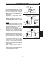
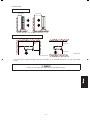
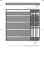
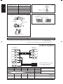
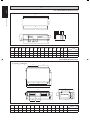
OUTLINE AND DIMENSIONS
Dimension
Model
AB C DEFGHIJKLMN O
5CCY10/15C/CR
31 881 842 802 10 905 72 261 411 351 225 211 232 213 114
5CCY20C/CR
31 1041 1002 962 10 1065 72 261 411 351 225 211 232 213 114
5CCY25C/CR
31 1175 1137 1097 10 1200 72 261 411 351 225 211 232 213 114
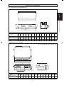
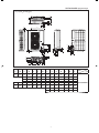
Indoor Unit 5CCY28/38CR
All dimensions are in mm
Dimension
Model
ABCDEFGHI JKLMN
5CCY28CR
372 1001 959 920 410 285 600 339 121 213 54 100 237 216
5CCY38CR
371 1306 1264 1225 563 305 638 401 182 233 207 155 248 241
EE
AAK
B
C
K
D
MN
L
F
I
G
H
J
1 IM 5CCY-0709(1)-EN.indd 11 IM 5CCY-0709(1)-EN.indd 1 4/20/11 3:06:48 PM4/20/11 3:06:48 PM

1-2
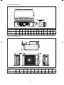
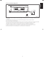
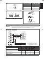
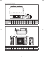
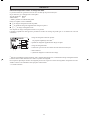
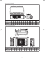
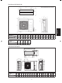
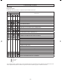
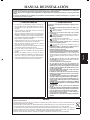
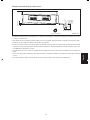
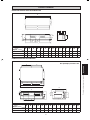
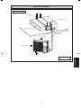
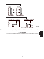
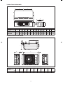
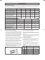
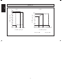
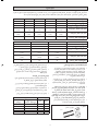
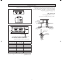
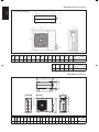
Outdoor Unit 5SLY10/15D/DR
I
G
H
F
K
J
B
C
AB
E
D
E
KK
B
C
D
AA
F
M
N
L
J
G
I
E
Indoor Unit 5CCY50/60CR
Dimension
Model
ABCDEFGHIJKLMN
5CCY50CR
359 1369 1326 1287 593.5 378 541 256 173 306 255.5 160.5 248 220
5CCY60CR
359 1569 1526 1487 693.5 378 541 256 173 306 355.5 160.5 248 220
Dimension
Model
ABCDEFGHI JK
5SLY10/15D/DR
765 12 550 285 8 311 13 29.5 574 105.5 490
H
1 IM 5CCY-0709(1)-EN.indd 21 IM 5CCY-0709(1)-EN.indd 2 4/20/11 3:06:51 PM4/20/11 3:06:51 PM

English
1-3
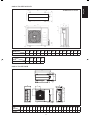
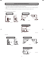
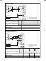
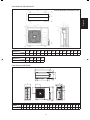
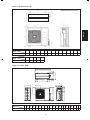
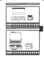
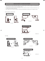
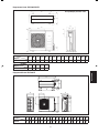
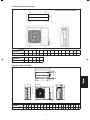
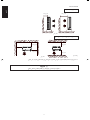
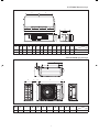
Outdoor Unit 5SLY28CR
A
D
K
E
S
T
S
T
GRR
OMN
H
P
Q
L
C
FU
J
B
I
Dimension
Model
ABCDE FGH I J KLMNO PQR STU
5SLY28CR
940 348 753 855 392 733 603 328 303 370 362 448 190 80 58 180 32 126 32 15 23
B
A
QR
ST
DO
KLL
C
N
P
M
N
FE
C
GH
IJ
All dimensions are in mm
Outdoor Unit 5SLY20/25C/CR
Dimension
Model
ABCDEFGHI JKLMNO
5SLY20/25C/CR
855 730 328 520 182 44 93 149 101 113 603 126 164 17 47
Dimension
Model
PQRST
5SLY20/25C/CR
32 3 237375
1 IM 5CCY-0709(1)-EN.indd 31 IM 5CCY-0709(1)-EN.indd 3 4/20/11 3:06:52 PM4/20/11 3:06:52 PM

1-4
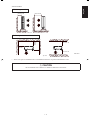
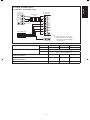
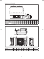
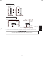
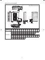
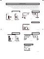
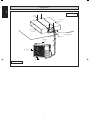
Outdoor Unit 5SLY40/50/60FR
AB AC AD
AE
AFAG
AH
AI
AA
AJ
AK
A
C
B
D
F
E
L
M
KJ
NO
Q
P
R
S
T
U
V
W
Z
X
Y
AT
AS
H
G
AU
AP
AQ
AO
AL
AM
AN
Dimension
Model
ABCDEFGHI JKLMN
5SLY40/50/60FR
900 1374 30 24 60 89 142 89 19 54 95 423 430 95
OPQRSTUVWXYZ
54 19 89 145 84 55 55 223 148 13 52 67
AA AB AC AD AE AF AG AH AI AJ AK AL AM AN
350 140 620 140 30 320 30 59 43 40 94 117 102 70
AO AP AQ AR AS AT AU
45 376 191 70 58 16 16
All dimensions are in mm
AR
I
1 IM 5CCY-0709(1)-EN.indd 41 IM 5CCY-0709(1)-EN.indd 4 4/20/11 3:06:52 PM4/20/11 3:06:52 PM

English
1-5
! WARNING ! CAUTION
Installation and maintenance should be performed by qualifi ed
persons who are familiar with local code and regulation, and
experienced with this type of appliance.
All fi eld wiring must be installed in accordance with the national
wiring regulation.
Ensure that the rated voltage of the unit corresponds to that of
the name plate before commencing wiring work according to
the wiring diagram.
The unit must be GROUNDED to prevent possible hazard due
to insulation failure.
All electrical wiring must not touch the refrigerant piping, or
any moving parts of the fan motors.
Confi rm that the unit has been switched OFF before installing
or servicing the unit.
Disconnect from the main power supply before servicing the
air conditioner unit.
DO NOT pull out the power cord when the power is ON. This
may cause serious electrical shocks which may result in fi re
hazards.
Keep the indoor and outdoor units, power cable and transmission
wiring, at least 1m from TVs and radios, to prevent distorted
pictures and static. {Depending on the type and source of the
electrical waves, static may be heard even when more than
1m away}.
•
•
•
•
•
•
•
•
•
Please take note of the following important points when
installing.
Do not install the unit where leakage of fl ammable gas may
occur.
If gas leaks and accumulates around the unit, it may cause
fi re ignition.
Ensure that drainage piping is connected properly.
If the drainage piping is not connected properly, it may
cause water leakage which will dampen the furniture.
Do not overcharge the unit.
This unit is factory pre-charged.
Overcharge will cause over-current or damage to the
compressor.
Ensure that the unitʼs panel is closed after service or
installation.
Unsecured panels will cause the unit to operate noisily.
Sharp edges and coil surfaces are potential locations which
may cause injury hazards.
Avoid from being in contact with these places.
Before turning off the power supply, set the remote
controllerʼs ON/OFF switch to the “OFF” position to prevent
the nuisance tripping of the unit. If this is not done, the unitʼs
fans will start turning automatically when power resumes, posing
a hazard to service personnel or the user.
Do not operate any heating apparatus too close to the air
conditioner unit. This may cause the plastic panel to melt or
deform as a result of the excessive heat.
Do not install the units at or near doorway.
Do not operate any heating apparatus too close to the air
conditioner unit or use in room where mineral oil, oil vapour
or oil steam exist, this may cause plastic part to melt or
deform as a result of excessive heat or chemical reaction.
When the unit is used in kitchen, keep fl our away from
going
into suction of the unit.
This unit is not suitable for factory used where cutting oil
mist or iron powder exist or voltage fl uctuates greatly.
Do not install the units at area like hot spring or oil refi nery
plant where sulphide gas exists.
Ensure the color of wires of the outdoor unit and the terminal
markings are same to the indoors
respectively.
IMPORTANT: DO NOT INSTALL OR USE THE AIR
CONDITIONER UNIT IN A LAUNDRY ROOM.
Donʼt use joined and twisted wires for incoming power
supply.
Avoid direct contact of any coil treatment cleaners on plastic
part. This may cause plastic part to deform as a result of
chemical reaction.
For any enquiries on spare parts please contact your
authorized dealer.
The equipment is not intended for use in a potentially
explosive atmosphere.
•
•
•
•
•
•
•
•
•
•
•
•
•
•
•
•
•
•
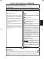
SAFETY PRECAUTIONS
This manual provides the procedures of installation to ensure a safe and good standard of operation for the air conditioner unit.
Special adjustment may be necessary to suit local requirements.
Before using your air conditioner, please read this instruction manual carefully and keep it for future reference.
This appliance is intended to be used by expert or trained users in shops, in light industry and on farms, or for commercial use by lay
persons.
INSTALLATION MANUAL
NOTICE
Disposal requirements
Your air conditioning product is marked with this symbol. This means that electrical and electronic products shall not be mixed with unsorted
household waste.
Do not try to dismantle the system yourself: the dismantling of the air conditioning system, treatment of the refrigerant, of oil and of other
parts must be done by a qualifi ed installer in accordance with relevant local and national legislation.
Air conditioners must be treated at a specialized treatment facility for re-use, recycling and recovery. By ensuring this product is disposed
of correctly, you will help to prevent potential negative consequences for the environment and human health. Please contact the installer or
local authority for more information.
Batteries must be removed from the remote controller and disposed of separately in accordance with relevant local and national legislation.
1 IM 5CCY-0709(1)-EN.indd 51 IM 5CCY-0709(1)-EN.indd 5 4/20/11 3:06:56 PM4/20/11 3:06:56 PM

1-6
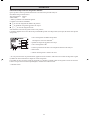
Important information regarding the refrigerant used
This product contains fl uorinated greenhouse gases covered by the Kyoto Protocol.
Do not vent gases into the atmosphere.
Refrigerant type: R410A
GWP
(1)
value: 1975
(1)
GWP = global warming potential
Please fi ll in with indelible ink,
n 1 the factory refrigerant charge of the product,
n 2 the additional refrigerant amount charged in the fi eld and
n 1 + 2 the total refrigerant charge
on the refrigerant charge label supplied with the product.
The fi lled out label must be adhered in the proximity of the product charging port (e.g. onto the inside of the service cover).
1 factory refrigerant charge of the product:
see unit name plate
(2)
2 additional refrigerant amount charged in the fi eld
3 total refrigerant charge
4 contains fl uorinated greenhouse gases covered by the Kyoto Protocol
5 outdoor unit
6 refrigerant cylinder and manifold for charging
(2)
In case of multiple indoor systems, only 1 label must be adhered*, mentioning the total factory refrigerant charge of all
indoor units connected in the refrigerant system.
Periodical inspections for refrigerant leaks may be required depending on European or local legislation. Please contact your
local dealer for more information.
* on the outdoor unit
IMPORTANT
1 IM 5CCY-0709(1)-EN.indd 61 IM 5CCY-0709(1)-EN.indd 6 4/20/11 3:06:56 PM4/20/11 3:06:56 PM

English
1-7
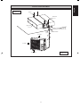
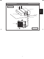
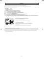
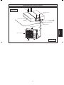
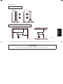
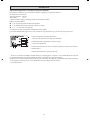
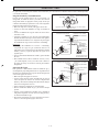
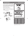
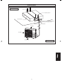
Thermal insulation
Wrap the insulated pipe with the
fi nishing tape from bottom to top
Drain
piping
Supply duct
Return duct
Hanger
INSTALLATION DIAGRAM
Indoor Unit
Outdoor Unit
Air Discharge
Air Intake
Air Intake
1 IM 5CCY-0709(1)-EN.indd 71 IM 5CCY-0709(1)-EN.indd 7 4/20/11 3:06:56 PM4/20/11 3:06:56 PM

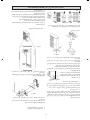
1-8
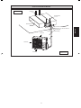
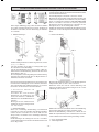
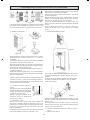
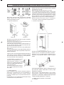
The indoor unit must be installed such that there is no short
circuit of the cool discharge. Respect the installation
clearance. Do not put the indoor unit where there is direct
sunlight on unit. The location is suitable for piping and
drainage and it must have a large distance between a door
and unit.
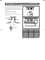
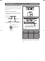
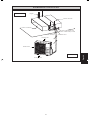
Ceiling Concealed Mounting
• Use the hanger supplied with the unit.
• Make sure that the ceiling is sufficiently strong to
withstand the weight.
Provide clearance for servicing ease and optimal air fl ow as
shown in the diagram.
300mm* or more
300mm
or more
10mm
Field supply
Washer for hanger
bracket (attached)
Tighten
See Detail A
Air inlet side
Aluminium tape
(fi eld supply)
Air outlet side
Aluminium tape
(fi eld supply)
Insulation material
(fi eld supply)
* Can be smaller than 300mm if ceiling is removable.
Detail A
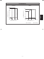
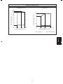
A
L
Center distance of axle (see drawing below)
INSTALLATION OF THE INDOOR UNIT
5CCY A mm (inch) L mm (inch)
10/15C/CR 881 (34.7) 225 (8.9)
20C/CR 1041 (41.0) 225 (8.9)
25C/CR 1176 (46.3) 225 (8.9)
28CR 959 (37.8) 339 (13.3)
38CR 1264 (49.8) 401 (15.8)
50CR 1326 (52.2) 266 (10.5)
60CR 1526 (60.1) 266 (10.5)
A
L
Floor
2300mm or more
Ceiling
1 IM 5CCY-0709(1)-EN.indd 81 IM 5CCY-0709(1)-EN.indd 8 4/20/11 3:06:56 PM4/20/11 3:06:56 PM

English
1-9
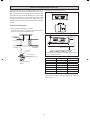
• The drain pipe must be installed as shown in the diagram (see diagram above) to avoid damage caused by leaks and
condensation.
• For the best result, keep the piping as short as possible. Slant the piping at an angle to improve the fl ow.
• Ensure the drain pipe is securely insulated.
• It is necessary to provide a drain trap in the drain outlet to relieve pressure that exists within the unit compared to the outside
atmospheric pressure when the unit is operating. The drain trap is to avoid possibility of splashes or an odor.
• Keep pipes as straight as possible for easy cleaning and to prevent the accumulation of dirt and debris.
• Conduct a water drainage test after the installation is completed. Make sure that the drainage fl ow is smooth.
• In humid environments, use an extra drain pan to cover the entire area of the indoor unit.
Ceiling Concealed Drain Piping Work
Unit : mm
10 mm (0.39")
Slant
Bottom of
the unit
Insulate securely
100
100
Drain
trap
or more
or more
Do not leave in water
1 IM 5CCY-0709(1)-EN.indd 91 IM 5CCY-0709(1)-EN.indd 9 4/20/11 3:06:57 PM4/20/11 3:06:57 PM

1-10
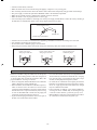
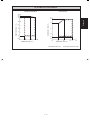
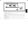
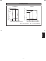
• The outdoor unit must be installed in such a way, so as to prevent short circuit of the hot discharged air or obstruction to
the smooth air fl ow. Please follow the installation clearance shown in the fi gures below. Select the coolest possible place
where intake air temperature is not greater than the outside air temperature.
• Where a wall or other obstacle is in the path of outdoor unitʼs intake or exhaust airfl ow, follow the installation guidelines
below.
• For any of the below installation patterns, the wall height on the exhaust side should be 1200mm or less.
5SLY10/15D/DR and 5SLY20/25C/CR
More than 50 More than 100
Side View
Top View
Top View
More
than 50
More than 50
More than 50
More than 150
More than 100
More than 150
More than 300
Unit: mm
INSTALLATION OF THE OUTDOOR UNIT
More than 100 More than 350
More than 50
More than 50
Top View
Top View
Side View
More
than 100
More than 350
More than 100
More than 350
Unit: mm
5SLY28CR
1200
or less
More than 50
Wall facing one side Wall facing two sides
Wall facing three sides
Wall facing one side Wall facing two sides
Wall facing three sides
1 IM 5CCY-0709(1)-EN.indd 101 IM 5CCY-0709(1)-EN.indd 10 4/20/11 3:06:57 PM4/20/11 3:06:57 PM

English
1-11
Wall facing more than 1 side of obstacle
5SLY40/50/60FR
More than 100 More than 500
More
than 100
More
than
100
More than 100
More than 100
More than 500
• Allow more space for installation above with additional obstacle at top side and installation in series.
Unit: mm
Top View
Side View
Wall facing one side
! CAUTION
• Do not install the unit at altitude over 2000m for both indoor and outdoor.
1 IM 5CCY-0709(1)-EN.indd 111 IM 5CCY-0709(1)-EN.indd 11 4/20/11 3:06:57 PM4/20/11 3:06:57 PM

1-12
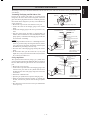
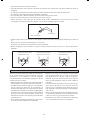
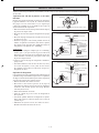
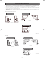
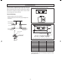
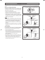
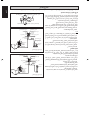
Piping Works And Flaring Technique
Do not use contaminated or damaged copper tubing. If any
piping, evaporator or condenser had been exposed or had
been opened for 15 seconds or more, the system must be
vacuumed. Generally, do not remove plastic, rubber plugs
and brass nuts from the valves, fi ttings, tubings and coils
until it is ready for connection.
If any brazing work is required, ensure that the nitrogen
gas is passed through piping and joints while the brazing
work is being done. This will eliminate soot formation on
the inside walls of the copper tubings.
Cut the pipe stage by stage, advancing the blade of pipe
cutter slowly. Extra force and deep cut will cause more
distortion of pipe and therefore extra burr. See Fig. A
Remove burrs from cut edges of pipes with a remover as
shown in Fig. B. This will avoid unevenness on the fl are
faces which will cause gas leak. Hold the pipe on top
position and burr remover at lower position to prevent metal
chips from entering the pipe.
•
•
•
•
1/4t
Cutting Copper Tube
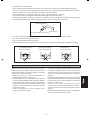
Insert the fl are nuts mounted on the connection parts of both
indoor and outdoor unit, into the copper pipes.
The exact length of pipe protruding from the face of the
swaging block is determined by the fl aring tool. See Fig. C
Fix the pipe fi rmly on the swaging block. Match the centers
of both the fl are die and the fl aring punch, and tighten fl aring
punch fully.
Piping Connection To The Units
Align the center of the piping and suffi ciently tighten the
fl are nut with fi ngers. See Fig. D
Finally, tighten the fl are nut with torque wrench until the
wrench clicks.
When tightening the fl are nut with the torque wrench,
ensure that the direction for tightening follows the arrow
on the wrench.
The refrigerant pipe connection are insulated by closed cell
polyurethane.
•
•
•
•
•
•
•
Copper Tube
Fig. A
Ø Tube, D A (mm)
Inch mm
Imperial
(Wing-nut Type)
Rigid
(Clutch Type)
1/4" 6.35 1.3 0.7
3/8" 9.52 1.6 1.0
1/2" 12.70 1.9 1.3
5/8" 15.88 2.2 1.7
3/4" 19.05 2.5 2.0
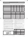
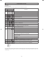
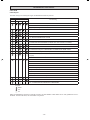
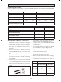
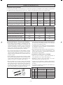
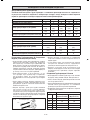
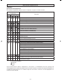
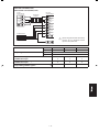
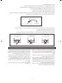
REFRIGERANT PIPING
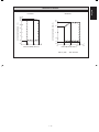
Indoor 5CCY10C/CR 5CCY15C/CR 5CCY20C/CR 5CCY25C/CR 5CCY28CR
Outdoor 5SLY10D/DR 5SLY15D/DR 5SLY20C/CR 5SLY25C/CR 5SLY28CR
Max. allowable length, m 15 15 30 30 50
Max. allowable elevation, m 10 10 10 10 30
Liquid pipe size, mm/(in)
6.35
(1/4")
6.35
(1/4")
6.35
(1/4")
6.35
(1/4")
9.52
(3/8")
Gas pipe size, mm/(in)
9.52
(3/8")
12.70
(1/2")
12.70
(1/2")
15.88
(5/8")
15.88
(5/8")
Additional charge of refrigerant, g/m
(for piping length above 7.5m)
20 20 20 20 50
Indoor 5CCY38CR 5CCY50CR 5CCY60CR
Outdoor 5SLY40FR 5SLY50FR 5SLY60FR
Max. allowable length, m 75 75 75
Max. allowable elevation, m 30 30 30
Liquid pipe size, mm/(in)
9.52
(3/8")
9.52
(3/8")
9.52
(3/8")
Gas pipe size, mm/(in)
15.88
(5/8")
15.88
(5/8")
15.88
(5/8")
Additional charge of refrigerant, g/m
(for piping length above 30m)
50 50 50
Allowable Piping Length
When the pipe length becomes too long, both the capacity and reliability drop. As a result, compressor reliability will be
affected. Always choose the shortest path and follow the recommendation as tabulated below:
1 IM 5CCY-0709(1)-EN.indd 121 IM 5CCY-0709(1)-EN.indd 12 4/20/11 3:06:57 PM4/20/11 3:06:57 PM

English
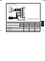
1-13
L
N
SIG
2
1
SIG
2
1
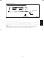
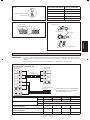
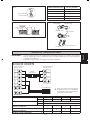
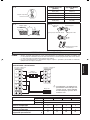
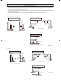
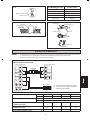
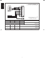
5CCY10/15C/CR - 5SLY10/15D/DR
5CCY20/25C/CR - 5SLY20/25C/CR
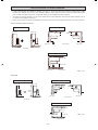
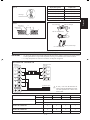
IMPORTANT:
* These values are for information only, they should be checked and selected to comply with the local and/or national
codes and regulations. They are also subjected to the type of installation and size of conductors.
** The appropriate voltage range should be checked with data label on the unit.
Power Supply Cable
Outdoor Unit
Terminal Block
Interconnection
cable
ELECTRICAL WIRING CONNECTION
Model Indoor 5CCY10C/CR 5CCY15C/CR 5CCY20C/CR 5CCY25C/CR
Outdoor 5SLY10D/DR 5SLY15D/DR 5SLY20C/CR 5SLY25C/CR
Voltage range** Indoor
220V – 240V/1Ph/50Hz + !
Outdoor
220V – 240V/1Ph/50Hz + !
Power supply cable size* mm
2
Number of conductors
1.5
3
1.5
3
1.5
3
2.5
3
Interconnection cable size* mm
2
Number of conductors
1.5
4
1.5
4
1.5
4
2.5
4
Recommended time delay fuse* A 15 15 20 20
Copper Tube
Swaging Block
Fig. B
Remove Burr
Fig. C
Fig. D
Flared Tube
Flare Joint
Flare Nut
Indoor Piping
Torque Wrench
Spanar
Pipe Size, mm (in) Torque, Nm / (ft-lb)
6.35 (1/4") 18 (13.3)
9.52 (3/8") 42 (31.0)
12.70 (1/2") 55 (40.6)
15.88 (5/8") 65 (48.0)
19.05 (3/4") 78 (57.6)
D
A
There must be an all pole
disconnection in the supply
mains with a contact separation
of at least 3mm.
!
Indoor Unit
Terminal Block
1 IM 5CCY-0709(1)-EN.indd 131 IM 5CCY-0709(1)-EN.indd 13 4/20/11 3:06:58 PM4/20/11 3:06:58 PM

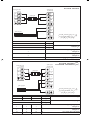
1-14
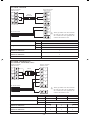
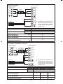
3
2
1
2
1
3
L
N
SIG
N
L
SIG
N
L
N
L
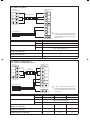
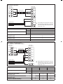
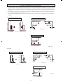
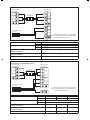
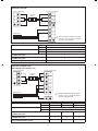
5CCY38CR - 5SLY40FR (1 Phase)
5CCY50/60CR - 5SLY50/60FR (1 Phase)
Power Supply Cable
Indoor Unit
Terminal Block
Model Indoor 5CCY38CR 5CCY50CR 5CCY60CR
Outdoor 5SLY40FR 5SLY50FR 5SLY60FR
Voltage range** Indoor
220V – 240V/1Ph/50Hz + !
Outdoor
220V – 240V/1Ph/50Hz + !
Power supply cable size* mm
2
Number of conductors
6
3
6
3
6
3
Interconnection cable size* mm
2
Number of conductors
1.5
4
1.5
4
1.5
4
Recommended time delay fuse* A 32 32 32
5CCY28CR - 5SLY28CR
Indoor Unit
Terminal Block
Interconnection
cable
Model Indoor 5CCY28CR
Outdoor 5SLY28CR
Voltage range** Indoor
220V – 240V/1Ph/50Hz + !
Outdoor
220V – 240V/1Ph/50Hz + !
Power supply cable size* mm
2
Number of conductors
2.5
3
Interconnection cable size* mm
2
Number of conductors
1.5
4
Recommended time delay fuse* A 25
Power Supply Cable
Outdoor Unit
Terminal Block
Interconnection
cable
Outdoor Unit
Terminal Block
There must be an all pole
disconnection in the supply
mains with a contact separation
of at least 3mm.
!
There must be an all pole
disconnection in the supply
mains with a contact separation
of at least 3mm.
!
1 IM 5CCY-0709(1)-EN.indd 141 IM 5CCY-0709(1)-EN.indd 14 4/20/11 3:06:58 PM4/20/11 3:06:58 PM

English
1-15
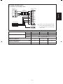
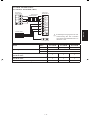
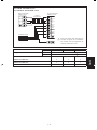
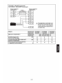
3
2
1
3
2
1
L1
L2
L3
N
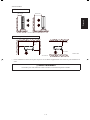
5CCY38CR - 5SLY40FR (3 Phase)
5CCY50/60CR - 5SLY50/60FR (3 Phase)
Model Indoor 5CCY38CR 5CCY50CR 5CCY60CR
Outdoor 5SLY40FR 5SLY50FR 5SLY60FR
Voltage range** Indoor
220V - 240V/1Ph/50Hz +
!
Outdoor
380V - 415V/3N~/50Hz +
!
Power supply cable size* mm
2
Number of conductors
4
5
4
5
4
5
Interconnection cable size* mm
2
Number of conductors
1.5
4
1.5
4
1.5
4
Recommended time delay fuse* A 20 20 20
Power Supply Cable
Indoor Unit
Terminal Block
Interconnection
Cable
Outdoor Unit
Terminal Block
There must be an all pole
disconnection in the supply
mains with a contact separation
of at least 3mm.
!
1 IM 5CCY-0709(1)-EN.indd 151 IM 5CCY-0709(1)-EN.indd 15 4/20/11 3:06:59 PM4/20/11 3:06:59 PM

1-16
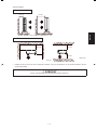
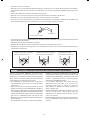
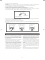
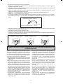
SPECIAL PRECAUTIONS WHEN DEALING WITH R410A UNIT
Attach insulation sleeve
Round crimp-style terminal
Electric wire
• All wires must be fi rmly connected.
• Make sure all the wire do not touch the refrigerant pipings, compressor or any moving parts.
• The connecting wire between the indoor unit and the outdoor unit must be clamped by using provided cord anchorage.
• The power supply cord must be equivalent to H07RN-F which is the minimum requirement.
• Make sure no external pressure is applied to the terminal connectors and wires.
• Make sure all the covers are properly fi xed to avoid any gap.
• Use round crimp-style terminal for connecting wires to the power supply terminal block. Connect the wires by matching to
the indication on terminal block. (Refer to the wiring diagram attached on the unit).
Connect wires of the
same gauge to both side.
Do not connect wires of the
same gauge to one side.
Do not connect wires
of different gauges.
R410A is a new HFC refrigerant which does not damage the
ozone layer. The working pressure of this new refrigerant is
1.6 times higher than conventional refrigerant (R22), thus
proper installation / servicing is essential.
• Never use refrigerant other than R410A in an air conditioner
which is designed to operate with R410A.
• POE or PVE oil is used as lubricant for R410A compressor,
which is different from the mineral oil used for R22
compressor. During installation or servicing, extra precaution
must be taken not to expose the R410A system too long
to moist air. Residual POE or PVE oil in the piping and
components can absorb moisture from the air.
• To prevent mischarging, the diameter of the service port on
the fl are valve is different from that of R22.
• Use tools and materials exclusively for refrigerant R410A.
Tools exclusively for R410A are manifold valve, charging
hose, pressure gauge, gas leak detector, fl are tools, torque
wrench, vacuum pump and refrigerant cylinder.
• As an R410A air conditioner incurs higher pressure than
R22 units, it is essential to choose the copper pipes correctly.
Never use copper pipes thinner than 0.8mm even though
they are available in the market.
• If the refrigerant gas leakage occurs during installation /
servicing, be sure to ventilate fully. If the refrigerant gas
comes into contact with fi re, a poisonous gas may occur.
• When installing or removing an air conditioner, do not allow
air or moisture to remain in the refrigerant cycle.
• Used the correct screwdriver for terminal screws tightening. Unsuitable screwdrivers can damage the screw head.
• Over tightening can damage the terminal screws.
• Do not connect wire of different gauge to same terminal.
• Keep wiring in an orderly manner. Prevent the wiring from obstructing other parts and the terminal box cover.
1 IM 5CCY-0709(1)-EN.indd 161 IM 5CCY-0709(1)-EN.indd 16 4/20/11 3:06:59 PM4/20/11 3:06:59 PM

English
1-17
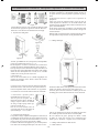
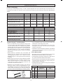
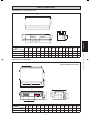
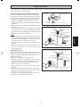
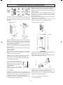
VACUUMING AND CHARGING
Vacuuming is necessary to eliminate all moisture and air from the system. The series II Outdoor Unit is provided with fl are
valve fi ttings.
Vacuuming The Piping And The Indoor Unit
Except for the outdoor unit which is pre-charged with
refrigerant, the indoor unit and the refrigerant connection
pipes must be air-purged because the air containing moisture
that remains in the refrigerant cycle may cause malfunction
of the compressor.
• Remove the caps from the valve and the service port.
• Connect the center of the charging gauge to the vacuum
pump.
• Connect the charging gauge to the service port of the 3-way
valve.
• Start the vacuum pump. Evacuate for approximately 30
minutes. The evacuation time varies with different vacuum
pump capacity. Confi rm that the charging gauge needle has
moved towards -760mmHg.
Caution
• If the gauge needle does not move to -760mmHg, be sure to
check for gas leaks (using the refrigerant detector) at fl are
type connection of the indoor and outdoor unit and repair
the leak before proceeding to the next step.
• Close the valve of the changing gauge and stop the vacuum
pump.
• On the outdoor unit, open the suction valve (3 way) and
liquid valve (2 way) (in anti-clockwise direction) with 4mm
key for hexagon sacked screw.
Charge Operation
This operation must be done by using a gas cylinder and a
precise weighing machine. The additional charge is topped-up
into the outdoor unit using the suction valve via the service
port.
• Remove the service port cap.
• Connect the low pressure side of the charging gauge to the
suction service port center of the cylinder tank and close
the high pressure side of the gauge. Purge the air from the
service hose.
• Start the air conditioner unit.
• Open the gas cylinder and low pressure charging valve.
• When the required refrigerant quantity is pumped into
the unit, close the low pressure side and the gas cylinder
valve.
• Disconnect the service hose from service port. Put back the
service port cap.
Refrigerant Piping
Outdoor Unit 3 ways valve
Allen key
Service Port
Flare nut
HIGH PRESSURE GAUGE
GAUGE MANIFOLD
LOW PRESSURE GAUGE
HANDLE HI (ALWAYS CLOSED)
CHARGE HOSE
-760mmHg
HANDLE LO
CHARGE HOSE
VACUUM PUMP
ADAPTER FOR
COUNTER FLOW
PREVENTION
CHECK VALVE
LIQUID VALVE
HIGH PRESSURE GAUGE
LOW PRESSURE GAUGE
GAUGE MANIFOLD
-760mmHg
HANDLE LO
HANDLE HI (ALWAYS CLOSED)
CHARGE HOSE
CHARGE HOSE
CHECK VALVE
LIQUID VALVE
GAS VALVE
(3-WAY)
CONFIGURATION OF AIR
PURGE BY CHARGING
CONFIGURATION OF AIR
PURGE BY CHARGING
GAS VALVE
(3-WAY)
1 IM 5CCY-0709(1)-EN.indd 171 IM 5CCY-0709(1)-EN.indd 17 4/20/11 3:06:59 PM4/20/11 3:06:59 PM

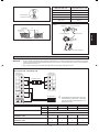
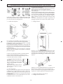
1-18
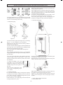
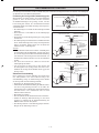
As shown in fi gure above, it is recommended to move the unit
by grabbing the left and right grip. Place your hands on the
corner to avoid deforming of the casing.
Figure 1
A total of 4 direction options (refer fi gure 2a) for connecting
pipe (w, x, y, z) are available for your convenience.
Cutting out the 2 slits with a metal saw make it possible to
install as shown in fi gures 2a.
In order to make the connecting pipe in a downward direction
(refer fi gure 2b), make a knockout hole by drilling through
the center area around the knockout hole.
It is recommended to use a Ø6mm drill for this process
(refer fi gure 2c).
After completing the knockout process, it is recommended
to apply repair paint to the edge and surrounding surfaces to
prevent rusting.
1. Handling
2. Refrigerant piping
Cover the pipe through-holes with insulation material to
conceal all gaps to prevent small animals or insects from
entering the outdoor unit which may result short circuit in
the control box.
4. Charging refrigerant
For cases where complete recharge of refrigerant is required,
vacuuming via service part is mandatory, do not use stop valve
port in this case because vacuuming through this stop valve
port can not be executed completely.
Outdoor units have 1 port on the piping. It is between the heat
exchanger and the 4-way valve.
5. Pump-down operation
Never by-pass the low pressure switch or low pressure sensor
during pump down operation.
Power supply must be cut off before pump-down operation.
After opening the front panel, cover the PCB and terminal
board with insulation sheet to avoid electric shock by
accidental touching of LIVE parts.
Do not leave the unit unattended if the front panel is open.
Close the front panel before leaving the outdoor unit.
Turn on the power supply and carry out pumping-down
operation according to the steps written at front panel.
6. Electrical wiring work
Figure 4
Secure the ground wire to the stop valve attachment plate
(refer fi gure 4) so that it does not slide.
Ensure the front cover does not rise up after the wiring work
is down. Close the front cover securely.
Z
Y
X
W
Figure 2a
Figure 2b
Figure 2c
3. Caution for handling service port
To be able to recover all remaining
refrigerant at charge hose, always use
a fl exible charge hose with a push-rod
and valve.
After the work, tighten the valve
cover in place with tightening torque:
11.5~13.9N.m
Figure 3
BELOW INFORMATION IS APPLICABLE FOR 5SLY40/50/60FR ONLY
1
2
1
2
Figure 5
When cables are routed from the unit, a protection sleeve for
the conduits can be inserted at the knock-out hole.
It there is no wire conduit, do protect the wires with vinyl
tubes to prevent cutting the wires by sharp edges of knock-
out hole.
1 Power supply wiring and earth wire
2 Interconnection wire
1 IM 5CCY-0709(1)-EN.indd 181 IM 5CCY-0709(1)-EN.indd 18 4/20/11 3:07:00 PM4/20/11 3:07:00 PM
Sayfa yükleniyor...
Sayfa yükleniyor...
Sayfa yükleniyor...
Sayfa yükleniyor...
Sayfa yükleniyor...
Sayfa yükleniyor...
Sayfa yükleniyor...
Sayfa yükleniyor...
Sayfa yükleniyor...
Sayfa yükleniyor...
Sayfa yükleniyor...
Sayfa yükleniyor...
Sayfa yükleniyor...
Sayfa yükleniyor...
Sayfa yükleniyor...
Sayfa yükleniyor...
Sayfa yükleniyor...
Sayfa yükleniyor...
Sayfa yükleniyor...
Sayfa yükleniyor...
Sayfa yükleniyor...
Sayfa yükleniyor...
Sayfa yükleniyor...
Sayfa yükleniyor...
Sayfa yükleniyor...
Sayfa yükleniyor...
Sayfa yükleniyor...
Sayfa yükleniyor...
Sayfa yükleniyor...
Sayfa yükleniyor...
Sayfa yükleniyor...
Sayfa yükleniyor...
Sayfa yükleniyor...
Sayfa yükleniyor...
Sayfa yükleniyor...
Sayfa yükleniyor...
Sayfa yükleniyor...
Sayfa yükleniyor...
Sayfa yükleniyor...
Sayfa yükleniyor...
Sayfa yükleniyor...
Sayfa yükleniyor...
Sayfa yükleniyor...
Sayfa yükleniyor...
Sayfa yükleniyor...
Sayfa yükleniyor...
Sayfa yükleniyor...
Sayfa yükleniyor...
Sayfa yükleniyor...
Sayfa yükleniyor...
Sayfa yükleniyor...
Sayfa yükleniyor...
Sayfa yükleniyor...
Sayfa yükleniyor...
Sayfa yükleniyor...
Sayfa yükleniyor...
Sayfa yükleniyor...
Sayfa yükleniyor...
Sayfa yükleniyor...
Sayfa yükleniyor...
Sayfa yükleniyor...
Sayfa yükleniyor...
Sayfa yükleniyor...
Sayfa yükleniyor...
Sayfa yükleniyor...
Sayfa yükleniyor...
Sayfa yükleniyor...
Sayfa yükleniyor...
Sayfa yükleniyor...
Sayfa yükleniyor...
Sayfa yükleniyor...
Sayfa yükleniyor...
Sayfa yükleniyor...
Sayfa yükleniyor...
Sayfa yükleniyor...
Sayfa yükleniyor...
Sayfa yükleniyor...
Sayfa yükleniyor...
Sayfa yükleniyor...
Sayfa yükleniyor...
Sayfa yükleniyor...
Sayfa yükleniyor...
Sayfa yükleniyor...
Sayfa yükleniyor...
Sayfa yükleniyor...
Sayfa yükleniyor...
Sayfa yükleniyor...
Sayfa yükleniyor...
Sayfa yükleniyor...
Sayfa yükleniyor...
Sayfa yükleniyor...
Sayfa yükleniyor...
Sayfa yükleniyor...
Sayfa yükleniyor...
Sayfa yükleniyor...
Sayfa yükleniyor...
Sayfa yükleniyor...
Sayfa yükleniyor...
Sayfa yükleniyor...
Sayfa yükleniyor...
Sayfa yükleniyor...
Sayfa yükleniyor...
Sayfa yükleniyor...
Sayfa yükleniyor...
Sayfa yükleniyor...
Sayfa yükleniyor...
Sayfa yükleniyor...
Sayfa yükleniyor...
Sayfa yükleniyor...
Sayfa yükleniyor...
Sayfa yükleniyor...
Sayfa yükleniyor...
Sayfa yükleniyor...
Sayfa yükleniyor...
Sayfa yükleniyor...
Sayfa yükleniyor...
Sayfa yükleniyor...
Sayfa yükleniyor...
Sayfa yükleniyor...
Sayfa yükleniyor...
Sayfa yükleniyor...
Sayfa yükleniyor...
Sayfa yükleniyor...
Sayfa yükleniyor...
Sayfa yükleniyor...
Sayfa yükleniyor...
Sayfa yükleniyor...
Sayfa yükleniyor...
Sayfa yükleniyor...
Sayfa yükleniyor...
Sayfa yükleniyor...
Sayfa yükleniyor...
Sayfa yükleniyor...
Sayfa yükleniyor...
Sayfa yükleniyor...
Sayfa yükleniyor...
Sayfa yükleniyor...
Sayfa yükleniyor...
Sayfa yükleniyor...
Sayfa yükleniyor...
Sayfa yükleniyor...
Sayfa yükleniyor...
Sayfa yükleniyor...
Sayfa yükleniyor...
Sayfa yükleniyor...
Sayfa yükleniyor...
Sayfa yükleniyor...
Sayfa yükleniyor...
Sayfa yükleniyor...
Sayfa yükleniyor...
Sayfa yükleniyor...
Sayfa yükleniyor...
Sayfa yükleniyor...
Sayfa yükleniyor...
Sayfa yükleniyor...
Sayfa yükleniyor...
-
 1
1
-
 2
2
-
 3
3
-
 4
4
-
 5
5
-
 6
6
-
 7
7
-
 8
8
-
 9
9
-
 10
10
-
 11
11
-
 12
12
-
 13
13
-
 14
14
-
 15
15
-
 16
16
-
 17
17
-
 18
18
-
 19
19
-
 20
20
-
 21
21
-
 22
22
-
 23
23
-
 24
24
-
 25
25
-
 26
26
-
 27
27
-
 28
28
-
 29
29
-
 30
30
-
 31
31
-
 32
32
-
 33
33
-
 34
34
-
 35
35
-
 36
36
-
 37
37
-
 38
38
-
 39
39
-
 40
40
-
 41
41
-
 42
42
-
 43
43
-
 44
44
-
 45
45
-
 46
46
-
 47
47
-
 48
48
-
 49
49
-
 50
50
-
 51
51
-
 52
52
-
 53
53
-
 54
54
-
 55
55
-
 56
56
-
 57
57
-
 58
58
-
 59
59
-
 60
60
-
 61
61
-
 62
62
-
 63
63
-
 64
64
-
 65
65
-
 66
66
-
 67
67
-
 68
68
-
 69
69
-
 70
70
-
 71
71
-
 72
72
-
 73
73
-
 74
74
-
 75
75
-
 76
76
-
 77
77
-
 78
78
-
 79
79
-
 80
80
-
 81
81
-
 82
82
-
 83
83
-
 84
84
-
 85
85
-
 86
86
-
 87
87
-
 88
88
-
 89
89
-
 90
90
-
 91
91
-
 92
92
-
 93
93
-
 94
94
-
 95
95
-
 96
96
-
 97
97
-
 98
98
-
 99
99
-
 100
100
-
 101
101
-
 102
102
-
 103
103
-
 104
104
-
 105
105
-
 106
106
-
 107
107
-
 108
108
-
 109
109
-
 110
110
-
 111
111
-
 112
112
-
 113
113
-
 114
114
-
 115
115
-
 116
116
-
 117
117
-
 118
118
-
 119
119
-
 120
120
-
 121
121
-
 122
122
-
 123
123
-
 124
124
-
 125
125
-
 126
126
-
 127
127
-
 128
128
-
 129
129
-
 130
130
-
 131
131
-
 132
132
-
 133
133
-
 134
134
-
 135
135
-
 136
136
-
 137
137
-
 138
138
-
 139
139
-
 140
140
-
 141
141
-
 142
142
-
 143
143
-
 144
144
-
 145
145
-
 146
146
-
 147
147
-
 148
148
-
 149
149
-
 150
150
-
 151
151
-
 152
152
-
 153
153
-
 154
154
-
 155
155
-
 156
156
-
 157
157
-
 158
158
-
 159
159
-
 160
160
-
 161
161
-
 162
162
-
 163
163
-
 164
164
-
 165
165
-
 166
166
-
 167
167
-
 168
168
-
 169
169
-
 170
170
-
 171
171
-
 172
172
-
 173
173
-
 174
174
-
 175
175
-
 176
176


Acson 5CCY10C/CR Yükleme Rehberi
- Kategori
- Split sistem klimalar
- Tip
- Yükleme Rehberi
diğer dillerde
- español: Acson 5CCY10C/CR Guía de instalación
- français: Acson 5CCY10C/CR Guide d'installation
- italiano: Acson 5CCY10C/CR Guida d'installazione
- Deutsch: Acson 5CCY10C/CR Installationsanleitung
- English: Acson 5CCY10C/CR Installation guide
- русский: Acson 5CCY10C/CR Инструкция по установке
İlgili makaleler
Diğer belgeler
-
Mitsubishi MSZ-HJ35VA El kitabı
-
McQuay E Series Yükleme Rehberi
-
 Siesta AHQ125CV1 Yükleme Rehberi
-
Sharp AE-A9NR Kullanma talimatları
-
Carrier 38VBH...S Yükleme Rehberi
-
-
-
LG AMNW07GDBR0 Yükleme Rehberi
-
Mitsubishi Electric PXZ-4F75VG Split-Type Air-Conditioner Kullanım kılavuzu
-
