Murray 866079-00 Kullanım kılavuzu
- Kategori
- Çim biçme makinaları
- Tip
- Kullanım kılavuzu

Not for
Reproduction
Model No.
866079-00
866081-00
866083-00
866084-00
866085-00
866086-00
866087-00
80015485
Rev. -
Operator’s Manual
Manual del operador
Manuel utilisateur
Manual do Operador
Mwongozo wa Mwendeshaji
Kullanım Kılavuzu
Walk Behind Mowers
Cortacésped de empuje manual
Tondeuses poussées
Cortador de grama
Tembea Nyuma Ya Mashine Ya
Kukata Nyasi
Yaya Kumandalı Çim Biçme Makinesi
!
en - English
ar -
es - Español
fr - Français
pt - Português
sw - Kiswahili
tr - Türkçe

Not for
Reproduction
Thank You for purchasing this quality-built Murray™ mower. We’re pleased that you placed your confidence in the Murray
brand. When operated and maintained according to the instructions in this manual, your Murray mower will provide many years
of dependable service.
This manual contains safety information to make you aware of the hazards and risks associated with the machine and how
to avoid them. This machine is designed and intended only for finish cutting of established lawns and is not intended for any
other purpose. It is important that you read and understand these instructions thoroughly before attempting to start or operate
this equipment. Save these original instructions for future
reference.
Date of Purchase___________________________________________________________________________
Retailer___________________________________________________________________________________
Retailer’s Phone Number_____________________________________________________________________
Equipment
Model Number_______________________________________________________________________
Serial Number_______________________________________________________________________
Engine
Model________________________Type_______________________Code______________________
Copyright © 2015 Briggs & Stratton Power Products Group, LLC.
Milwaukee, WI, USA. All rights reserved.
MURRAY is a trademark of
Briggs & Stratton Power Products Group, LLC.
2 www.murray.com

Not for
Reproduction
3
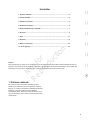
Table of Contents
1. Intended use ............................................................................................................... 3
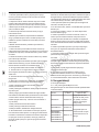
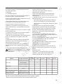
2. Technical specifications ...........................................................................................4
3. Features and controls ..............................................................................................4
4. Symbols and warnings .............................................................................................. 6
5. Instructions for safe operation ................................................................................. 7
6. Assembly ...................................................................................................................8
7. Adjustment ..............................................................................................................11
8. Operation ..................................................................................................................12
9. Maintenance and storage ......................................................................................14
10. Troubleshooting ..................................................................................................... 16
Important
For your own safety, please read the instructions in this manual and the operator’s manual for the engine fully before assem-
bling and operating. Failure to follow instructions can result in serious personal injuries. Spend a few moments to familiarize
yourself with your mower before each use.
1. Intended use
This lawn mower has been designed for cutting grass on
lawn areas and intended for private use i.e. for use in home
and gardening environments. The lawnmower is to be used
only for its prescribed purpose. Any other use is deemed to
be a case of misuse which may cause damage and injuries.

Not for
Reproduction
4 www.murray.com
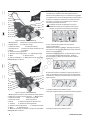
WARNING: The side discharge deflector MUST be
manually installed before first starting and any subsequent
operation of this lawnmower.
!
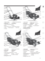
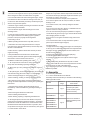
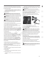
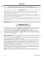
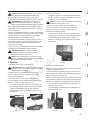
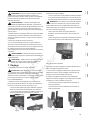
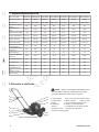
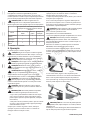
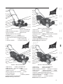
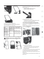
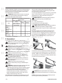
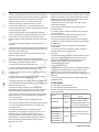
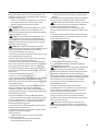
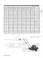
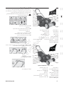
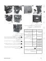
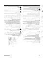
3. Features and controls
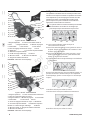
1. Upper handle 2. Engine stop control lever
3. Lower handle 4. Handle knob 5. Rope guide
6. Wheel 7. Cutting height adjustment lever
11. Spark plug boot 12. Oil cap
13. Fuel cap 14. Starter rope handle
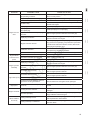
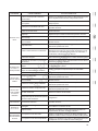
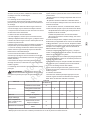
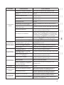
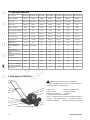
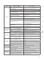
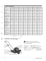
Model Name MP450D20 MP625MD21H MP550RM21 MP675RM21H MP550RMD21 MP675RMD21H MX675RMD22H
Model Number 866079 866081 866083 866084 866085 866086 866087
Engine type B&S 450E B&S 625EX B&S 550EX B&S 675EXI B&S 550EX B&S 675EXI B&S 675EXI
Self Propelled Drive No No No No No No Yes
Engine Displacement 125cc 150cc 140cc 163cc 140cc 163cc 163cc
Nominal Power(KW) 1.66 2.31 2.04 2.49 2.04 2.49 2.49
Deck Width 510mm 530mm 530mm 530mm 530mm 530mm 560mm
Blade Width 500mm 510mm 510mm 510mm 510mm 510mm 530mm
Rated Speed 3100rpm 3100rpm 3100rpm 3100rpm 3100rpm 3100rpm 3100rpm
Fuel Tank
Capacity(Liter)
0.76 0.76 0.76 1.03 0.76 1.03 1.03
Grass catcher
capacity(Liter)
N/A N/A 60 60 60 60 60
Net Weight(kg) 19 29 27 31 28 32 35
Height adjustment
range(cm)
25-66 25-76 25-76 25-76 25-76 25-76 30-85
Rear Bagging No No Yes Yes Yes Yes Yes
Side Discharging No No Yes Yes Yes Yes Yes
Mulching No Yes Yes Yes Yes Yes Yes
Oil capacity(ml) 473 473 473 473 473 473 473
Vibration on Upper
Handle(m/s2)
4.83 2.47 3.89 3.26 3.16 5.3 3.26
2. Technical specifications
Figure 1. Model: MP450D20
1
2
3
5
4
6
7
12
10
8
9
11
13
14

Not for
Reproduction
5
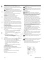
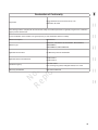
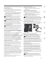
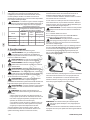
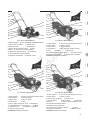
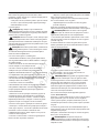
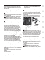
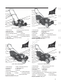
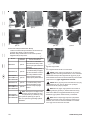
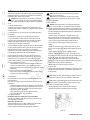
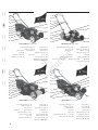
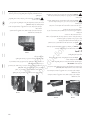
Fig 2. Model: MP625MD21H
1
2
5
4
6
7
12
8
10
1. Upper handle 2. Engine stop control lever
3. Starter rope handle 4. Rope guide
5. Handle knob 6. Lower handle
7. Cutting height adjustment lever
8. Wheel 9. Engine
12. Deck 13. Spark plug boot 14. Fuel cap
15. Oil cap
11
3
14
13
15
9
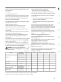
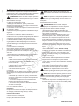
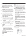
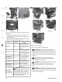
Fig 3. Model: MP550RM21
1. Upper handle 2. Engine stop control lever
3. Lower handle 4. Handle Knob
5. Rope guide 6. Grass bag
7. Rear door 8. Wheel
9. Cutting height adjustment lever 10. Deck
11. Spark plug boot 12. Engine 13. Oil cap
14. Fuel cap 15. Starter rope handle
Including A: Mulch plug
A
1
12
11
13
2
3
4
5
6
8
9
7
10
15
14
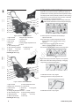
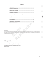
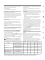
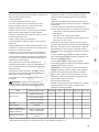
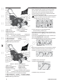
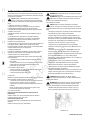
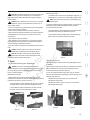
Fig 4. Model: MP675RM21H
1. Upper handle 2. Engine stop control lever
3. Lower handle 4. Handle Knob
5. Rope guide 6. Grass bag 7. Rear door
8. Cutting height adjustment lever 9.Wheel
10. Engine 11. Deck 12. Spark plug boot
13. Oil cap 14. Fuel cap
15. Starter rope handle
Including A: Mulch plug
3
12
14
1
2
4
5
6
8
9
11
7
13
15
10
A
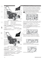
Fig 5. Model: MP550RMD21
1. Upper handle 2. Engine stop control lever
3. Lower handle 4. Handle Knob
5. Starter rope handle 6. Rope guide
7. Grass bag 8. Rear door 9. Deck
10. Wheel 11. Cutting height adjustment lever
14. Spark plug boot 15. Engine
16. Fuel cap 17. Oil cap
Including A: Mulch plug
3
14
17
1
2
4
5
6
7
8
9
11
12
13
10
15
16
A

Not for
Reproduction
6 www.murray.com
1
2
3
5
4
6
9
14
13
12
17
16
15
8
7
11
10
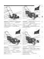
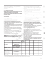
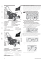
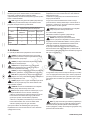
1. Upper handle 2. Engine stop control lever
3. Lower handle 4. Handle Knob
5. Rope guide 6. Grass bag
7. Rear door 8. Cutting height adjustment lever
9. Wheel 10. Deck
11. Side discharge cover
14. Engine 15. Oil cap 16. Fuel cap
17. Starter rope handle
Including A: Mulch plug
Figure 6. Model: MP675RMD21H
A
1
2
4
6
5
7
9
15
14
11
18
17
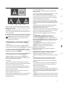
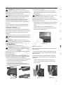
1. Upper handle 2. Self-propelled drive lever
3. Engine stop control lever 4. Lower handle
5. Handle Knob 6. Grass bag 7. Rope guide
8. Rear door 9. Wheel
10. Cutting height adjustment lever 11. Deck
14. Spark plug boot 15. Engine 16. Oil cap
17. Starter rope handle 18. Fuel cap
Including A: Mulch plug
Figure 7. Model: MX675RMD22H
8
12
13
16
3
10
A
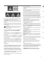
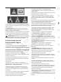
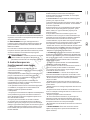
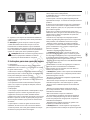
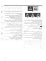
4. Symbols and warnings
Symbols are used in this manual to attract your attention to
possible risks. The safety symbols and the explications which
accompany them must be perfectly understood. The warning
themselves do not avoid the risks and cannot be a substitute
for proper methods of avoiding accidents.
The safety alert symbol is used to identify safety infor-
mation about hazards that can result in personal injury.
A1 Read operator’s manual before attempting to
operate the mower.
A2 To avoid injury or death, keep hands and feet
away from the mower deck at all times during
operation.
A3 To avoid injury to others, do not mow when
Others, especially children, are around.
A4
Disconnect spark plug boot before performing repair.
B1 To avoid injury from thrown objects, do not operate
the mower unless all mulching, discharge, or bagging
components are in their proper place.
C1 Release the lever to stop engine.
C2 Engage the lever for self-propelled drive.
D1 Release the lever to stop engine.
!
A1 A2 A3 A4
B1
C1 C2
D1

Not for
Reproduction
7
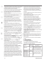
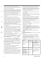
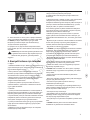
E1
F1 F2 F3
F1
Fire or explosion can cause severe burns or death.
F2 WARNING! The lawnmower exhaust gas contains toxic
substances. Do not run the engine in closed or poorly venti-
lated areas.
F3 Running engines produce heat. Engine parts, especially
occur on contact.
!
WARNING! Keep the safety signs clear and visible on
the equipment. Replace the safety signs if they are
missing or illegible.
5.
Instructions for safe operation
5.1 Training
1. Read the instructions carefully. Be thoroughly familiar with
the controls and the proper use of the walk-behind mower
before starting.
2. Never allow children or people unfamiliar with these instruc-
tions to use the lawnmower. Local regulations can restrict the
age of the operator.
3.Keep in mind that the operator or user is responsible for ac-
cidents or hazards occurring to other people or their property.
4.The operators must receive proper training in the use, ad-
justment and operation of the machine, including prohibited
operations.
5.2 Preparation
1. Always wear substantial and slip-resistant footwear and
long trousers when operating the lawnmower. Do not operate
the equipment when barefoot or wearing open sandals.
2. Always wear safety goggles or safety glasses with side
shields when operating the lawnmower to protect your eyes
from foreign objects which can be thrown from the lawmower.
3. Only operate the lawnmower when there is a good visibility,
4. Where feasible, avoid mowing in wet grass. Reduced fooing
could cause slipping.
5. Do not mow in inclement weather such as rain, strong
winds, or thunderstorms.
6. WARNING! Do not use the lawnmower when there is a risk
of lightning.
7. Never operate the lawnmower while people - especially
children - or pets are nearby.
8. Thoroughly inspect the area where the equipment is to be
used and remove all foreign objects such as stones, toys,
sticks, wires, etc. which can be thrown by the lawnmower.
alcohol, drugs or other medication which can cause drowsi-
10. Before using, always do visual inspection of the lawnmow-
er to ensure that all components are present, undamaged and
- Check the condition of the blade, blade bolt and cutter
assembly. Replace worn or damaged blades and bolts as
complete sets to preserve balance.
11. CAUTION! Never operate the lawnmower with defective
guards. Never operate the lawnmower without safety devices
such as the entire rear door, the entire side discharge cover,
in place:
installed prior to use.
12. The lawnmower safety systems or features shall not be
tampered with or disabled.
-
per with the engine speed.
14.WARNING!
and explosive. Fire or explosion can cause severe burns or
death:
- Never remove the cap of the fuel tank or add fuel while the
engine is running or when the engine is hot.
- Fill or drain fuel only in a well-ventilated area.
stored.
- If fuel is spilled, do not attempt to start the engine but move
the machine away from the area of spillage and avoid creating
any source of ignition until petrol vapors have dissipated.
- Replace all fuel tank and container caps securely.
15.WARNING! Avoid skin to have repeated or prolonged
contact gasoline and avoid inhalation of gasoline vapor.

Not for
Reproduction
8 www.murray.com
5.3 General Safe Operation
1. Do not run the engine in closed or poorly ventilated areas
where dangerous carbon monoxide fumes can gather.
2. Do not tilt the lawnmower when starting the engine, except
if the lawnmower has to be tilted for starting. In this case, do
not tilt it more than absolutely necessary and lift only the part
which is away from the operator.
3. Start the engine carefully according to instructions and with
feet well away from the blade.
4. Do not start the engine when standing in front of the
discharge chute.
5. Once the engine is started, it is recommended to make
sure engine control lever and braking system (operator
presence control) are properly functioning before
commencing to mow.
6. While operating the lawnmower only walk, never run.
7. Take extra care when using the lawnmower on slopes
(see section 5.4 Slope Operation
ditches or embankments.
8. Never reverse or pull the lawnmower towards you when
engine is running.
9.
Stop the blade if the lawnmower has to be tilted when
crossing surfaces other than grass and when transporting the
lawnmower to and from the area to be mowed;
11. Do not put hands or feet near or under rotating parts.
Keep clear of the discharge openings at all times.
12. Never pick up or carry a lawnmower while the engine is
running.
13. Stop the engine, disconnect the spark plug boot and make
sure that all moving parts have come to a complete stop:
- Before clearing blockages or unclogging a chute;
- Before checking, cleaning or working on the lawnmower.
- After striking a foreign object. Inspect the lawnmower for
damage and make repairs before restarting and operating the
lawnmower.
- If the lawnmower starts to vibrate abnormally (check
immediately – abnormal vibration is generally a warning of
trouble).
- Before leaving the lawnmower unattended.
- Before refueling the lawnmower.
- Before cleaning, repairing or inspecting the lawnmower.
14. Prolonged exposure to noise and vibration from petrol
engine powered equipment should be avoided – to minimize
the risks from noise and vibration it is recommended to take
intermittent breaks and limit the duration of operation; wear
ear protection from engine noise as well as heavy work gloves
to reduce vibration in the hands.
5.4 Safe Slope Operation
Slopes are a major factor related to slip and fall accidents which
can result in severe injury. All slopes require extra caution. If you
feel uneasy on a slope, do not mow it.
1. Do mow across the face of slopes; never up and down.
2. Do remove objects such as rocks, tree limbs, etc. before
starting to mow.
3. Do watch for holes, ruts, or bumps. Tall grass can hide
obstacles.
4.
operator could lose footing or balance.
5.
Do not mow excessively steep slopes (maximum 10 degrees)
or areas where the ground is very rough , exercise extreme caution
when changing direction on slopes.
6. Do not mow on wet grass. Reduced footing could cause
slipping.
7. Do not leave the mower on slope without the operator
present (even with the engine stopped).
5.5 Transportation
1. Empty the fuel tank, ideally let the engine run until all petrol
is used up (do not leave the lawnmower unaccompanied with
the engine running). If the fuel tank has to be drained, this
should be done outdoors.
2. Remove the spark plug boot from the spark plug.
3. Drain the engine oil from the engine.
housing.
5. When transporting the lawnmower by truck or similar
device, ensure that the mower is securely fastened to be free
of movement of any part of the lawnmower.
6. For shipping the product, use the original packaging
whenever possible.
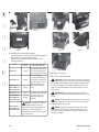
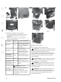
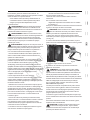
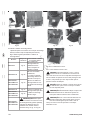
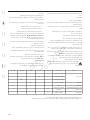
6. Assembly
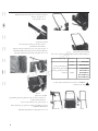
6.1 Assembling the Handle
6.1.1 How to Assemble the Lower Handle.
Assembly of the lower handle by is described in the following
Models
Reference
Image
How to assembly the
lower handle
MP450D20 Fig.8
Fasten lower handle on
the deck by arc plate,
screws and bolts (which
are fixed on deck).
MP625MD21H Fig.9
Fasten lower handle on
handle brackets by bolts
and knobs.
MP550RM21/
MP675RM21H /
MP550RMD21/
MP675RMD21H/
MX675RMD22H
Fig.10

Not for
Reproduction
9
Fig. 8 Fig. 9
Fig. 10
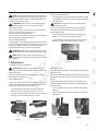
6.1.2 How to Assemble the Upper Handle.
Assembly of the upper handle on to the lower handle is de-
!
NOTE! Make sure the starter rope guide is on the right
handle, when you stand behind the lawnmower.
Models
Reference
Image
How to assembly the
lower handle
MP450D20 Fig.11
Install the upper handle
and fix it to lower handle
by using the star knobs
and the square neck bolts
on each side.
MP625MD21H Fig.12
MP550RM21/
MP675RM21H /
MP550RMD21/
MP675RMD21H/
MX675RMD22H
Fig.13
Fig.11 Fig.12 Fig.13
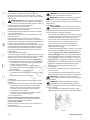
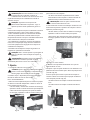
6.1.3 How to Fix the Cables to the Handles
Fix the cables on the handles with the cable clips provided
(see Fig.14):
• Push models: One cable only;
• Self-propelled models: Two cables.
6.2 Attaching the Grass Bag
• Applicable to models with Grass Bag only (see Section
1. Lift rear door with one hand and position the hooks of the
grass bag onto the two plastic sleeves which are installed on
rear door shaft(see Fig.15 and Fig.16).
2. Release rear door to secure the grass bag in position (see
Fig.17).
6.3 Installing Mulch Plug
• Only applicable to models with both rear collect and
-
tions).
1.
Lift the rear door and remove the grass bag, if present.
2. Push the plastic mulch plug into the discharge chute until it
is locked in place (see Fig.18 and Fig.19).
3. Release the rear door to cover the mulch plug (see Fig.20).
Fig. 14
Fig. 15 Fig.16
Fig. 17

Not for
Reproduction
10
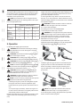
• Only applicable to models with Side Discharge function
(see Section 2. Technical specifications).
Please follow the following table to install the side
Fig. 18 Fig.19
Fig. 20
Models
Reference
Image
How to install the side
discharge deflector
MP450D20 Fig.21
Fix side discharge deflec-
tor on deck by using two
sets of the bolt and screw.
MP625MD21H Fig.22
No tools required;
1. Lift the side discharge
cover with one hand and
put hook features of side
discharge deflector on
shaft of side discharge
cover.
MP550RMD21 /
MP675RMD21H /
MX675RMD22H
Fig.23
MP625MD21H Fig.24
2. Release side discharge
cover to secure side
discharge deflector in
position.
MP550RMD21 /
MP675RMD21H /
MX675RMD22H
Fig.25
MP550RMD21 /
MP675RMD21H /
MX675RMD22H
!
NOTE! To operate rear collect
capable models in side dis-
charge mode (where applicable), the
mulch plug must be installed as
described above and shown in Fig.18,
Fig.19 and Fig.20.
Fig. 21 Fig.22
Fig. 23 Fig.24
Fig. 25
6.5 Engine Oil and Fuel
6.5.1 How to Check and Fill Oil
!
CAUTION!
To prevent damage on engine, the engine is
the oil which complies with the section Oil Recommendations
in operator’s manual of the engine. To extend the life of your
hours of use.
!
WARNING! Before checking the engine oil level or
adding oil, stop engine and place the mower on a level
surface.
!
NOTE! It is essential to comply with the section How To
Check/Add Oil in the operator’s manual for the engine
to check and add oil correctly.
!
NOTE! Running the engine with a low oil level will
cause engine damage. Using non-detergent oil can
shorten the engine’s service life and using 2-stroke oil will
damage the engine.
www.murray.com

Not for
Reproduction
11
6.5.2 How to Add Fuel to the Engine
!
NOTE! To prevent engine damage, engine is shipped
fuel that complies with the section Fuel Recommendations in
operator’s manual for the engine.
!
WARNING! -
mable and explosive. Fire or explosion can cause
severe burns or death:
- Never remove the cap of the fuel tank or add fuel while the
engine is running or when the engine is hot.
- Fill fuel only in a well-ventilated area.
- If fuel is spilled, do not attempt to start the engine but move
the machine away from the area of spillage and avoid creating
any source of ignition until petrol vapors have dissipated.
- Replace all fuel tank and container caps securely.
!
WARNING! Avoid skin to have repeated or prolonged
contact gasoline and avoid inhalation of gasoline vapor.
!
NOTE! Please comply with the section How To Add
Fuel
into your engine.
7. Adjustment
7.1 Setting the Grass Cutting Height
CAUTION! Adjust grass cutting height only when
engine is stopped and spark plug boot is disconnected
with the spark plug.
Refer to section to get cutting
height range of each model.
For model MP450D20
1. Remove the wheels from the deck to take them out of their
current cutting height position by loosening the knob on the
center of the wheel(see Fig.26 and Fig.27):
• On the right hand side (same side as the discharge
• On left hand side wheels (opposite side to the discharge
!
Fig. 26 Fig.27
2. Select a suitable one of the three locations as appropriate
for the desired cutting height:
• The highest hole on the deck will give the highest height
of cut while the lowest hole on the deck will give the high-
est height of cut.
!
NOTE! All four wheels must be set at same level’s
cutting height holes.
3. Securely re-attach the wheels in the selected height of
cut location by pushing the wheel bolt into the hole and
tightening(see Fig.28):
• On the right hand side (same side as the discharge
•
On left hand side wheels (opposite side to the discharge
For all other models
The cutting height is centrally adjusted with the cutting height
adjustment lever:
1. Pull the cutting height adjustment lever away from the deck
until clear of the slot to release it from its current position (see
Fig.29).
2. Move the handle forwards or backwards relative to the
mower and align with slot for the desired cutting height posi-
tion (see Fig.30):
• The slot towards the front of the machine is the lowest
height of.
• The slot towards the front of the machine is the highest
height of cut.
Fig. 28
Fig. 29 Fig.30

Not for
Reproduction
12
7.2 Setting Required Mode
-
NOTE!
components given in the following table for safe opera-
tion in the appropriate mode.
Components required for safe operating con-
figuration in desired function
Mode
Side discharge
deflecto
Grass bag
Mulch plug
Rear
bagging
×
×
Mulching × ×
Side
discharging
×
!
Each time the lawnmower is used, check the operation of the
engine control lever and braking system before starting to mow;
-
gine should stop within 3 seconds.
2. If the engine fails to stop within 3 seconds of release of
the lever, do no use the machine. Take the lawnmower to an
authorized Briggs & Stratton service dealer to have it checked
and adjusted / repaired.
WARNING! The blade continues to rotate for a few sec-
onds after the engine control lever is released.
8.1.1 How to Start the Engine
For starting from cold on models MP450D20:
1. Press the primer bulb for fully 3-5 times.
WARNING! Too many presses of the primer bulb may
10 Troubleshooting.
For all other models or for starting from warm on models
MP450D20 Go directly to step 2.
2. Stand behind the mower. Hold the engine control lever
against the upper handle (see Fig.31 or Fig.32 as appropriate
for the shape of the upper handle on your model).
3. With the right hand, grip the starter cord handle and pull
it gently out about 10-15cm until resistance is felt. Pull the
starter cord quickly to start the engine (see the Fig.33 or
Fig.34 as appropriate for the shape of the upper handle on
your model.)
NOTE!
If the engine fails to start after three pulls, then
repeat the above steps 1 or 2 (as appropriate) to 3.
4. Once the engine is running, gently release the rope handle
back to rest in the starter rope guide.
!
!
8. Operation
8.1 Starting and Stopping the Lawnmower
WARNING! The lawnmower’s exhaust gas contains
toxic substances. Do not run the engine in closed or
poorly ventilated areas.
WARNING! The lawnmower blade begins to rotate as
soon as the engine is started.
WARNING! Before starting engine, check the lawn-
mower blade to make sure that it is securely fastened.
WARNING! Keep hands, feet, hair and clothing away
from all the moving parts of the lawnmower.
NOTE! To start the engine, make sure that the spark plug
WARNING! Running engines produce heat. Engine
Severe thermal burns can occur on contact.
WARNING! The blade continues to rotate for a few sec-
onds after the engine control lever is released.
NOTE! In order to avoid any unintentional start-ups, this
• Running the engine to power the cutting blade requires
the engine control lever to be held against the upper
handle (without an operator present, the machine will not
run).
• To stop the engine (and blade), release the engine con-
trol lever. The lever will return to its original position which
Each time the lawnmower is used, check the operation of the
engine control lever and braking system before starting to
mow;
!
!
!
!
!
!
!
!
Fig. 31 Fig.32
Fig. 33 Fig.34
!
www.murray.com

Not for
Reproduction
13
8.1.2 How to Stop the Engine
-
nism is used each time the operator wishes to stop the blades
• To stop the engine (and blade), release the engine con-
trol lever. The lever will return to its original position which
8.2 Mowing Grass
WARNING! Always follow the strictest safety proce-
dures when using the lawnmower. Carefully read the
safety instructions of this manual before using the lawnmower.
!
WARNING! Before you start to mow, check the engine
start/stop lever several times to be sure that it is
working properly. Ensure that the tension cable can be
smoothly operated (i.e. is not catching or kinking in any way).
!
WARNING! Never open the rear door, side discharge
cover when the engine is running. Serious injury can be
8.2.1 How to Mow Grass-General Advice
1.
For best results, mow grass when it is dry. Wet grass will tend
to clog the blade and the grass collection system.
season or in drought condition.
3. When using the lawnmower in mulching mode, ensure that
wet or long grass. For cutting wet or long grass, regularly stop
the mower to clear the blade and deck with a suitable tool (do
not clear by hand).
4. Plan the area to be cut.
5. Take account of the terrain and / or obstacles.
6. F
adjacent lines. Based on this, select an appropriate position to
start from and position the mower appropriately.
7. Select the required operating mode (rear bagging, side
discharge or mulching options as appropriate for your model
lawnmower for this by following the section 7.2 Setting the
Required Mode.
8.2.2 How to Mow Grass – Lawnmower Operation
1. Once the mower is in position to start mowing, follow the
section 8.1.1How to Start the Engine above to start the en-
gine and run the cutting system.
lever engaged.
3. Commence mowing by moving the lawnmower forwards at
a steady walking pace:
For push models;
• Push the mower forward through the grass to be mown.
For self-propelled models;
• Follow the section 8.2.3 How to Use the Self-Propelled
Function.
8.2.3 How to Empty Grass Bag
• Applicable to models with Grass Bag only (see Section 2.)
As soon as grass debris start to trail the lawn mower, it is time
to empty grass bag.
NOTE!
engine control lever to stop the engine and wait until the
blade has come to a completely stopped rotating.
1. Use one hand to lift up rear door and use the other hand to
grip the grass bag carry handle (see Fig.35).
2. When clear of the lawnmower, release the rear door,
allowing it to automatically spring back and cover the rear
discharging chute.
3. Empty the grass cuttings from the grass bag.
4. Re-attach the grass bag as described in the section 6.2
Attaching the Grass Bag.
NOTE! To ensure that grass cuttings can be collected
into the grass bag, the rear discharge chute and inside
of the mower deck need to be kept clear of any blockage,
such as a build up of grass debris. Do not use hands or feet to
remove grass debris from any area of the mower. If a blockage
is observed, use a suitable tool such as a brush to clear it.
8.2.4 How to Use the Self-Propelled Function (model
MX675RMD22H only)
Once the mower is positioned ready to mow and the engine
is running (keep the engine control lever engaged against the
upper handle), gently push the drive lever forward against the
upper handle (see Fig.36).
The lawnmower will automatically move forward while the
self-propelled drive lever is engaged in this position.
To stop the forward drive of the lawnmower, release the drive
lever.
NOTE! Only use the self-propelled function while mow-
ing in straight lines; always stop the self-propelled drive
and revert to push control while making turns.
!
!
!
Fig. 35 Fig.36
!

Not for
Reproduction
14
9. Maintenance and storge
To maintain the lawnmower’s ability to operate safe and
for maintenance and storage.
WARNING! Before performing any maintenance or
cleaning, stop engine and wait until mower blade come to
a stop totally. Remove the spark plug boot from the spark plug.
9.1 Normal Maintenance Notes
1. Keep all nuts, bolts and screws tight to be sure that the
equipment is in safe working condition.
2. Check the grass catcher frequently for wear or
deterioration.
3. Replace worn or damaged parts for safety.
safety components can damage the lawnmower and injure
the operators seriously.
5. Only use blades and other spare parts recommended by
Briggs & Stratton. The use of non-genuine parts can damage
the machine and injure the operators. Keep the lawnmower in
good working condition.
9.2 Tilting the Lawnmower
For any cleaning or maintenance that involves the underside
of the deck, follow this procedure to tilt the mower to access
this area of the lawnmower:
1. Empty the fuel tank; ideally let the engine run until all the
fuel is used up:
•
Never leave the lawnmower unattended while running.
• Only run in a well-ventilated area.
• If the fuel tank has to be drained, this should be done
outdoors.
2. Tilt the lawnmower sideways:
• Do not tilt by more than 90 degrees.
9.3 Cleaning
The lawnmower should be cleaned thoroughly after every use.
Always clean the lawnmower immediately after use;
• Do not allow grass debris and other debris to become
dry and hard on any of the mower surfaces.
• Dried grass debris and dirt may impair the mowing
operation.
damage to the lawnmower.
9.3.1 How to Clean
For side discharge and collecting models
Clean all grass debris from any discharge chutes (side and /
or rear discharge chute).
For all models
Follow the procedure above in section 9.2 Tilting the
Lawnmower.
Thoroughly clean the underside of the deck.
!
9.4 Engine cleaning & Maintenance
NOTE! Refer to the Operators Manual of the engine for
all engine maintenance.
NOTE! Check and/or replace the engine brake pads in
service agent regularly, only original parts can be used
as replacement.
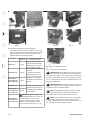
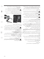
9.5 Blade Maintenance
WARNING! Before performing any maintenance or
cleaning, stop engine and wait until mower blade come to
a stop totally. Remove the spark plug boot from the spark plug.
• To inspect the blade assembly, follow the procedure
above in section 9.2 Tilting the Lawnmower.
• Frequently check the blade (B in Fig.37) for wear or
damage including cracking, bending, deformation etc.
Ensure that the blade cutting edge is sharp (a blunt blade
will roughly tear grass, turning the tips of grass brown).
• Frequently check the bolt (D in Fig.37) that holds the
blade in position; Ensure that the bolt is tightly fastened.
• If the blade hits an object, stop the engine immediately,
disconnect spark plug boot from spark plug. Check the
whole blade assembly which includes the bolt (D in
Fig.37), washer(C in Fig.37), blade (B in Fig.37) and blade
adapter (A in Fig.37).
• If any parts of the blade assembly are found to be
damaged, they should be replaced immediately. Do not
operate the lawnmower with any damaged parts.
• As a minimum, the blade assembly should be replaced
every two years.
• When replacing any component of the blade assembly,
all other components of the blade assembly should be
replaced at the same time.
!
NOTE! The blade assembly must only be removed and
serviced by a Briggs & Stratton authorized service
agent.
NOTE! Use only Briggs & Stratton genuine replacement
or recommended parts. Any other parts may not be
suitable and could endanger safety.
• When installing the blade assembly, the torque on the
blade bolt should be between 45Nm and 55Nm.
!
!
!
!
Fig. 37
www.murray.com

Not for
Reproduction
15
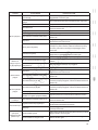
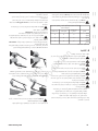
ITEM
SERVICE
PERFORMED
EACH USE 5 Hours 25 Hours 50 Hours 100 Hours
Engine Oil
Check Oil Level X
Initial Oil Change X
Periodic Oil change X*
Air Cleaner Clean or Replace X**
Spark Plug Replace X
Blade, blade adapter, blade
washer, blade bolt
Check For
Wear, Damage&
Replacement
X
Mower Deck
Clean Debris
Accumulation
X
9.6 Wheel Maintenance
At least once per season, lubricate the ball bearings in each
wheel with light oil.
9.7 Storage
9.7.1 Storage for Short Periods
The lawnmower can be stored for short periods of time (less
than 15 days) without performing any storage maintenance.
However before placing the lawnmower into storage area,
always carry out the following steps:
2. Allow the engine to fully cool.
3. Where applicable, ensure the grass bag is empty.
4. Fully clean the lawnmower, including the engine.
mower upright.
6. Store in a safe place which is not accessible by children or
people who are not familiar with operation.
7. The storage area must be well ventilated with no risk of
electric spark.
8. It is recommended to use a fuel stabilizer additive to protect
the fuel tank and engine, particularly when using fuel with
ethanol content (max E10).
petrol storage area free of grass, leaves, or excessive grease.
9.7.2 Store the Lawnmower for Extended Period
!
WARNING! Fuel and its vapors are extremely
severe burns or death:
- Never remove the cap of the fuel tank or add fuel while the
engine is running or when the engine is hot.
- Fill or drain fuel only in a well-ventilated area.
1. Empty the fuel tank; ideally let the engine run until all the
fuel is used up;
•
Never leave the lawnmower unattended while running.
• Only run in a well-ventilated area.
• If the fuel tank has to be drained, this should be done
outdoors.
2. At the end of every season, replace the engine oil with
fresh oil (not applicable on Briggs & Stratton EXi model
engines – for these engines, just Check & Add to ensure that
the engine oil is kept topped up. To replace the oil, follow the
directions in the Operators Manual of the engine.
3. Fully clean the lawnmower, including the engine, paying
cylinder.
4.Wipe clean the deck to protect the paintwork.
mower upright.
6.Store in a safe place which is not accessible by children or
people who are not familiar with operation.
7.The storage area must be well ventilated.
petrol storage area free of grass, leaves, or excessive grease.
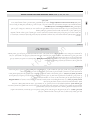
9.8 Maintenance Schedule
Performing routine maintenance correctly on your lawnmower
will ensure of safe and reliable use. Follow the below
maintenance schedule:
*Change oil every 25 hours when operating under heavy load or high temperature.
**Clean more often under dusty conditions or when air debris is present.

Not for
Reproduction
16
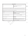
10. Troubleshooting
!
WARNING! Before performing any maintenance or
cleaning, stop engine and wait until mower blade come
to a stop totally. Remove the spark plug boot from the spark
plug.
!
CAUTION! Improper repairs can result in the unsafe
functioning of the lawnmower which can result in
personal injury to the operator, other people or property
damage:
following table should be referred to a Briggs & Stratton
authorized service agent.
• Improper repairs may invalidate the warranty and
additional costs may also be incurred.
• For issues corrective actions listed here that refer to part
of the engine, refer to the operator’s manual of the engine
for further information.
!
NOTE! Use only Briggs & Stratton genuine
replacement or recommended parts. Any other parts
may not be suitable and could endanger safety.
!
NOTE! For removing or installing spark plug, avoid use
of adjustable spanner which can damage spark plug.
Use a dedicated spark plug wrench of the correct size.
!
NOTE! Take care when reinstalling air cleaner
assembly as incorrectly installed air cleaner will allow
dirt into the engine, leading to potential permanent damage.
www.murray.com

Not for
Reproduction
17
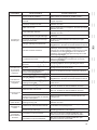
PROBLEM PROBABLE CAUSE CORRECTIVE ACTION
Engine does not
start.
Throttle lever not in the correct position for
the prevailing conditions.
Go to dealer authorized by Briggs&Stratton to move throttle
lever to correct position
Engine stop control lever not engaged Pull engine stop control lever against upper handle.
Fuel tank is empty. Fill tank with fuel-Refer to operator’s manual of the engine
manual of the engine
Spark plug loose. Tighten spark plug-Refer to operator’s manual of the engine
Spark plug boot loose or disconnected
from spark plug.
Install spark plug boot on spark plug.
Gap between electrodes of spark plug is
incorrect.
Refer to engine operator’s manual to set correct gap
Spark plug is defective
Install new genuine Briggs&Stratton spark plug --Refer to
operator’s manual of the engine
Remove spark plug boot from spark plug, remove spark
plug, clean fuel on spark plug, and pull starter rope 5 times
to make fuel in combustion chamber cleared, then install
spark plug and spark plug boot.
Go to dealer authorized by Briggs&Stratton to clean the carbure-
tor or replace one new genuine carburetor
Ignition module fails to provide electric
Contact a Briggs & Stratton authorized service agent.
to start or loses
power.
Dirt, water, or stale fuel tank.
Drain fuel and clean tank. Fill tank with clean, fresh fuel
Vent hole in fuel tank cap is plugged. Clean or replace fuel tank cap.
Engine operates
erratically.
Spark plug is defective.
Install new genuine Briggs&Stratton spark plug --Refer to
operator’s manual of the engine
Gap between electrodes of spark plug is
incorrect.
Refer to engine operator’s manual to set correct gap
Air cleaner element is dirty.
Clean air cleaner element or replace air cleaner element-
Refer to engine operator’s manual
Engine idles poorly.
Air cleaner element is dirty.
Clean air cleaner element or replace air cleaner element-
Refer to engine operator’s manual
Air slots in engine shroud are blocked. Remove debris from slots.
-
gine blower housing are blocked.
Engine skips at
high speed.
Gap between electrodes of spark plug is
too close.
Set gap between electrodes- Refer to engine operator’s
manual
Engine overheats
Remove any debris from slots in shroud, blower housing, air
passages.
Incorrect spark plug.
Obtain correct replacement for original spark plug from by
Briggs & Stratton authorized agent.
Mower vibrates
abnormally
Cutting assembly is loose.
Go to dealer authorized by Briggs&Stratton to tighten blade
with torque between 45N.m-55N.m
Cutting assembly is unbalanced
Go to dealer authorized by Briggs&Stratton to replace with
new same blade.

Not for
Reproduction
18 www.murray.com
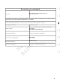
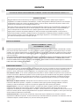
WARRANTY
BRIGGS & STRATTON POWER PRODUCTS GROUP, L.L.C. OWNER WARRANTY POLICY
LIMITED WARRANTY
Briggs & Stratton Power Products Group, LLC will repair or replace, free of charge, any part (s) of the equipment that
is defective in material or workmanship or both. This warranty is effective for the time periods and subject to the condi-
tions stated below. For warranty service, find the nearest Authorized Service Dealer using our dealer locator at www.
BriggsandStratton.com or www.Murray.com.
There is no other express warranty. Implied warranties, including those of merchantability and fitness for a particular pur-
pose, are limited to one year from purchase or to the extent permitted by law. Liability for incidental or consequential dam-
ages are excluded to the extent exclusion is permitted by law.
Some states or countries do not allow limitations on how long an implied warranty lasts, and some states or countries do
not allow the exclusion or limitation of incidental or consequential damages, so the above limitation and exclusion may not
apply to you. This warranty gives you specific legal rights and you may also have other rights which vary from state to state
or country to country.
Most warranty repairs are handled routinely, but sometimes requests for warranty service may not be appropriate. This war-
ranty only covers defects in materials or workmanship. It does not cover damage caused by improper use or abuse, improper
maintenance or repair, normal wear and tear, or stale or unapproved fuel.
Improper Use and Abuse - The proper, intended use of this product is described in the Operator’s Manual. Using the prod-
uct in a way not described in the Operator’s Manual or using the product after it has been damaged will void your warranty.
Warranty is not allowed if the serial number on the product has been removed or the product has been altered or modified in
any way, or if the product has evidence of abuse such as impact damage, or water/chemical corrosion damage.
Improper Maintenance or Repair - This product must be maintained according to the procedures and schedules provided
in the Operator’s Manual, and serviced or repaired using genuine Briggs & Stratton parts. Damage caused by lack of mainte-
nance or use of non-original parts is not covered by warranty.
Normal Wear - Like all mechanical devices, your unit is subject to wear even when properly maintained. This warranty does
not cover repairs when normal use has exhausted the life of a part or the equipment. Maintenance and wear items such as
filters, belts, cutting blades, and brake pads (engine brake pads are covered) are not covered by warranty due to wear charac-
teristics alone, unless the cause is due to defects in material or workmanship.
Stale Fuel - In order to function correctly, this product requires fresh fuel that conforms to the criteria specified in the
Operator’s Manual. Damage caused by stale fuel (carburetor leaks, clogged fuel tubes, sticking valves, etc) is not covered by
warranty.
ABOUT YOUR WARRANTY
WARRANTY PERIOD
The warranty period begins on the date of purchase by the first retail consumer or commercial end user, and continues for the
-
enced commercial use, it shall thereafter be considered as commercial use for purposes of this warranty.
NO WARRANTY REGISTRATION IS NECESSARY TO OBTAIN WARRANTY ON BRIGGS & STRATTON PRODUCTS.
SAVE YOUR PROOF OF PURCHASE RECEIPT. IF YOU DO NOT PROVIDE PROOF OF THE INITIAL PURCHASE DATE AT
THE TIME WARRANTY SERVICE IS REQUESTED, THE MANUFACTURING DATE OF THE PRODUCT WILL BE USED TO
DETERMINE THE WARRANTY PERIOD.

Not for
Reproduction
19
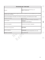
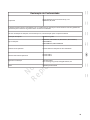
Declaration of Conformity
Corporation
Briggs & Stratton Power Products Group, LLC.
Milwaukee, WI, USA.
The following machine complies with the relevant ISO safety and health requirements as globally recognized for combustion
engine powered lawnmowers.
In case of alteration of the machine, not agreed upon by us, this declaration will lose its validity
Machine Description: Lawn Mower
Machine Type :
MP450D20, MP625MD21H, MP550RM21, MP675RM21H,
MP550RMD21,
MP675RMD21H, MX675RMD22H
Applicable EC Directives EC Machinery Directive:2006/42/EC
Applicable Harmonized Standards
EN ISO 5395-1
EN ISO 5395-2
Certification agency
TUV SUD China
NO.151 Heng Tong Road, Shanghai 200070, P.R. China
Laboratory Qualification ISO17025 certified lab

Not for
Reproduction
Gracias por la compra de este cortacésped Murray™ fabricado conforme a estándares de calidad. Nos complace que haya
depositado su confianza en la marca Murray. Si se utiliza y mantiene de acuerdo con las instrucciones de este manual, el pro-
ducto le proporcionará muchos años de funcionamiento confiable.
Este manual contiene información de seguridad para que tome conciencia de los peligros y riesgos asociados con los
motores, y cómo evitarlos. Esta máquina está diseñada y su uso previsto es solo la finalización del corte de céspedes esta-
blecidos y no cualquier otro propósito. Es importante que lea y comprenda totalmente estas instrucciones antes de tratar de
arrancar u operar este equipo. Guarde estas instrucciones originales para
consulta futura.
Fecha de compra___________________________________________________________________________
Vendedor minorista___________________________________________________________________________________
Número de teléfono del vendedor minoris-
ta_____________________________________________________________________
Equipo
Número de modelo_______________________________________________________________________
Número de serie_______________________________________________________________________
Motor
Modelo________________________Tipo_______________________Código______________________
Copyright © 2015 Briggs & Stratton Power Products Group, LLC.
Milwaukee, WI, EE. UU. Todos los derechos reservados.
MURRAY es una marca comercial de
Briggs & Stratton Power Products Group, LLC.
2 www.murray.com
Sayfa yükleniyor...
Sayfa yükleniyor...
Sayfa yükleniyor...
Sayfa yükleniyor...
Sayfa yükleniyor...
Sayfa yükleniyor...
Sayfa yükleniyor...
Sayfa yükleniyor...
Sayfa yükleniyor...
Sayfa yükleniyor...
Sayfa yükleniyor...
Sayfa yükleniyor...
Sayfa yükleniyor...
Sayfa yükleniyor...
Sayfa yükleniyor...
Sayfa yükleniyor...
Sayfa yükleniyor...
Sayfa yükleniyor...
Sayfa yükleniyor...
Sayfa yükleniyor...
Sayfa yükleniyor...
Sayfa yükleniyor...
Sayfa yükleniyor...
Sayfa yükleniyor...
Sayfa yükleniyor...
Sayfa yükleniyor...
Sayfa yükleniyor...
Sayfa yükleniyor...
Sayfa yükleniyor...
Sayfa yükleniyor...
Sayfa yükleniyor...
Sayfa yükleniyor...
Sayfa yükleniyor...
Sayfa yükleniyor...
Sayfa yükleniyor...
Sayfa yükleniyor...
Sayfa yükleniyor...
Sayfa yükleniyor...
Sayfa yükleniyor...
Sayfa yükleniyor...
Sayfa yükleniyor...
Sayfa yükleniyor...
Sayfa yükleniyor...
Sayfa yükleniyor...
Sayfa yükleniyor...
Sayfa yükleniyor...
Sayfa yükleniyor...
Sayfa yükleniyor...
Sayfa yükleniyor...
Sayfa yükleniyor...
Sayfa yükleniyor...
Sayfa yükleniyor...
Sayfa yükleniyor...
Sayfa yükleniyor...
Sayfa yükleniyor...
Sayfa yükleniyor...
Sayfa yükleniyor...
Sayfa yükleniyor...
Sayfa yükleniyor...
Sayfa yükleniyor...
Sayfa yükleniyor...
Sayfa yükleniyor...
Sayfa yükleniyor...
Sayfa yükleniyor...
Sayfa yükleniyor...
Sayfa yükleniyor...
Sayfa yükleniyor...
Sayfa yükleniyor...
Sayfa yükleniyor...
Sayfa yükleniyor...
Sayfa yükleniyor...
Sayfa yükleniyor...
Sayfa yükleniyor...
Sayfa yükleniyor...
Sayfa yükleniyor...
Sayfa yükleniyor...
Sayfa yükleniyor...
Sayfa yükleniyor...
Sayfa yükleniyor...
Sayfa yükleniyor...
Sayfa yükleniyor...
Sayfa yükleniyor...
Sayfa yükleniyor...
Sayfa yükleniyor...
Sayfa yükleniyor...
Sayfa yükleniyor...
Sayfa yükleniyor...
Sayfa yükleniyor...
Sayfa yükleniyor...
Sayfa yükleniyor...
Sayfa yükleniyor...
Sayfa yükleniyor...
Sayfa yükleniyor...
Sayfa yükleniyor...
Sayfa yükleniyor...
Sayfa yükleniyor...
Sayfa yükleniyor...
Sayfa yükleniyor...
Sayfa yükleniyor...
Sayfa yükleniyor...
Sayfa yükleniyor...
Sayfa yükleniyor...
Sayfa yükleniyor...
Sayfa yükleniyor...
Sayfa yükleniyor...
Sayfa yükleniyor...
Sayfa yükleniyor...
Sayfa yükleniyor...
-
 1
1
-
 2
2
-
 3
3
-
 4
4
-
 5
5
-
 6
6
-
 7
7
-
 8
8
-
 9
9
-
 10
10
-
 11
11
-
 12
12
-
 13
13
-
 14
14
-
 15
15
-
 16
16
-
 17
17
-
 18
18
-
 19
19
-
 20
20
-
 21
21
-
 22
22
-
 23
23
-
 24
24
-
 25
25
-
 26
26
-
 27
27
-
 28
28
-
 29
29
-
 30
30
-
 31
31
-
 32
32
-
 33
33
-
 34
34
-
 35
35
-
 36
36
-
 37
37
-
 38
38
-
 39
39
-
 40
40
-
 41
41
-
 42
42
-
 43
43
-
 44
44
-
 45
45
-
 46
46
-
 47
47
-
 48
48
-
 49
49
-
 50
50
-
 51
51
-
 52
52
-
 53
53
-
 54
54
-
 55
55
-
 56
56
-
 57
57
-
 58
58
-
 59
59
-
 60
60
-
 61
61
-
 62
62
-
 63
63
-
 64
64
-
 65
65
-
 66
66
-
 67
67
-
 68
68
-
 69
69
-
 70
70
-
 71
71
-
 72
72
-
 73
73
-
 74
74
-
 75
75
-
 76
76
-
 77
77
-
 78
78
-
 79
79
-
 80
80
-
 81
81
-
 82
82
-
 83
83
-
 84
84
-
 85
85
-
 86
86
-
 87
87
-
 88
88
-
 89
89
-
 90
90
-
 91
91
-
 92
92
-
 93
93
-
 94
94
-
 95
95
-
 96
96
-
 97
97
-
 98
98
-
 99
99
-
 100
100
-
 101
101
-
 102
102
-
 103
103
-
 104
104
-
 105
105
-
 106
106
-
 107
107
-
 108
108
-
 109
109
-
 110
110
-
 111
111
-
 112
112
-
 113
113
-
 114
114
-
 115
115
-
 116
116
-
 117
117
-
 118
118
-
 119
119
-
 120
120
-
 121
121
-
 122
122
-
 123
123
-
 124
124
-
 125
125
-
 126
126
-
 127
127
-
 128
128


Murray 866079-00 Kullanım kılavuzu
- Kategori
- Çim biçme makinaları
- Tip
- Kullanım kılavuzu
diğer dillerde
- español: Murray 866079-00 Manual de usuario
- français: Murray 866079-00 Manuel utilisateur
- português: Murray 866079-00 Manual do usuário
- English: Murray 866079-00 User manual
İlgili makaleler
Diğer belgeler
-
Makita PLM5120 Kullanım kılavuzu
-
Dolmar PM5120 El kitabı
-
-
Worx WG708E Original Instructions Manual
-
Dolmar PM5600S3C El kitabı
-
WOLF-Garten A 530 A V HW IS Kullanma talimatları
-
-
Simplicity 880805X51 Kullanım kılavuzu
-
Makita LM001J Kullanım kılavuzu
-