
TD002G
EN Cordless Impact Driver INSTRUCTION MANUAL 5
FR Tournevis à Chocs sans Fil MANUEL D’INSTRUCTIONS 18
DE Akku-Schlagschrauber BETRIEBSANLEITUNG 31
IT Avvitatore a massa battente a
batteria ISTRUZIONI PER L’USO 45
NL Accuslagschroevendraaier GEBRUIKSAANWIJZING 59
ES Atornillador de Impacto
Inalámbrico
MANUAL DE
INSTRUCCIONES 73
PT Parafusadeira de Impacto a
Bateria MANUAL DE INSTRUÇÕES 86
DA Akku slagskruemaskine BRUGSANVISNING 99
EL
112
TR KULLANMA KILAVUZU 127

2
2
3
1
1
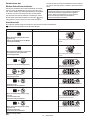
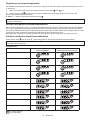
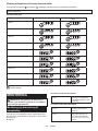
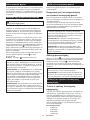
Fig.1
1
2
Fig.2
1
Fig.3
1
AB
Fig.4
1
Fig.5
12
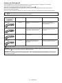
Fig.6
3
12
Fig.7

3
1
Fig.8
Fig.9
Fig.10

4
12
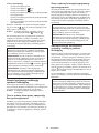
Fig.11
Fig.12
1 2
Fig.13
1 32
Fig.14
3
2
1
Fig.15
1
Fig.16
Fig.17

5ENGLISH
ENGLISH (Original instructions)
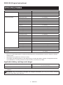
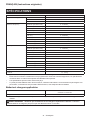
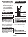
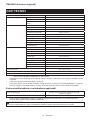
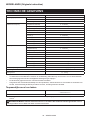
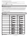
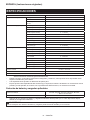
SPECIFICATIONS
Model: TD002G
Fastening capacities Machine screw M4 - M8
Standard bolt M5 - M16
High tensile bolt M5 - M14
No load speed (RPM) 4 (Max impact mode) 0 - 3,700 min-1
3 (Hard impact mode) 0 - 3,200 min-1
2 (Medium impact mode) 0 - 2,100 min-1
1 (Soft impact mode) 0 - 1,100 min-1
Wood mode 0 - 1,800 min-1
T mode (1) 0 - 2,900 min-1
T mode (2) 0 - 3,700 min-1
Bolt mode (1) * 0 - 2,700 min-1
Bolt mode (2) * 0 - 3,700 min-1
Bolt mode (3) * 0 - 3,700 min-1
Impacts per minute 4 (Max impact mode) 0 - 4,600 min-1
3 (Hard impact mode) 0 - 3,600 min-1
2 (Medium impact mode) 0 - 2,600 min-1
1 (Soft impact mode) 0 - 1,400 min-1
Wood mode 0 - 4,600 min-1
T mode (1) -
T mode (2) * 0 - 2,600 min-1
Bolt mode (1) -
Bolt mode (2) * 0 - 4,600 min-1
Bolt mode (3) * 0 - 4,600 min-1
Rated voltage D.C. 36 V - 40 V max
Overall length 119 mm
Net weight 1.7 - 2.9 kg
* Numerical values when rotated clockwise.
without notice.
-
est combinations, according to EPTA-Procedure 01/2014, are shown in the table.
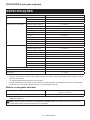
Applicable battery cartridge and charger
BL4020* / BL4025* / BL4040* / BL4050F / BL4080F
Charger DC40RA / DC40RB / DC40RC
residence.
WARNING: Only use the battery cartridges and chargers listed above.

6ENGLISH
Intended use
The tool is intended for screw driving in wood, metal
and plastic.
Noise
-
ing to EN62841-2-2:
Sound pressure level (LpA) : 94 dB (A)
Sound power level (LWA) : 105 dB (A)
NOTE: The declared noise emission value(s) has
been measured in accordance with a standard test
another.
NOTE: The declared noise emission value(s)
exposure.
WARNING: Wear ear protection.
WARNING: The noise emission during actual
value(s) depending on the ways in which the
tool is used especially what kind of workpiece is
processed.
WARNING: Be sure to identify safety mea-
sures to protect the operator that are based on an
estimation of exposure in the actual conditions of
use (taking account of all parts of the operating
cycle such as the times when the tool is switched
trigger time).
Vibration
The vibration total value (tri-axial vector sum) deter-
mined according to EN62841-2-2:
Work mode: impact tightening of fasteners of the maxi-
Vibration emission (ah) : 12.9 m/s2
2
NOTE: The declared vibration total value(s) has been
measured in accordance with a standard test method
NOTE:
WARNING: The vibration emission during
declared value(s) depending on the ways in which
the tool is used especially what kind of workpiece
is processed.
WARNING: Be sure to identify safety mea-
sures to protect the operator that are based on an
estimation of exposure in the actual conditions of
use (taking account of all parts of the operating
cycle such as the times when the tool is switched
trigger time).
Declarations of Conformity
For European countries only
to this instruction manual.
SAFETY WARNINGS
General power tool safety warnings
WARNING Read all safety warnings, instructions,
power tool. Failure to follow all instructions listed below
Save all warnings and instruc-
tions for future reference.
(cordless) power tool.
Cordless impact driver safety
warnings
1. Hold the power tool by insulated gripping
surfaces, when performing an operation
where the fastener may contact hidden wiring.
exposed metal parts of the power tool "live" and
could give the operator an electric shock.
2.
Be sure no one is below when using the tool in
high locations.
3.
4. Wear ear protectors.
5. Do not touch the bit or the workpiece immedi-
ately after operation. They may be extremely
hot and could burn your skin.
6. Keep hands away from rotating parts.
7. Use auxiliary handle(s), if supplied with the
tool.
8. Hold the power tool by insulated gripping
surfaces, when performing an operation where
the cutting accessory may contact hidden
wiring.
tool "live" and could give the operator an electric
shock.
9. Make sure there are no electrical cables, water
pipes, gas pipes etc. that could cause a hazard
if damaged by use of the tool.
SAVE THESE INSTRUCTIONS.
WARNING: DO NOT let comfort or familiarity
with product (gained from repeated use) replace
strict adherence to safety rules for the subject
product.
MISUSE or failure to follow the safety rules stated
in this instruction manual may cause serious
personal injury.

7ENGLISH
Important safety instructions for
battery cartridge
1. Before using battery cartridge, read all instruc-
tions and cautionary markings on (1) battery
charger, (2) battery, and (3) product using
battery.
2. Do not disassemble or tamper with the battery
cartridge.
or explosion.
3. If operating time has become excessively
shorter, stop operating immediately. It may
result in a risk of overheating, possible burns
and even an explosion.
4. If electrolyte gets into your eyes, rinse them
out with clear water and seek medical atten-
tion right away. It may result in loss of your
eyesight.
5. Do not short the battery cartridge:
(1) Do not touch the terminals with any con-
ductive material.
(2) Avoid storing battery cartridge in a con-
tainer with other metal objects such as
nails, coins, etc.
(3) Do not expose battery cartridge to water
or rain.
A battery short can cause a large current
breakdown.
6. Do not store and use the tool and battery car-
tridge in locations where the temperature may
reach or exceed 50 °C (122 °F).
7. Do not incinerate the battery cartridge even if
it is severely damaged or is completely worn
8. Do not nail, cut, crush, throw, drop the battery
cartridge, or hit against a hard object to the
battery cartridge.
9. Do not use a damaged battery.
10. The contained lithium-ion batteries are subject
to the Dangerous Goods Legislation require-
ments.
forwarding agents, special requirement on pack-
aging and labeling must be observed.
For preparation of the item being shipped, consult-
ing an expert for hazardous material is required.
national regulations.
around in the packaging.
11. When disposing the battery cartridge, remove
it from the tool and dispose of it in a safe
place. Follow your local regulations relating to
disposal of battery.
12. Use the batteries only with the products
Installing the batteries to
-
13. If the tool is not used for a long period of time,
the battery must be removed from the tool.
14. During and after use, the battery cartridge may
take on heat which can cause burns or low
temperature burns. Pay attention to the han-
dling of hot battery cartridges.
15. Do not touch the terminal of the tool imme-
diately after use as it may get hot enough to
cause burns.
16. Do not allow chips, dust, or soil stuck into the
terminals, holes, and grooves of the battery
cartridge.
-
17. Unless the tool supports the use near
high-voltage electrical power lines, do not use
the battery cartridge near high-voltage electri-
cal power lines.
18. Keep the battery away from children.
SAVE THESE INSTRUCTIONS.
CAUTION: Only use genuine Makita batteries.
Use of non-genuine Makita batteries, or batteries that
charger.
Tips for maintaining maximum
battery life
1. Charge the battery cartridge before completely
discharged. Always stop tool operation and
charge the battery cartridge when you notice
less tool power.
2. Never recharge a fully charged battery car-
tridge. Overcharging shortens the battery
service life.
3. Charge the battery cartridge with room tem-
perature at 10 °C - 40 °C (50 °F - 104 °F). Let
a hot battery cartridge cool down before
charging it.
4. When not using the battery cartridge, remove
it from the tool or the charger.
5. Charge the battery cartridge if you do not use
it for a long period (more than six months).

8ENGLISH
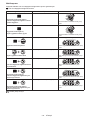
FUNCTIONAL DESCRIPTION
CAUTION: Always be sure that the tool is
before adjusting or checking function on the tool.
Installing or removing battery cartridge
CAUTION:
installing or removing of the battery cartridge.
CAUTION: Hold the tool and the battery car-
cartridge.
while sliding the button on the front of the cartridge.
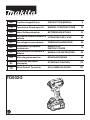
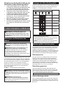
Fig.1: 1. Red indicator 2. Button 3.
CAUTION: Always install the battery cartridge
fully until the red indicator cannot be seen. If not,
CAUTION: Do not install the battery cartridge
forcibly.
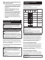
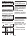
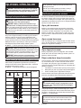
Indicating the remaining battery capacity
-
light up for a few seconds.
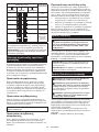
Fig.2: 1. Indicator lamps 2. Check button
Indicator lamps Remaining
capacity
Lighted Blinking
75% to 100%
50% to 75%
25% to 50%
0% to 25%
Charge the
malfunctioned.
NOTE: Depending on the conditions of use and the
NOTE:
Tool / battery protection system
-
-
placed under one of the following conditions:
Overload protection
-
to become overloaded. Then turn the tool on to restart.
Overheat protection
before turning the tool on again.
NOTE: When the tool is overheated, the lamp blinks.
Overdischarge protection
Protections against other causes
that could damage the tool and allows the tool to stop
halt or stop in operation.
1.
Switch action
CAUTION: Before installing the battery car-
tridge into the tool, always check to see that the
switch trigger actuates properly and returns to
the "OFF" position when released.
trigger. Release the switch trigger to stop.
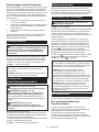
Fig.3: 1. Switch trigger
NOTE:-
ing the switch trigger for about 6 minutes.
NOTE:
buttons do not work.

9ENGLISH
Reversing switch action
CAUTION: Always check the direction of
rotation before operation.
CAUTION: Use the reversing switch only after
the tool comes to a complete stop. Changing the
-
age the tool.
CAUTION: When not operating the tool,
always set the reversing switch lever to the neu-
tral position.
This tool has a reversing switch to change the direction
of rotation. Depress the reversing switch lever from the
A side for clockwise rotation or from the B side for coun-
terclockwise rotation.
When the reversing switch lever is in the neutral posi-
tion, the switch trigger cannot be pulled.
Fig.4: 1. Reversing switch lever
Electric brake
This tool is equipped with an electric brake. If the tool
is released, have the tool serviced at a Makita service
center.
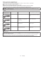
Lighting up the front lamp
CAUTION: Do not look in the light or see the
source of light directly.
Fig.5: 1. Front lamp
Pull the switch trigger to turn on the front lamps. To turn
trigger.
trigger. Within 10 seconds after releasing the switch
trigger, press and hold the button for a few seconds.
on even if the trigger is pulled.
To turn on the lamp status again, press and hold the
button for a few seconds.
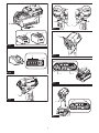
Fig.6: 1. Button 2. Switch panel
NOTE: When the tool is overheated, the front lamps
again.
NOTE:
when the reversing switch lever is not in the neutral
switch trigger, the lamp status is on. When the front
NOTE:
the front lamps. Be careful not to scratch the lens of
Light mode
To turn on the light, set the reversing switch lever in the
neutral position and pull the switch trigger.
depress the reversing switch lever.
NOTE: You cannot change the application mode
while the light mode is on. The lamps on the switch
panel do not turn on when the light mode is on.
NOTE:
change the application mode when the light mode is
on.
NOTE: The light mode does not work when the tool/
Changing brightness
Press the button while the light mode is operating.
button . The brightness will return to the highest when
operating in the lowest brightness. The brightness can
NOTE: The light turns on at the same brightness as
the last setting.
NOTE: The brightness during driving tool will be the
same as the brightness set in the light mode.
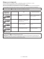
Changing the application mode
What's the application mode?
The application mode is the variation of the driving
This tool features following application modes:
Impact force
• 4 (Max)
• 3 (Hard)
• 2 (Medium)
• 1 (Soft)
Assist type
• Wood mode
• T mode (1)
• T mode (2)
• Bolt mode (1) (clockwise/counterclockwise)
• Bolt mode (2) (clockwise/counterclockwise)
• Bolt mode (3) (clockwise/counterclockwise)
-
ton , , or the quick mode-switching button.
Fig.7: 1. Quick mode-switching button
2. Button 3. Button

10 ENGLISH
mode-switching function).
NOTE: When none of the lamp on the panel is lit,
pull the switch trigger once before pressing the quick
mode-switching button.
NOTE: You will not be able to change the application
one minute. In this case, pull the switch trigger
once and press the button , button , or quick
mode-switching button.
NOTE: Refer to "Registering the application mode"
in "Quick mode-switching function" section for how to
register the application mode.
Quick mode-switching button
The function of the quick mode-switching button varies
-
tion mode to the tool.
Fig.8: 1. Quick mode-switching button
When the application mode is not
registered:
the quick mode-switching button. The front lamps will
-
ing the quick mode-switching button.
When the application mode is registered:
The tool switches between the registered application
press the quick mode-switching button. The front lamps
pressing the quick mode-switching button.
NOTE:
button.
NOTE: Refer to "Registering the application mode"
in "Quick mode-switching function" section for how to
register the application mode.
Disabling the quick mode-switching
button
You can also disable the quick mode-switching button.
After disabling, the quick mode-switching button will not
work for changing the impact force and switching the
application mode.
To disable the quick mode-switching button, press and
hold the quick mode-switching button and the but-
ton at the same time until the all lamps on the panel
blink.
To resume the quick mode-switching button, perform
the same procedure as above again.
NOTE: Registering and erasing the application mode
can be performed even if the quick mode-switching
button is disabled. After registering or erasing the
application mode, the quick mode-switching button
will be activated.

11 ENGLISH
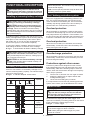
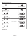
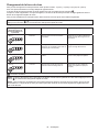
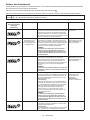
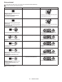
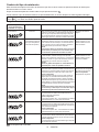
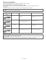
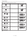
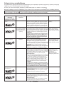
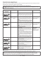
Quick reference
The following table shows the functions of the quick mode-switching button.
indicates the quick mode-switching button.
Button(s) / Purpose Action
(When the application mode is not
registered)
Changing the impact force by the quick
mode-switching button
Press
(When the application mode is regis-
tered)
Switching to the registered application
mode
Press
Registering the application mode
Press and hold (each button) Example: Wood mode is registered
The lamp of desired application mode
blinks.
Erasing the registered application mode
Press and hold (each button)
All impact force grade lamps blink.
Disabling the quick mode-switching
button
Press and hold (each button)
All lamps on the panel blink.
(When the application mode is regis-
tered)
Resuming the quick mode-switching
button
Press and hold (each button) Example: Wood mode is registered
The lamp of desired application mode
blinks.
(When the application mode is not
registered)
Resuming the quick mode-switching
button
Press and hold (each button)
All impact force grade lamps blink.
: The lamp is blinking.

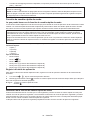
12 ENGLISH
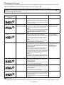
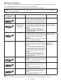
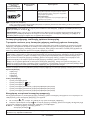
Changing the impact force
You can change the impact force in four steps: 4 (max), 3 (hard), 2 (medium), and 1 (soft).
This allows a tightening suitable to the work.
.
button.
NOTE:-
ton , , or the quick mode-switching button.
Fig.9
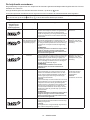
Application mode
(Impact force grade
displayed on panel)
Maximum blows Purpose Example of application
4 (Max) 4,600 min-1 (/min) Tightening with the maximum force
and speed.
Driving screws to underwork materi-
als, tightening long screws or bolts.
3 (Hard) 3,600 min-1 (/min) Tightening with less force and speed
than Max mode (easier to control than
Max mode).
Driving screws to underwork materi-
als, tightening bolts.
2 (Medium) 2,600 min-1 (/min)
needed.
plaster boards.
1 (Soft) 1,400 min-1 (/min) Tightening with less force to avoid
screw thread breakage.
Tightening sash screws or small
screws such as M6.
: The lamp is on.
NOTE: When none of the lamp on the panel is lit, pull the switch trigger once before pressing the button or the
quick mode-switching button.
NOTE:

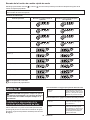
13 ENGLISH
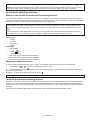
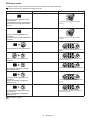
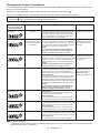
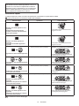
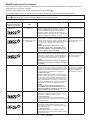
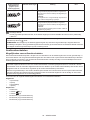
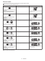
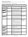
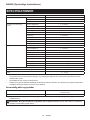
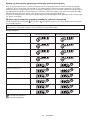
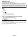
Changing assist type
.
NOTE: , ,
or the quick mode-switching button.
Fig.10
Application mode
(Assist type displayed
on panel)
Maximum blows Feature Purpose
Wood mode * 4,600 min-1 (/min) This mode helps to prevent a screw from falling at
the beginning of driving. The tool drives a screw
to impact, the rotation speed increases and reaches
the maximum speed.
Tightening long screws.
T mode (1) * –
(The tool stops rotating
soon after impact starts.)
This mode helps to prevent the screws from over-tighten-
at the same time. The tool drives a screw with high-speed
rotation and stops soon after the tool starts to impact.
NOTE:
The timing to stop the driving varies depending
on the type of the screw and material to be
driven. Make a test driving before using this
mode.
Driving self-drilling
screws to a thin metal
T mode (2) * 2,600 min-1 (/min) This mode helps to prevent the screws from
breakage and stripping. It also accomplishes quick
drives a screw with high-speed rotation and slows
down the rotation when the tool starts to impact.
NOTE:
Release the switch trigger as soon as the tight-
Driving self-drilling
screws to a thick metal
Bolt mode –Clockwise
with equal torque. The stroke of the switch trigger to
reach maximum speed will become short in this mode.
Counterclockwise
When loosening a bolt with the tool driving in coun-
slows down after the bolt/nut gets enough loosened.
The stroke of the switch trigger to reach maximum
speed will become short in this mode.
NOTE:
The timing to stop the driving varies depending
on the type of the screw and material to be driven.
Make a test driving before using this mode.
Clockwise
Preventing over tighten-
ing of bolts.
Counterclockwise
Loosening bolts.
Bolt mode (1) –Clockwise
started impact blows.
Counterclockwise
as soon as it has stopped impacting.
–
Bolt mode (2) 4,600 min-1 (/min) Clockwise
from the moment that the tool has started impact blows.
Counterclockwise
as soon as it has stopped impacting.
–
Bolt mode (3) 4,600 min-1 (/min) Clockwise
from the moment that the tool has started impact blows.
Counterclockwise
The tool slows down the rotation after it has stopped
impacting.
–
: The lamp is on.
*
When the tool rotates counterclockwise, the impact per minute is the same as in 4 (max) mode, 4,600 min-1 (/min).

14 ENGLISH
NOTE: When none of the lamp on the panel is lit, pull the switch trigger once before pressing the button .
NOTE:
Quick mode-switching function
What you can do with the quick mode-switching function
The quick mode-switching function saves the time for changing the application mode of the tool. You can switch to
EXAMPLE
again.
Even if the tool is in other application mode than T mode, pressing the quick mode-switching button changes to
You can choose one of following application modes for quick mode-switching function:
Impact force
• 4 (Max)
• 3 (Hard)
• 2 (Medium)
• 1 (Soft)
Assist type
• Wood mode
• T mode (1)
• T mode (2)
• Bolt mode (1) (clockwise/counterclockwise)
• Bolt mode (2) (clockwise/counterclockwise)
• Bolt mode (3) (clockwise/counterclockwise)
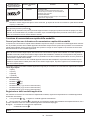
Registering application mode
1. With the button or
2. Press and hold the button and the quick mode-switching button at the same time until the lamp of desired
application mode blinks.
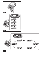
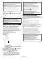
Fig.11: 1. Quick mode-switching button 2. Button
NOTE:
Using the quick mode-switching function
When the tool is in the mode that is not registered, press the quick mode-switching button to switch to the registered
-
tion mode.
The lamp of the registered application mode will blink when using the registered application mode.

15 ENGLISH
Erasing the quick mode-switching function
Press and hold the button and button at the same time until all impact force grade lamps blink.
NOTE: After erasing the quick mode-switching function, the quick mode-switching button works for changing the
impact force.
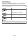
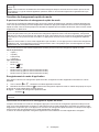
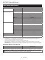
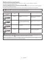
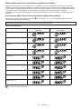
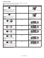
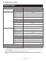
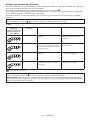
Indication patterns
Application mode While registering the application mode When the registered application mode
turns on
4 (Max)
3 (Hard)
2 (Medium)
1 (Soft)
Wood mode
T mode (1)
T mode (2)
Bolt mode (1)
Bolt mode (2)
Bolt mode (3)
: The lamp is on.
: The lamp is blinking.
ASSEMBLY
CAUTION: Always be sure that the tool is
before carrying out any work on the tool.
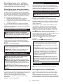
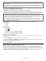
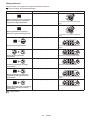
Installing or removing driver bit/
socket bit
socket bit.
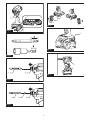
Fig.12
For tool with shallow driver bit hole
A=12mm
B=9mm
bits. Follow the procedure
1. (Note) Bit-piece is not
For tool with deep driver bit hole
A=17mm
B=14mm
bits, follow the procedure 1.
A=12mm
B=9mm
bits, follow the procedure 2.
for installing the bit.

16 ENGLISH
Procedure 1
For tool without one-touch type sleeve
To install the driver bit, pull the sleeve in the direction of
the arrow and insert the driver bit into the sleeve as far
as it will go.
Then release the sleeve to secure the driver bit.
Fig.13: 1. Driver bit 2. Sleeve
For tool with one-touch type sleeve
To install the driver bit, insert the driver bit into the
sleeve as far as it will go.
Procedure 2
In addition to Procedure 1, insert the bit-piece into the
sleeve with its pointed end facing in.
Fig.14: 1. Driver bit 2. Bit-piece 3. Sleeve
To remove the driver bit, pull the sleeve in the direction
of the arrow and pull the driver bit out.
NOTE: If the driver bit is not inserted deep enough
into the sleeve, the sleeve will not return to its original
position and the driver bit will not be secured. In this
-
tions above.
NOTE:
the sleeve and insert it into the sleeve as far as it will
go.
NOTE: After inserting the driver bit, make sure that it
Installing hook
WARNING: Use the hanging/mounting parts
for their intended purposes only, e.g., hanging the
tool on a tool belt between jobs or work intervals.
WARNING: Be careful not to overload the
hook as too much force or irregular overburden
may cause damages to the tool resulting in per-
sonal injury.
CAUTION: When installing the hook, always
If not, the hook
CAUTION: Make sure to hang the tool
securely before releasing your hold.
This can be installed on either side of the tool. To install
the hook, insert it into a groove in the tool housing on
either side and then secure it with a screw. To remove,
loosen the screw and then take it out.
Fig.15: 1. Groove 2. Hook 3. Screw
Using hole
WARNING: Never use the hanging hole for
unintended purpose, for instance, tethering the
tool at high location.
-
Use the hanging hole at the bottom rear of the tool to
hang the tool on a wall using a hanging cord or similar
strings.
Fig.16: 1. Hanging hole
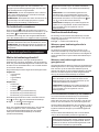
OPERATION
the kind or size of the screw/bolt, the material of the
workpiece to be fastened, etc. The relation between fas-
Fig.17
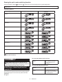
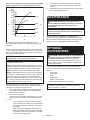
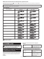
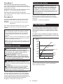
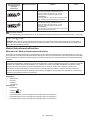
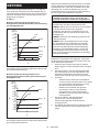
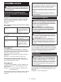
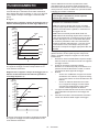
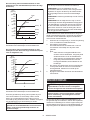
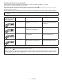
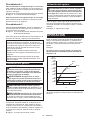
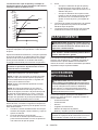
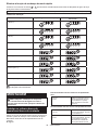
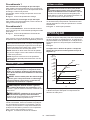
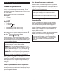
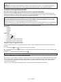
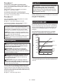
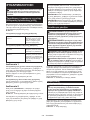
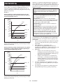
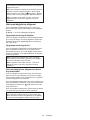
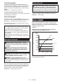
The relation between fastening torque and fasten-
ing time for standard bolt (when impact force is 4)
N•m
(kgf•cm)
M14
M12
M10
M8
(M16)
(M14)
(M12)
(M10)
(M8)
M16
140
(1428)
(1224)
(1020)
(816)
(612)
(408)
(204)
120
100
80
60
40
20
0
23
1
0.60.20.4
1. Fastening time (second) 2. Fastening torque
3. Proper fastening torque corresponding to each bolt
diameter

17
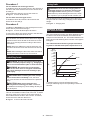
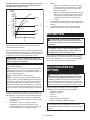
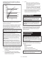
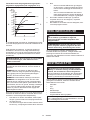
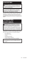
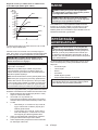
The relation between fastening torque and fastening
time for high tensile bolt (when impact force is 4)
200
180
160
140
120
100
80
60
40
20
N•m
(kgf•cm)
(2040)
(1836)
(1632)
(1428)
(1224)
(1020)
(816)
(612)
(408)
(204)
012
23
1
M14
M12
(M14)
(M12)
(M10)
(M8)
M10
M8
1. Fastening time (second) 2. Fastening torque
3. Proper fastening torque corresponding to each bolt
diameter
the tool on to start operation.
NOTICE: If you use a spare battery to continue
the operation, rest the tool at least 15 min.
NOTE: Use the proper bit for the head of the screw/
NOTE: When fastening M8 or smaller screw, choose
the switch trigger so that the screw is not damaged.
NOTE: Hold the tool pointed straight at the screw.
NOTE:
-
check the torque with a torque wrench.
torque will be reduced.
2. Driver bit or socket bit
Failure to use the correct size driver bit or socket
bit will cause a reduction in the fastening torque.
3. Bolt
class of bolt are the same, the proper fasten-
-
ter of bolt.
• Even though the diameters of bolts are the
of bolt and the bolt length.
4. The manner of holding the tool or the material
torque.
5. Operating the tool at low speed will cause a reduc-
tion in the fastening torque.
MAINTENANCE
CAUTION: Always be sure that the tool is
before attempting to perform inspection or
maintenance.
NOTICE: Never use gasoline, benzine, thinner,
alcohol or the like. Discoloration, deformation or
cracks may result.
To maintain product SAFETY and RELIABILITY,
OPTIONAL
ACCESSORIES
CAUTION: These accessories or attachments
are recommended for use with your Makita tool
accessories or attachments might present a risk of
for its stated purpose.
-
Center.
• Driver bits
• Socket bits
• Hook
• Tool hanger
NOTE:
ENGLISH

18 FRANÇAIS
FRANÇAIS (Instructions originales)
SPÉCIFICATIONS
Modèle : TD002G
Capacités de serrage Vis à machine M4 - M8
Boulon standard M5 - M16
Boulon à haute résistance M5 - M14
Vitesse à vide (tr/min) 4 (Mode de percussion max.) 0 - 3 700 min-1
3 (Mode de percussion rude) 0 - 3 200 min-1
0 - 2 100 min-1
1 (Mode de percussion douce) 0 - 1 100 min-1
Mode bois 0 - 1 800 min-1
Mode T (1) 0 - 2 900 min-1
Mode T (2) 0 - 3 700 min-1
Mode boulon (1) * 0 - 2 700 min-1
Mode boulon (2) * 0 - 3 700 min-1
Mode boulon (3) * 0 - 3 700 min-1
Impacts par minute 4 (Mode de percussion max.) 0 - 4 600 min-1
3 (Mode de percussion rude) 0 - 3 600 min-1
0 - 2 600 min-1
1 (Mode de percussion douce) 0 - 1 400 min-1
Mode bois 0 - 4 600 min-1
Mode T (1) -
Mode T (2) * 0 - 2 600 min-1
Mode boulon (1) -
Mode boulon (2) * 0 - 4 600 min-1
Mode boulon (3) * 0 - 4 600 min-1
Tension nominale 36 V - 40 V c.c. max.
Longueur totale 119 mm
Poids net 1,7 - 2,9 kg
* Valeurs numériques lors de la rotation dans le sens des aiguilles d’une montre.
plus lourde, conformément à la procédure EPTA 01/2014, sont indiquées dans le tableau.
Batterie et chargeur applicables
Batterie BL4020* / BL4025* / BL4040* / BL4050F / BL4080F
* : Batterie recommandée
Chargeur DC40RA / DC40RB / DC40RC
• Certains chargeurs et batteries répertoriés ci-dessus peuvent ne pas être disponibles selon la région où vous
résidez.
AVERTISSEMENT : N’utilisez que les batteries et les chargeurs répertoriés ci-dessus. L’utilisation
d’autres batteries et chargeurs peut provoquer des blessures et/ou un incendie.

19 FRANÇAIS
Utilisations
L’outil est conçu pour le vissage dans le bois, le métal
et le plastique.
Bruit
EN62841-2-2 :
Niveau de pression sonore (LpA) : 94 dB (A)
Niveau de puissance sonore (LWA) : 105 dB (A)
NOTE : La ou les valeurs d’émission de bruit décla-
rées ont été mesurées conformément à la méthode
de test standard et peuvent être utilisées pour com-
parer les outils entre eux.
NOTE : La ou les valeurs d’émission de bruit décla-
rées peuvent aussi être utilisées pour l’évaluation
préliminaire de l’exposition.
AVERTISSEMENT :
Portez un serre-tête antibruit.
AVERTISSEMENT : L’émission de bruit
lors de l’usage réel de l’outil électrique peut être
la façon dont l’outil est utilisé, particulièrement
selon le type de pièce usinée.
AVERTISSEMENT :
Les mesures de sécurité à
prendre pour protéger l’utilisateur doivent être basées
sur une estimation de l’exposition dans des condi-
tions réelles d’utilisation (en tenant compte de toutes
les composantes du cycle d’utilisation, comme par
exemple le moment de sa mise hors tension, lorsqu’il
tourne à vide et le moment de son déclenchement).
Vibrations
Valeur totale de vibrations (somme de vecteur triaxial)
déterminée selon EN62841-2-2 :
Mode de travail : serrage avec impact de vis ou boulon
ne dépassant pas la capacité maximale de l’outil
Émission de vibrations (ah) : 12,9 m/s2
2
NOTE : La ou les valeurs de vibration totales décla-
rées ont été mesurées conformément à la méthode
de test standard et peuvent être utilisées pour com-
parer les outils entre eux.
NOTE : La ou les valeurs de vibration totales décla-
rées peuvent aussi être utilisées pour l’évaluation
préliminaire de l’exposition.
AVERTISSEMENT : L’émission de vibrations
lors de l’usage réel de l’outil électrique peut être
la façon dont l’outil est utilisé, particulièrement
selon le type de pièce usinée.
AVERTISSEMENT :
Les mesures de sécurité à
prendre pour protéger l’utilisateur doivent être basées
sur une estimation de l’exposition dans des condi-
tions réelles d’utilisation (en tenant compte de toutes
les composantes du cycle d’utilisation, comme par
exemple le moment de sa mise hors tension, lorsqu’il
tourne à vide et le moment de son déclenchement).
Déclarations de conformité
Pour les pays européens uniquement
Les déclarations de conformité sont fournies en Annexe
A à ce mode d’emploi.
CONSIGNES DE
SÉCURITÉ
Consignes de sécurité générales
pour outils électriques
AVERTISSEMENT Veuillez lire toutes les
consignes de sécurité, instructions, illustrations
-
trique. Le non-respect de toutes les instructions indi-
quées ci-dessous peut entraîner une électrocution, un
incendie et/ou de graves blessures.
Conservez toutes les mises en
garde et instructions pour réfé-
rence ultérieure.
Le terme « outil électrique » dans les avertissements
fait référence à l’outil électrique alimenté par le secteur
(avec cordon d’alimentation) ou à l’outil électrique fonc-
tionnant sur batterie (sans cordon d’alimentation).
Consignes de sécurité pour le
1. Tenez l’outil électrique par des surfaces de
au cours de laquelle la vis ou le boulon peut
Le
-
métalliques exposées de l’outil et électrocuter
l’opérateur.
2.
Ayez toujours une assise ferme sous vos pieds.
Veillez à ce que personne ne se trouve en
dessous de vous quand vous utilisez l’outil en
hauteur.
3. Tenez votre outil fermement.
4. Portez un casque anti-bruit.
5. Ne touchez pas l’embout ou la pièce immédia-
tement après le fonctionnement. Ils peuvent
être extrêmement chauds et brûler votre peau.
6.
Gardez les mains éloignées des pièces en rotation.
7. Utilisez la ou les poignées auxiliaires, si l’outil
en possède. Toute perte de maîtrise de l’outil
comporte un risque de blessure.
8. Tenez l’outil électrique par des surfaces de
au cours de laquelle l’accessoire de coupe
sous tension peut transmettre du courant dans les
-
cuter l’opérateur.

20 FRANÇAIS
9. -
triques, de conduites d’eau, de conduites
de gaz, etc., présentant un risque s’ils sont
endommagés suite à l’utilisation de l’outil.
CONSERVEZ CES
INSTRUCTIONS.
AVERTISSEMENT : NE vous laissez PAS
sentiment d’aisance et de familiarité avec le
produit, en négligeant le respect rigoureux des
consignes de sécurité qui accompagnent le pro-
duit en question.
La MAUVAISE UTILISATION de l’outil ou l’igno-
rance des consignes de sécurité indiquées
dans ce mode d’emploi peut entraîner de graves
blessures.
Consignes de sécurité importantes
pour la batterie
1. Avant d’utiliser la batterie, lisez toutes les
instructions et précautions relatives (1) au
chargeur de batterie, (2) à la batterie, et (3) au
produit utilisant la batterie.
2.
batterie. Cela pourrait entraîner un incendie, une
chaleur excessive ou une explosion.
3. Cessez immédiatement l’utilisation si le temps
de fonctionnement devient excessivement
voire d’explosion.
4. Si l’électrolyte pénètre dans vos yeux, rin-
cez-les à l’eau claire et consultez immédiate-
ment un médecin. Il y a risque de perte de la
vue.
5. Ne court-circuitez pas la batterie :
(1) Ne touchez les bornes avec aucun maté-
riau conducteur.
(2) Évitez de ranger la batterie dans un
conteneur avec d’autres objets métal-
liques, par exemple des clous, des pièces
de monnaie, etc.
(3) N’exposez pas la batterie à l’eau ou à la
pluie.
Un court-circuit de la batterie peut provoquer
une intensité de courant élevée, une sur-
panne.
6. Ne rangez ni n’utilisez l’outil et la batterie dans
un endroit où la température risque d’atteindre
ou de dépasser 50 °C.
7. Ne jetez pas la batterie au feu même si elle est
sérieusement endommagée ou complètement
épuisée. La batterie peut exploser au contact
du feu.
8. Abstenez-vous de clouer, couper, écraser,
jeter, laisser tomber la batterie, ou de la heur-
ter contre un objet dur. Cela pourrait entraîner
un incendie, une chaleur excessive ou une
explosion.
9. N’utilisez pas la batterie si elle est
endommagée.
10. Les batteries au lithium-ion contenues sont
soumises aux exigences de la législation sur
les marchandises dangereuses.
Lors du transport commercial par des tierces
parties ou des transitaires par exemple, des exi-
d’emballage doivent être respectées.
Pour la préparation de l’article expédié, il est
nécessaire de consulter un expert en matériau
dangereux. Veuillez également respecter les
réglementations nationales susceptibles d’être
plus détaillées.
Recouvrez les contacts exposés avec du ruban
adhésif ou du ruban de masquage et emballez la
batterie de telle sorte qu’elle ne puisse pas bouger
dans l’emballage.
11. Lors de la mise au rebut de la batterie, reti-
rez-la de l’outil et jetez-la en lieu sûr. Suivez les
réglementations locales en matière de mise au
rebut des batteries.
12. Utilisez les batteries uniquement avec les
L’insertion de
batteries dans des produits non conformes peut
provoquer un incendie, une chaleur excessive,
13. Lorsque vous n’utilisez pas l’outil pendant une
période prolongée, la batterie doit être retirée
de l’outil.
14. Pendant et après l’utilisation, la batterie peut
compris en cas de température relativement
basse. Manipulez les batteries chaudes avec
précaution.
15. Ne touchez pas la borne de l’outil immédiate-
ment après utilisation car elle peut être assez
chaude pour provoquer des brûlures.
16. Évitez que des copeaux, de la poussière ou
du sol adhèrent aux bornes, aux trous et aux
rainures de la batterie. Cela peut provoquer un
qui peut entraîner des brûlures ou des blessures.
17. À moins que l’outil prenne en charge un tel
usage, n’utilisez pas la batterie à proximité de
lignes électriques haute tension. Cela pourrait
ou la batterie.
18. Conservez la batterie hors de portée des
enfants.
CONSERVEZ CES
INSTRUCTIONS.
ATTENTION : N’utilisez que des batteries
Makita d’origine. L’utilisation de batteries de marque
-
voquer l’explosion des batteries, ce qui présente un
risque d’incendie, de dommages matériels et corpo-
rels. Cela annulera également la garantie Makita pour
l’outil et le chargeur Makita.
Sayfa yükleniyor...
Sayfa yükleniyor...
Sayfa yükleniyor...
Sayfa yükleniyor...
Sayfa yükleniyor...
Sayfa yükleniyor...
Sayfa yükleniyor...
Sayfa yükleniyor...
Sayfa yükleniyor...
Sayfa yükleniyor...
Sayfa yükleniyor...
Sayfa yükleniyor...
Sayfa yükleniyor...
Sayfa yükleniyor...
Sayfa yükleniyor...
Sayfa yükleniyor...
Sayfa yükleniyor...
Sayfa yükleniyor...
Sayfa yükleniyor...
Sayfa yükleniyor...
Sayfa yükleniyor...
Sayfa yükleniyor...
Sayfa yükleniyor...
Sayfa yükleniyor...
Sayfa yükleniyor...
Sayfa yükleniyor...
Sayfa yükleniyor...
Sayfa yükleniyor...
Sayfa yükleniyor...
Sayfa yükleniyor...
Sayfa yükleniyor...
Sayfa yükleniyor...
Sayfa yükleniyor...
Sayfa yükleniyor...
Sayfa yükleniyor...
Sayfa yükleniyor...
Sayfa yükleniyor...
Sayfa yükleniyor...
Sayfa yükleniyor...
Sayfa yükleniyor...
Sayfa yükleniyor...
Sayfa yükleniyor...
Sayfa yükleniyor...
Sayfa yükleniyor...
Sayfa yükleniyor...
Sayfa yükleniyor...
Sayfa yükleniyor...
Sayfa yükleniyor...
Sayfa yükleniyor...
Sayfa yükleniyor...
Sayfa yükleniyor...
Sayfa yükleniyor...
Sayfa yükleniyor...
Sayfa yükleniyor...
Sayfa yükleniyor...
Sayfa yükleniyor...
Sayfa yükleniyor...
Sayfa yükleniyor...
Sayfa yükleniyor...
Sayfa yükleniyor...
Sayfa yükleniyor...
Sayfa yükleniyor...
Sayfa yükleniyor...
Sayfa yükleniyor...
Sayfa yükleniyor...
Sayfa yükleniyor...
Sayfa yükleniyor...
Sayfa yükleniyor...
Sayfa yükleniyor...
Sayfa yükleniyor...
Sayfa yükleniyor...
Sayfa yükleniyor...
Sayfa yükleniyor...
Sayfa yükleniyor...
Sayfa yükleniyor...
Sayfa yükleniyor...
Sayfa yükleniyor...
Sayfa yükleniyor...
Sayfa yükleniyor...
Sayfa yükleniyor...
Sayfa yükleniyor...
Sayfa yükleniyor...
Sayfa yükleniyor...
Sayfa yükleniyor...
Sayfa yükleniyor...
Sayfa yükleniyor...
Sayfa yükleniyor...
Sayfa yükleniyor...
Sayfa yükleniyor...
Sayfa yükleniyor...
Sayfa yükleniyor...
Sayfa yükleniyor...
Sayfa yükleniyor...
Sayfa yükleniyor...
Sayfa yükleniyor...
Sayfa yükleniyor...
Sayfa yükleniyor...
Sayfa yükleniyor...
Sayfa yükleniyor...
Sayfa yükleniyor...
Sayfa yükleniyor...
Sayfa yükleniyor...
Sayfa yükleniyor...
Sayfa yükleniyor...
Sayfa yükleniyor...
Sayfa yükleniyor...
Sayfa yükleniyor...
Sayfa yükleniyor...
Sayfa yükleniyor...
Sayfa yükleniyor...
Sayfa yükleniyor...
Sayfa yükleniyor...
Sayfa yükleniyor...
Sayfa yükleniyor...
Sayfa yükleniyor...
Sayfa yükleniyor...
Sayfa yükleniyor...
Sayfa yükleniyor...
Sayfa yükleniyor...
Sayfa yükleniyor...
-
 1
1
-
 2
2
-
 3
3
-
 4
4
-
 5
5
-
 6
6
-
 7
7
-
 8
8
-
 9
9
-
 10
10
-
 11
11
-
 12
12
-
 13
13
-
 14
14
-
 15
15
-
 16
16
-
 17
17
-
 18
18
-
 19
19
-
 20
20
-
 21
21
-
 22
22
-
 23
23
-
 24
24
-
 25
25
-
 26
26
-
 27
27
-
 28
28
-
 29
29
-
 30
30
-
 31
31
-
 32
32
-
 33
33
-
 34
34
-
 35
35
-
 36
36
-
 37
37
-
 38
38
-
 39
39
-
 40
40
-
 41
41
-
 42
42
-
 43
43
-
 44
44
-
 45
45
-
 46
46
-
 47
47
-
 48
48
-
 49
49
-
 50
50
-
 51
51
-
 52
52
-
 53
53
-
 54
54
-
 55
55
-
 56
56
-
 57
57
-
 58
58
-
 59
59
-
 60
60
-
 61
61
-
 62
62
-
 63
63
-
 64
64
-
 65
65
-
 66
66
-
 67
67
-
 68
68
-
 69
69
-
 70
70
-
 71
71
-
 72
72
-
 73
73
-
 74
74
-
 75
75
-
 76
76
-
 77
77
-
 78
78
-
 79
79
-
 80
80
-
 81
81
-
 82
82
-
 83
83
-
 84
84
-
 85
85
-
 86
86
-
 87
87
-
 88
88
-
 89
89
-
 90
90
-
 91
91
-
 92
92
-
 93
93
-
 94
94
-
 95
95
-
 96
96
-
 97
97
-
 98
98
-
 99
99
-
 100
100
-
 101
101
-
 102
102
-
 103
103
-
 104
104
-
 105
105
-
 106
106
-
 107
107
-
 108
108
-
 109
109
-
 110
110
-
 111
111
-
 112
112
-
 113
113
-
 114
114
-
 115
115
-
 116
116
-
 117
117
-
 118
118
-
 119
119
-
 120
120
-
 121
121
-
 122
122
-
 123
123
-
 124
124
-
 125
125
-
 126
126
-
 127
127
-
 128
128
-
 129
129
-
 130
130
-
 131
131
-
 132
132
-
 133
133
-
 134
134
-
 135
135
-
 136
136
-
 137
137
-
 138
138
-
 139
139
-
 140
140


diğer dillerde
- español: Makita TD002G Manual de usuario
- français: Makita TD002G Manuel utilisateur
- italiano: Makita TD002G Manuale utente
- Deutsch: Makita TD002G Benutzerhandbuch
- português: Makita TD002G Manual do usuário
- dansk: Makita TD002G Brugermanual
- Nederlands: Makita TD002G Handleiding
İlgili makaleler
-
Makita DTD172 Cordless Impact Driver Kullanım kılavuzu
-
Makita DTW300 Kullanım kılavuzu
-
-
-
Makita TW007G Kullanım kılavuzu
-
-
-
-
Makita DTW284 Kullanım kılavuzu
-
Makita DTP131 Kullanım kılavuzu