
A division of the WIKA Group
Operating instructions
Kullanım kılavuzu
GB
Bypass level indicator model BNA
Bypass Seviye Göstergesi Model BNA
TR
Bypass level indicator, model BNA with option level
sensor and magnetic switch

GB
TR
2
KSR KUEBLER Kullanım kılavuz Bypass-Seviye göstergesi – BNA
based on 11/2012 GB/D
Operating instructions bypass level indicator
Model BNA Page 3-16
Bypass seviye göstergesi kullanım kılavuzu
Model BNA Sayfa 17-30

GB
KSR KUEBLER Kullanım kılavuz Bypass-Seviye göstergesi – BNA
3
based on 11/2012 GB/D
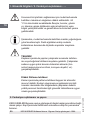
WARNING!
Instructions on correct installation and proper operation.
Non-observance of these instructions can lead to
malfunction or damage.
DANGER!
Instructions which must be complied with to avoid injury or
property damage.
Information
Facts and information concerning proper operation.
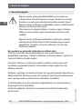
1. Safety instructions 4
2. Description of functions and design 6
3. Installation and commissioning 7
4. Maintenance 15
5. Error detection 16
Contents
Contents

GB
4
KSR KUEBLER Kullanım kılavuz Bypass-Seviye göstergesi – BNA
based on 11/2012 GB/D
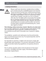
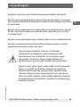
1. Safety instructions
Please read these instructions carefully before installing
and commissioning the model BNA bypass level indicator.
These instructions are directed to trained personnel imple-
menting the assembly, installation and set-up of the system.
The bypass level indicator serves for continuously measu-
ring the level of liquids in vessels. Use it for no purpose
other than this. No liability will be assumed by the manufac-
turer for damage resulting from use other than specied!
The bypass level indicator has been designed, manufactu-
red and tested in accordance with the state of art and the
accepted safety regulations. Notwithstanding this, certain
risks might be involved.
The following safety instructions should, therefore, be observed:
Do not modify, supplement or change the bypass level indicator unless
with manufacturer’s express approval. Unauthorised changes or
non-permitted use will result in immediate loss of warranty or liability
claims.
The installation, operation and maintenance must be performed by
expert and authorised personnel only. The required expertise must be
obtained by regular training.
It is imperative for operators, installers and servicers to comply with
all applicable safety regulations. This provision shall extend to all local
safety and accident preventing regulations not expressly referred to
herein.
Prior to starting operation please check all devices for their proper
connection, operability and power supply. This shall also apply to
assemblies coupled thereto.
1. Safety instructions

GB
KSR KUEBLER Kullanım kılavuz Bypass-Seviye göstergesi – BNA
5
based on 11/2012 GB/D
The general operating instructions of all devices as used must be
abided by.
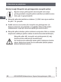
Measures must be taken preventing personal injuries and damage to
property from occurring in case of a defective condition of the bypass
level indicators.
The bypass level indicator must not be operated in the direct vicinity of
ferromagnetic environments (min. distance 50 mm) or strong electroma-
gnetic elds (min. distance 1 m).
The bypass level indicator must not be exposed to heavy mechanical
strain.
The maximum power and voltage values for the intrinsically safe opera-
tion as specied in the assembling and operating instructions should be
adhered to.
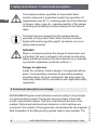
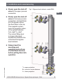
The safe operation of the system with a view to
pressure and temperature of the materials as emplo-
yed shall be the operator’s responsibility.
The medium to be monitored must not be heavily soiled
or contain coarse particles. It must not tend to stick or
crystallise, as otherwise the perfect function cannot be
guaranteed.
The bypass level indicators may only be used in accordance
with the maximum values for pressure and temperature as
stated on the product label. Exceeding these parameters
can lead to malfunctions or to the destruction of the bypass
level indicator and may cause personal injury or damage to
property. All materials of the bypass tube and the oat must
be resistant to the medium to be monitored.
1. Safety instructions

GB
6
KSR KUEBLER Kullanım kılavuz Bypass-Seviye göstergesi – BNA
based on 11/2012 GB/D
The maximum values specied on the product label
must be observed to guarantee trouble-free operation. At
temperatures over 60 °C, a warning sign has to be attached
to anges, tubes, case etc., warning explicitly of the danger
of burning and suitable protective measures must also be
taken.
The oat has been designed for the medium density
specied on the product label. When the oat is used in
liquids with another specic weight, deviations can occur
during measurement.
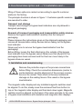
DANGER!
Work in containers involves the danger of intoxication and
suocation. No work is allowed to be carried out unless by
taking suitable personal protective measures (e.g. respirato-
ry protection apparatus, protective outt etc.).
Danger of explosion
Inside the container, there is danger of an explosive atmos-
phere. Corresponding measures for preventing sparking
should be taken. No work is allowed in this area unless by
technically skilled sta in accordance with applicable safety
regulations.
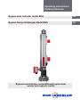
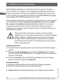
2. Functional description and design
KSR KUEBLER bypass level indicators work according to the principle
of communicating vessels. The bypass vessel contains a oat with
a built-in permanent magnet. This rises and falls with the level of the
medium. Optical and electrical level indicators or limit switches are
mounted to the outside of the bypass tube and actuated by the magnetic
eld. Evaluation of the lling level by guided radar is also possible. The
1. Safety instructions / 2. Functional description ...

GB
KSR KUEBLER Kullanım kılavuz Bypass-Seviye göstergesi – BNA
7
based on 11/2012 GB/D
tting of these options is carried out according to specic customer
wishes in the factory.
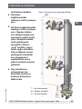
The principle structure is shown in gure 1. Customer-specic versions
are executed to order.
2. Functional description and ... / 3. Installation and ...
Transport and storage
Transport and storage for bypass level indicators are only allowed in
designed packaging.
Removal of transport packaging and transportation safety devices
Remove the bypass level indicator carefully from the transport
packaging.
Please observe the instructions given on the shipment packaging and
remove all transportation safety devices before taking out the bypass
level indicator.
Never use force to remove the bypass level indicator from the
packaging!
Before tting, loosen the oat attached on the outside of the bypass
level indicator from the bypass vessel. Make sure that all parts of the
packaging have been removed and the oat can move freely in the
bypass reference vessel.
3. Installation and commissioning
Remove the protective caps on the process connections
before tting. Check the connection dimensions (centre to
centre distance) and the alignment of the process connec-
tions on the vessel. There must not be any mechanical
damage on the sealing faces of the vessel or the bypass
level indicator.
The magnetic roller display and any installed magnetic switches must
be aligned. To do this, slowly move the enclosed oat from bottom to
top on the magnetic roller display and then back down again. Magnetic
switches must be aligned on the basis of the same principle. In the case
of bypass level indicators with insulation and magnetic roller displays

GB
8
KSR KUEBLER Kullanım kılavuz Bypass-Seviye göstergesi – BNA
based on 11/2012 GB/D
3. Installation and commissioning
The bypass level indicator is mounted in a vertical position on the vessel
to be monitored using the process connections (1) provided. Seals
(2), screws (3), washers (4) and nuts (5) suitable for the process
connection must be used. Choose a seal with a suitable corrosion
resistance. If necessary, shut-o valves must be mounted between the
vessel and the bypass.
Please heed the usual torque values of screws used in
pipetting work. The bypass level indicator must be installed
without tension. Suitable seals must be used. Care must
be taken that the seal material is resistant to the medium
and its vapours as well as to the temperature and pressure
loads to be expected.
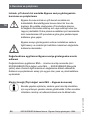
Installing the oat
■
Clean the oat of anything stuck on it in the area of the oat magnet
system
■
Remove the base ange (7) and insert the oat (6) into the tube
from the bottom (the marking "top" or a legible model code marks the
top side of the oat)
■
Place the seal (9) onto the base ange. Replace the base ange
and x it in place using the screws (8)
Commissioning
If the bypass level indicator is tted with shut-o valves between
process connections and tank, proceed as follows.
■
Close draining and bleeding ttings on the bypass level indicator
with Plexiglass attachments, the oat must be moved up and down
inside the tube. For magnetic roller displays with ushing connections,
these connections must have an airtight seal. Please refer in this case
to the mounting and operating instructions for KSR KUEBLER magnetic
roller displays with ushing connections as well.

GB
KSR KUEBLER Kullanım kılavuz Bypass-Seviye göstergesi – BNA
9
based on 11/2012 GB/D
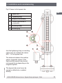
3. Installation and commissioning
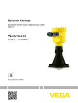
Fig. 1: Bypass level indicator, model BNA
T = upper projection
M = centre to centre distance
U = lower projection
■
Slowly open the shut-o
valve at the upper process
connection
■
Slowly open the shut-o
valve at the lower process
connection. As liquid ows
into the bypass vessel,
the oat oats to the top.
The magnetic system
turns the magnetic rollers
of the optical indicator
from „light“ to „dark“.
The current lling level
is shown after liquid
equalisation between the
vessel and the bypass
level indicator
■
Always heed the
mounting and
operating instructions
of attachment devices
before putting them into
operation

GB
10
KSR KUEBLER Kullanım kılavuz Bypass-Seviye göstergesi – BNA
based on 11/2012 GB/D
3. Installation and commissioning
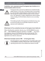
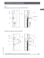
Installation and commissioning of the bypass level indicator in a
heated double-walled version
The bypass tube can also be delivered in a heated double-
walled version. In this case, the bypass tube is surrounded
by a second tube. Heated liquid or steam (heat carrier) can
ow through this double-sheathed space via two connec-
tions. The materials for higher temperatures must be desig-
ned according to AD information sheets in non-corroding
qualities.
The heating sheath of the bypass level indicators may only
be used according to the specied maximum values for
pressure and temperature.
Attachment of the evaluation devices to the bypass level indicator
When attaching the evaluation devices (e.g.: KSR KUEBLER sensors
MG …, KSR KUEBLER magnetic switches) to the BNA …, the respec-
tive maximum values of the eld instrument must be heeded. The
applicable laws or directives for the use or the planned purpose of
application must also be observed.
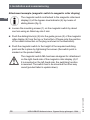
Attachment example (sensor MG… to the bypass tube)
This description is only intended as an orientation aid for the
local installation situation. Please refer to the mounting and
operating instructions of the attachment devices as well.

GB
KSR KUEBLER Kullanım kılavuz Bypass-Seviye göstergesi – BNA
11
based on 11/2012 GB/D
3. Installation and commissioning
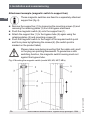
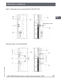
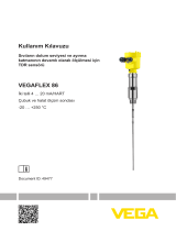
Fig. 2: Sensor to the bypass tube
1 Sensor MG ...
2 Tightening strap
3 Magnetic roller display
4 Cheese-head screw or
comparable
5 Mounting clamp
6 Mounting lug
Use the tightening strap or mounting
clamp (pos. 5) to attach the sensor
MG … to the bypass tube.
The distance between the position
sensor (magnetic system in the
oat) and the sensor tube should
not exceed 8 mm depending on the
magnetic system.
The bypass tube must never be
scored or drilled into or welded
directly.

GB
12
KSR KUEBLER Kullanım kılavuz Bypass-Seviye göstergesi – BNA
based on 11/2012 GB/D
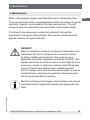
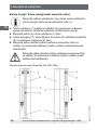
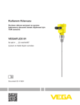
Attachment example (magnetic switch to magnetic roller display)
The magnetic switch is attached to the magnetic roller level
display (4) of the bypass level indicator (6) by means of
sliding blocks (g. 3).
■
Loosen the mounting screws (1) on the magnetic switch by about
one turn using an Allen key size 3 mm
■
Push the sliding block(s) (2) into the guide groove (3) of the magnetic
roller display (4) from the top or the bottom. (Please note the position
of the cable connection or the plug as shown in the illustration)
■
Push the magnetic switch to the height of the required switching
point and x in place by tightening the screws (the switch point is
marked on the product label).
The magnetic switch MA has been designed for attachment
on the right-hand side of the magnetic roller display (4). If
it is mounted on the left-hand side, the switching function
is reversed. The switch has to be mounted the other way
round (product label is upside down).
3. Installation and commissioning

GB
KSR KUEBLER Kullanım kılavuz Bypass-Seviye göstergesi – BNA
13
based on 11/2012 GB/D
3. Installation and commissioning
Fig. 3:
Mounting the magnetic switch (model M, ME, MST, MT)
Mounting the magnetic switch (model MA)
Switch point

GB
14
KSR KUEBLER Kullanım kılavuz Bypass-Seviye göstergesi – BNA
based on 11/2012 GB/D
Attachment example (magnetic switch to support bar)
These magnetic switches are xed to a separately attached
support bar (g. 4).
■
Remove the support bar (1) by loosening the mounting screws (2) and
removing the retaining plates (3) from the bypass stand seat
■
Push the magnetic switch (4) onto the support bar (1)
■
Attach the support bar (1) to the bypass tube (5) again using the
retaining plates (3) and mounting screws (2)
■
Push the magnetic switch to the height of the required switch point
and x in place by tightening the screws (6) (the switch point is
marked on the product label)
Please make sure during mounting that the cable entry and/
or the plug are pointing downwards. To guarantee a safe
switching function, the magnetic switch housing must rest
against the bypass tube.
3. Installation and commissioning
Fig. 4: Mounting the magnetic switch (model MS, MV, MVT, MEx)

GB
KSR KUEBLER Kullanım kılavuz Bypass-Seviye göstergesi – BNA
15
based on 11/2012 GB/D
4. Maintenance
When used properly, bypass level indicators work maintenance-free.
They must be subjected to visual inspection within the context of regular
servicing, however, and included in the tank pressure test. (The test
pressure must not exceed the value specied on the product label!)
If the liquid to be measured contains dirt particles that could be
deposited in the bypass level indicator, the operator should clean the
bypass chamber at regular intervals.
4. Maintenance
DANGER!
Work on containers involves the danger of intoxication and
suocation. No work is allowed to be carried out unless
by taking suitable personal protective measures (e.g.
respiratory protection apparatus, protective outt etc.). The
bypass vessel can be under pressure. There might be a hot,
poisonous, caustic or explosive medium inside the bypass
vessel. Potential injury hazard due to splashing liquid,
burns to hands, arms, feet and face are possible, as well as
chemical burns, poisoning or explosions. Vessel pressure
has to be released before opening.
Perfect functioning of the bypass level indicator can only be
guaranteed when original accessories and spare parts are
used.

GB
16
KSR KUEBLER Kullanım kılavuz Bypass-Seviye göstergesi – BNA
based on 11/2012 GB/D
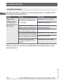
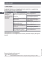
5. Trouble shooting
5. Trouble shooting
The following table contains the most frequent causes of faults and the
necessary countermeasures.
Fault Cause Measure
Bypass level
indicator cannot
be tted at the
planned place on
the vessel
Thread size or ange size of
the bypass level indicator do
not correlate
Modication of the vessel
Return to the factory
Thread on the fastening
sleeve on the vessel is faulty
Rework the thread or replace
the fastening sleeve
Mounting thread on the by-
pass level indicator is faulty
Return to the factory
Centre to centre distance of
the vessel does not correlate
with the bypass level indicator
Modication of the vessel
Return to the factory
Process connections are
not attached parallel to one
another
Modication of the vessel
Please contact us if you have any diculties. We will be happy to help
any way we can.

TR
KSR KUEBLER Kullanım kılavuz Bypass-Seviye göstergesi – BNA
17
based on 11/2012 GB/D
UYARI!
Kurallara uygun montaj ve usulüne uygun kullanım için
uyarılar. Uyulmaması durumunda hatalı işlevler veya arızalar
meydana gelebilir.
TEHLİKE!
Uyulmaması durumunda şahsi ve maddi hasarlara neden
olabilecek uyarılar.
Bilgi
Kurallara uygun kullanım için veriler ve bilgiler.
1. Güvenlik bilgileri 18
2. Fonksiyon açıklaması ve yapısı 20
3. Kurulum ve çalıştırma 21
4. Bakım 29
5. Hata tespiti 30
İçindekiler
İçindekiler

TR
KSR KUEBLER Kullanım kılavuz Bypass-Seviye göstergesi – BNA
18
based on 11/2012 GB/D
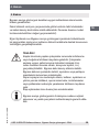
1. Güvenlik bilgileri
Bypass seviye göstergesi Model BNA‘yı kurmadan ve
çalıştırmadan önce bu kılavuzu okuyun. Bu kılavuz montajı,
kurulumu ve ayarı gerçekleştirecek yetkili personel içindir.
Bypass seviye göstergesi, kaplardaki sıvıların sürekli doluluk
seviyesi ölçümü görevini görür.
Onu sadece bu amaçla kullanın. Usulüne uygun olmayan
kullanım sonucunda oluşan hasarlardan üretici sorumlu
değildir!
Bypass seviye göstergesi teknolojinin düzeyine ve kabul
edilmiş emniyet teknolojisine dair kurallara uygun olarak
geliştirilmiş, üretilmiş ve kontrol edilmiştir. Yine de alet
tehlike arz edebilir.
Bu nedenle şu güvenlik talimatlarına dikkat edin:
Üreticiye önceden danışmadan Bypass seviye göstergesinde
değişiklikler yapmayın. Yetkisiz müdahale ve izinsiz kullanım, garanti ve
tazminat hakkını ortadan kaldırır.
Kurulum, kullanım ve çalıştırma sadece yetkili bir uzman personel
tarafından gerçekleştirilmelidir. Uzmanlıklar düzenli eğitim ile elde
edilmiş olmalıdır.
Kullanan, ayarlayan ve çalıştıran kişiler tüm geçerli güvenlik talimatlarına
dikkat etmelidir. Bunların içerisine bu kullanım kılavuzunda belirtilmemiş
olan yerel güvenlik ve kaza önleme talimatları da dahildir.
Çalıştırılmadan önce tüm cihazların bağlantılarının ve fonksiyonlarının
doğruluğu kontrol edilmelidir.
Ardından bağlanan cihazların da olmak üzere elektrik beslemesini
kontrol edin.
1. Güvenlik bilgileri

TR
KSR KUEBLER Kullanım kılavuz Bypass-Seviye göstergesi – BNA
19
based on 11/2012 GB/D
Kullanılan cihazların genel kullanım kılavuzlarına dikkat edilmelidir.
Bypass seviye göstergesinin bozulması durumunda kişiler ve nesneler
için meydana gelebilecek tehlikelerin engellenmesini sağlayacak önlem-
ler alınmalıdır.
Bypass seviye göstergesini ferromanyetik çevre yakınında (min. mesafe
50 mm) veya güçlü elektromanyetik alanların yakınında (min. mesafe 1
m) çalıştırmayın.
Bypass seviye göstergeleri ağır mekanik yüklere maruz bırakılmamalıdır.
Montaj ve kullanım kılavuzunda belirtilen maksimum akım ve gerilim
değerlerine kendi güvenliğiniz için uyun.
Tesisin güvenli kullanımı, basıncın ve kullanılan
malzemelerin sıcaklığının kontrolü kullanıcıya aittir.
Denetlenecek olan madde kirli ve iri parçalara sahip
olmamalıdır. Sorunsuz çalışma sağlayabilmek için
kristalleşme ve yapışma gibi özellikler göstermemelidir.
Bypass seviye göstergeleri sadece ilgili model levhasında
basınç ve sıcaklık için belirtilen maksimum değerlerle
kullanıma alınmalıdır. Bu parametrelerin aşılması hatalı
işlemlere, Bypass seviye göstergesinin zarar görmesine,
şahsi ve maddi zararlara neden olabilir. Bypass borularının
ve şamandıranın hammaddesi, denetlenen maddeye karşı
dayanıklı olmalıdır.
1. Güvenlik bilgileri

TR
KSR KUEBLER Kullanım kılavuz Bypass-Seviye göstergesi – BNA
20
based on 11/2012 GB/D
Sorunsuz bir işletimin sağlanması için model levhasında
belirtilen maksimum değerlere dikkat edilmelidir. 60
°C‘nin üzerindeki sıcaklıklarda anşlar, borular, gövde
vs. üzerine yanma tehlikesini açıkça belirten bir uyarı
bilgisi yerleştirilmelidir ve gerekli koruma önlemleri yerine
getirilmelidir.
Şamandıra, model levhasında belirtilen madde yoğunluğuna
göre tasarlanmıştır. Farklı ağırlıklara sahip sıvılarla
kullanılması durumunda ölçümde sapmalar meydana
gelebilir.
TEHLİKE!
Kapların içerisinde yapılan çalışmalar sırasında zehirlen-
me veya boğulma tehlikesi meydana gelebilir. Çalışmalar
sadece uygun şahsi koruma önlemleri alınarak (örn.
nefes havasını koruma cihazı, koruyucu kıyafet, vs.)
gerçekleştirilebilir.
Dikkat Patlama tehlikesi
Kazan içerisinde patlama tehlikesi taşıyan bir atmosfer
mevcut olabilir. Kıvılcım oluşmasını engellemek için ilgili
önemler alınmalıdır. Bu bölgelerdeki çalışmalar sadece
yetkili personel tarafından ilgili güvenlik talimatlarına uygun
olarak gerçekleştirilebilir.
2. Fonksiyon açıklaması ve yapısı
KSR KUEBLER Bypass seviye göstergesi bileşik kaplar prensibine bağlı
olarak çalışır. Kap içerisinde dahili kalıcı mıknatısa sahip bir şamandıra
bulunur.
1. Güvenlik bilgileri / 2. Fonksiyon açıklaması .. ...
Sayfa yükleniyor...
Sayfa yükleniyor...
Sayfa yükleniyor...
Sayfa yükleniyor...
Sayfa yükleniyor...
Sayfa yükleniyor...
Sayfa yükleniyor...
Sayfa yükleniyor...
Sayfa yükleniyor...
Sayfa yükleniyor...
Sayfa yükleniyor...
Sayfa yükleniyor...
-
 1
1
-
 2
2
-
 3
3
-
 4
4
-
 5
5
-
 6
6
-
 7
7
-
 8
8
-
 9
9
-
 10
10
-
 11
11
-
 12
12
-
 13
13
-
 14
14
-
 15
15
-
 16
16
-
 17
17
-
 18
18
-
 19
19
-
 20
20
-
 21
21
-
 22
22
-
 23
23
-
 24
24
-
 25
25
-
 26
26
-
 27
27
-
 28
28
-
 29
29
-
 30
30
-
 31
31
-
 32
32


diğer dillerde
- English: WIKA BNA Operating instructions
İlgili makaleler
Diğer belgeler
-
 Brooks 3750C Kullanma talimatları
-
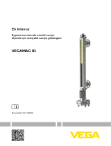 Vega VEGAMAG 81 Kullanma talimatları
-
 PowerWalker VFI 3000R LCD El kitabı
-
 Vega VEGAPULS 61 Kullanma talimatları
-
 Vega VEGAFLEX 86 Kullanma talimatları
-
 Vega VEGAFLEX 86 Kullanma talimatları
-
Xerox 5019/5021 Kullanici rehberi
-
 Vega VEGAFLEX 81 Kullanma talimatları
-
 Brooks 1358 Kullanma talimatları


