Hikoki C8FSHE Slide Compound Miter Saw Kullanma talimatları
- Kategori
- Elektrikli aletler
- Tip
- Kullanma talimatları

Slide Compound Miter Saw
Paneelsäge
º·ÏÙÛÔÎfiÙ˘-P¿vÙÈ¿Ï
Pilarka
Gérvágó
Pokosová pila
Raylı gönye kesme
Fierăstrău pentru tăieri înclinate
Potezna krožna žaga
TopáoÇoäÌaÓ ÔËÎa c ÔapaÎÎeÎëÌêÏË
ÌaÔpaÇÎÓïçÏÏË
Read through carefully and understand these instructions before use.
Diese Anleitung vor Benutzung des Werkzeugs sorgfältig durchlesen und verstehen.
¢È·‚¿ÛÙ ÚÔÛÂÎÙÈο Î·È Î·Ù·ÓÔ‹ÛÂÙ ·˘Ù¤˜ ÙȘ Ô‰ËÁ›Â˜ ÚÈÓ ÙË ¯Ú‹ÛË.
Przed użytkowaniem należy dokładnie przeczytać niniejszą instrukcję i zrozumieć jej treść.
Használat előtt olvassa el figyelmesen a használati utasítást.
Před použitím si pečlivě přečtěte tento návod a ujistěte se, že mu dobře rozumíte.
Aleti kullanmadan önce bu kılavuzu iyice okuyun ve talimatları anlayın.
Înainte de utilizare, citiţi cu atenţie și înţelegeţi prezentele instrucţiuni.
Pred uporabo natančno preberite in razumite ta navodila.
BÌËÏaÚeÎëÌo ÔpoäÚËÚe ÀaÌÌyï ËÌcÚpyÍáËï Ôo íÍcÔÎyaÚaáËË ÔpeÊÀe äeÏ ÔoÎëÁoÇaÚëcÓ ËÌcÚpyÏeÌÚoÏ.
Handling instructions
Bedienungsanleitung
√‰ËÁ›Â˜ ¯ÂÈÚÈÛÌÔ‡
Instrukcja obsługi
Kezelési utasítás
Návod k obsluze
Kullanım talimatları
Instrucţiuni de utilizare
Navodila za rokovanje
àÌcÚpyÍáËÓ Ôo íÍcÔÎyaÚaáËË
C 8FSHE • C 8FSE
C8FSHE
ÅÁ¿Åº¿Ä½ÉÅƔƑʺƔ
Č
ffi
ffi
Ě
ěč
ř ě
ě
č č
ğ
ğ
ş ğ
ş
ş
Ελληνικά ă
ΔΗΛΩΣΗ ΕΝΑΡΜΟΝΙΣΜΟΥ
Δηλώνουμε με αποκλειστική μας ευθύνη ότι οΦαλτσοκόπτης Ράντιαλ
οοποίος προσδιορίζεται από τον τύπο και ειδικό αναγνωριστικό κωδικό
είναι σύμφωνος με όλες τις σχετικές απαιτήσεις των Οδηγιών και
με τα σχετικά πρότυπα Τεχνικό Αρχείο στο Δείτε παρακάτω
Ο Διαχειριστής Ευρωπαϊκών Προτύπων στο γραφείο
εκπροσώπησης στην Ευρώπη είναι εξουσιοδοτημένος για τη
σύνταξη του τεχνικού φακέλου
Η δήλωση ισχύει μόνο για το προϊόν που είναι τοποθετημένη
σήμανση
Ţ
ă ă ă ă ă ă
ă ș ţ ș
șţ
ă ă
ţ ă
č
Ś
ś ł ą łą ą ść ż
ł ś ż
ż
ż ą
čč
č č
č
Русский
Ő
ő
ű
ű
ДЕКЛАРАЦИЯ СООТВЕТСТВИЯ
Мы с полной ответственностью заявляем что торцовочная пила
с параллельными направляющими идентифицируемая по типу
и соответствующему идентификационному коду отвечает
всем соответствующим требованиям директив и стандартов
Техническая документация в см ниже
Менеджер по европейским стандартам в представительстве в
Европе уполномочен составлять техническую документацию
Данная декларация относится к изделиям на которых имеется
маркировка
ffi
ffi
ffi

1
12
34
56
78
3
W
^
7
4
B
H
c
4
7
6
7
8
A
C
D
FG
H
I
J
K
L
B
5
9
M
1
2
4N
0
[
\
]
O
Q
5
U
V
W
XY
]
1
21
L
m
n n m
c
P
ÅÁ¿Åº¿Ä½ÉÅƔƑʺƔ
Č
ffi
ffi
Ě
ěč
ř ě
ě
č č
ğ
ğ
ş ğ
ş
ş
Ελληνικά ă
ΔΗΛΩΣΗ ΕΝΑΡΜΟΝΙΣΜΟΥ
Δηλώνουμε με αποκλειστική μας ευθύνη ότι οΦαλτσοκόπτης Ράντιαλ
οοποίος προσδιορίζεται από τον τύπο και ειδικό αναγνωριστικό κωδικό
είναι σύμφωνος με όλες τις σχετικές απαιτήσεις των Οδηγιών και
με τα σχετικά πρότυπα Τεχνικό Αρχείο στο Δείτε παρακάτω
Ο Διαχειριστής Ευρωπαϊκών Προτύπων στο γραφείο
εκπροσώπησης στην Ευρώπη είναι εξουσιοδοτημένος για τη
σύνταξη του τεχνικού φακέλου
Η δήλωση ισχύει μόνο για το προϊόν που είναι τοποθετημένη
σήμανση
Ţ
ă ă ă ă ă ă
ă ș ţ ș
șţ
ă ă
ţ ă
č
Ś
ś ł ą łą ą ść ż
ł ś ż
ż
ż ą
čč
č č
č
Русский
Ő
ő
ű
ű
ДЕКЛАРАЦИЯ СООТВЕТСТВИЯ
Мы с полной ответственностью заявляем что торцовочная пила
с параллельными направляющими идентифицируемая по типу
и соответствующему идентификационному коду отвечает
всем соответствующим требованиям директив и стандартов
Техническая документация в см ниже
Менеджер по европейским стандартам в представительстве в
Европе уполномочен составлять техническую документацию
Данная декларация относится к изделиям на которых имеется
маркировка
ffi
ffi
ffi

2
910
11 12
13
14 15
C
w
x\
C
w
x\
w
O
E
D
p
ov
u
at
q
s
R
w
ab
ab
ab
µµ
IndustrieZentrum NÖ –Süd, Straße 7, Obj. 58/A6 2355
Wiener Neudorf, Austria
Tel: +43 2236 64673/5
Fax: +43 2236 63373
URL: http://www.hikoki-powertools.at
1106 Bogáncsvirág u.5-7, Budapest, Hungary
Tel: +36 1 2643433
Fax: +36 1 2643429
URL: http://www.hikoki-powertools.hu
ul. Gierdziejewskiego 1
02-495 Warszawa, Poland
Tel: +48 22 863 33 78
Fax: +48 22 863 33 82
URL: http://www.hikoki-narzedzia.pl
Modřická 205, 664 48 Moravany, Czech Republic
Tel: +420 547 422 660
Fax: +420 547 213 588
URL: http://www.hikoki-powertools.cz
Kashirskoe Shosse 41, bldg. 2, 115409, Moscow, Russia
Tel: +7 495 727 4460
Fax: +7 495 727 4461
URL: http://www.hikoki-powertools.ru
Ring Road, No. 66, Mustang Traco Warehouses, Warehouse
No.1, Pantelimon City, 077145, Ilfov County, Romania
Tel: +40 371 135 109
Fax: +40 372 899 765
URL: http://www.hikoki-powertools.ro

3
910
ab
16 17
18 19
20 21
22 23
Z
7
0
Y
8
X
y
O
h
a
f
h
i
{
e
~
}
|
{
p
s
t
v
}~
å
e
e
g
f
i
j
k
l
b
d
s
T
J
z
I
G
F
IndustrieZentrum NÖ –Süd, Straße 7, Obj. 58/A6 2355
Wiener Neudorf, Austria
Tel: +43 2236 64673/5
Fax: +43 2236 63373
URL: http://www.hikoki-powertools.at
1106 Bogáncsvirág u.5-7, Budapest, Hungary
Tel: +36 1 2643433
Fax: +36 1 2643429
URL: http://www.hikoki-powertools.hu
ul. Gierdziejewskiego 1
02-495 Warszawa, Poland
Tel: +48 22 863 33 78
Fax: +48 22 863 33 82
URL: http://www.hikoki-narzedzia.pl
Modřická 205, 664 48 Moravany, Czech Republic
Tel: +420 547 422 660
Fax: +420 547 213 588
URL: http://www.hikoki-powertools.cz
Kashirskoe Shosse 41, bldg. 2, 115409, Moscow, Russia
Tel: +7 495 727 4460
Fax: +7 495 727 4461
URL: http://www.hikoki-powertools.ru
Ring Road, No. 66, Mustang Traco Warehouses, Warehouse
No.1, Pantelimon City, 077145, Ilfov County, Romania
Tel: +40 371 135 109
Fax: +40 372 899 765
URL: http://www.hikoki-powertools.ro

4
25
S
29
£
01
5 mm
12 mm
28
Q
¢
r
26
ç
S
M
†
LMM
†
B§
27
24
x
a
b

5
English Deutsch Ελληνικά
1Handle Griff
2Lock Lever Sperrhebel
3Motor Head Motorkopf
4Gear Case Getriebegehäuse
5Motor Motor
6Dust Bag Staubbeutel
7Hing Scharnier
8Holder (A) Halter (A)
9Light (Only C8FSHE) Licht (Nur C8FSHE)
0Indicator (For bevel scale) Zeiger (Für Schrägschnittskala)
ALaser Marker (Only C8FSHE) Lasermarkierer (Nur C8FSHE)
BSaw Blade Sägeblatt
CVise Assembly Schraubstocksatz
DFence (B) Gitter (B)
ESub Fence Hilfsführung
FLever Hebel Μλς
GSide Handle Seitengriff
HTurntable Drehbühne
ITable Insert Tischeinsatz
JIndicator (For miter scale) Zeiger (Für Gehrungsskala)
KFence (A) Gitter (A)
LLower Guard Unterer Schutz
MWasher (D) Unterlegscheibe (D)
NSpindle Cover Spindelabdeckung
OSwitch (For laser marker) Schalter (Für Lasermarkierer)
(Only C8FSHE) (Nur C8FSHE)
PTrigger Switch Auslöserschalter
QSwitch (For light) (Only C8FSHE) Lichtschalter (Nur C8FSHE)
RMaking (Pre-marked) Markierung (vormarkiert)
SSpindle Lock Spindelhebel
T6 mm Flat Head Screw 6 mm Flachkopfschraube
UGuard Schutz
VBase Grundplatte
WHolder Halter
XSet Pin Fixierstift
YClamp Lever Klemmhebel
Z6 mm Depth Adjustment Bolt 6 mm Tiefenstellschraube
[Slide Securing Knob Führungssicherungsknopf
\Adjuster (For laser marker) Einstellung (Für Lasermarkierer)
(Only C8FSHE) (Nur C8FSHE)
]Locking Pin Verriegelungsstift
`6 mm Bolt 6-mm-Schraube
aWorkpiece Werkstück
bAuxiliary Board Hilfsbrett
c8 mm Depth Adjustment Bolt 8-mm-Tiefeneinstellschraube
ερύλι
Μλς ασάλισης
Κεαλή Μτέρ
Θήκη Ταυτήτων
Μτέρ
Σακύλα Σκνης
Μεντεσές
Στήριγµα (A)
Λυνία (Μν στ C8FSHE)
∆είκτης (Για την κλίµακα κλίσης)
∆είκτης λέιερ
(Mvo yα τ C8FSHE)
Πρινωτή Λάµα
Συγκρτηµα Μέγγενης
δηγς (Β)
∆ευτερεύν δηγς
Πλευρικ ερύλι
Περιστρική Πλάκα
Τεµάι τρδσίας
∆είκτης (Για την κλίµακα λτµής)
δηγς (Α)
Κάτω πρυλακτήρας
Ρδέλα (D)
Κάλυµµα Άνα
∆ιακπτης (Για τ δείκτη λέιερ)
(Μν για τ C8FSHE)
Σκανδάλη ∆ιακπτης
∆ιακπτης (για τη λυνία) (Mvo
yα τ C8FSHE)
Σηµάδι (πρσηµειωµέν)
Ασάλεια Άνα
6 ιλ. Βίδα µε επίπεδη κεαλή
Πρυλακτήρας
Βάση
Στήριγµα
Περνη ρύθµισης
Μλς Σύσιης
6 ιλ. Μπυλνι ρύθµισης άθυς
Κυµπί αναστλής λίσθησης
Ρυθµιστής (Για τ δείκτη λέιερ)
(Mvo yα τ C8FSHE)
Περνη Ασαλείας
6 mm Μπυλνι
Αντικείµεν εργασίας
Βηθητικς πάγκς
Μπυλνι ρύθµισης άθυς 8 mm

6
English Deutsch Ελληνικά
d6 mm Nut 6 mm Schraubenmutter
e
6 mm Knob Bolt (Optional accessory)
Knopfschraube, 6 mm
(Sonderzubehör)
fHolder (Optional accessory) Halter (Sonderzubehör)
gSteel Square Stahlwinkel
h
6 mm Wing Nut (Optional accessory)
Flügelschraube, 6 mm
(Sonderzubehör)
iHeight Adjustment Bolt 6 mm Höheneinstellschraube, 6 mm
(Optional accessory) (Sonderzubehör)
jBase Surface Grundfläche
kStopper (Optional accessory) Anschlag (Sonderzubehör)
l
6 mm Knob Bolt (Optional accessory)
Knopfschraube, 6 mm
(Sonderzubehör)
mLine Linie
nWarning sign Warnzeichen
oScrew Holder Schraubenhalter
p6 mm Wing Bolt (B) 6-mm-Flügelschraube (B)
qVise Shaft Schraubstockachse
rLight lens Lichtlinse
sFence Gitter
t6 mm Wing Bolt (A) 6 mm-Flügelschraube (A)
uVise Plate Schraubstockbacke
vKnob Knopf
wLaser line Laserlinie
xGroove Nut
yBevel Scale Schrägschnittskala
zMiter Scale Gehrungsskala
Crown molding Vise Ass’y Schraubstocksatz für
{(Optional accessory) Kronenform (Sonderzubehör)
|
6 mm Wing Nut (Optional accessory)
Flügelmutter, 6 mm
(Sonderzubehör)
}Crown molding Stopper (L) Kronenformanschlag (L)
(Optional accessory) (Sonderzubehör)
~Crown molding Stopper (R) Kronenformanschlag (R)
(Optional accessory) (Sonderzubehör)
åCrown molding Kronenform
ç10 mm Box Wrench 10 mm Steckschüssel
†Bolt Schraube
¢Light Licht
£Wear limit line Verschleißgrenze
§Color (A) Farbe (A)
6 ιλ. παιµαδι
6 mm Φτερωτ µπυλνι
(Πραιρετικ εάρτηµα)
Στήριγµα (Πραιρετικ εάρτηµα)
Ατσαλένις Γνώµνας
6 mm Φτερωτ Παιµάδι
(Πραιρετικ εάρτηµα)
Μπυλνι Ρύθµισης Ύψυς
6 mm (Πραιρετικ εάρτηµα)
Επιάνεια Βάσης
Αναστλέας (Πραιρετικ εάρτηµα)
Μπυλνι-Κυµπί 6 mm
(Πραιρετικ εάρτηµα)
Γραµµή
Πρειδπιητικ σήµα
Στήριγµα Βίδας
6 mm Φτερωτ µπυλνι (Β)
Άνας µέγγενης
Φακς λυνίας
δηγς
6 mm Φτερωτ Μπυλνι (A)
Πλάκα Μέγγενης
Κυµπί
Γραµµή λέιερ
Αυλάκωση
Κλίµακα κλίσης
Κλίµακα Λτµής
Συγκρτηµα Μέγγενης για τη
∆ιαµρωση Κρνίας
(Πραιρετικ εάρτηµα)
6 mm Φτερωτ Παιµάδι
(Πραιρετικ εάρτηµα)
Αναστλέας ∆ιαµρωσης Κρνίας
(L) (Πραιρετικ εάρτηµα)
Αναστλέας ∆ιαµρωσης Κρνίας
(R) (Πραιρετικ εάρτηµα)
∆ιαµρωση Κρνίας
10 mm Κίλ Κλειδί
Μπυλνι
Λυνία
ρι θράς
ρώµα (Α)

7
Polski Magyar Čeština
1Rączka Markolat RukojeŅ
2Dźwignia blokady Rögzítőkar Blokovací páčka
3Głowica silnika Motorfej Hlava motoru
4Obudowa przekładni Hajtásház Převodová skříň
5Silnik Motor Motor
6Worek pyłowy Porzsák Sáček na prach
7Przegub Csuklós felfüggesztés Závěs
8Uchwyt (A) Tartó (A) Držák (A)
9Lampa (Tylko model C8FSHE)
Világítás (Csak a C8FSHE modell esetén)
Světlo (Pouze C8FSHE)
?Wskaźnik (Dla cięcia skośnego) Jelző (Ferde skála esetén) Indikátor (Pro stupnici úkosu)
AZnacznik laserowy (Tylko C8FSHE) Lézeres jelölő (Csak C8FSHE)
Laserový značkovač (Pouze C8FSHE)
BOstrze piły Fűrészlap Pilový kotouč
CImadło Satuszerelvény Sestava svěráku
DOgranicznik (B) Vezetőléc (B) Stavítko (B)
EPodogranicznik Alsó vezetőléc Menší stavítko
FDźwignia Kar Páčka
GRączka boczna Oldalsó markolat Boční rukojeŅ
HPodstawa obrotowa Forgatóasztal Otočný stůl
IWkładka stołowa Asztalbetét Vložka stolu
JWskaźnik Jelző Indikátor
(Dla skali uciosu) (Sarokillesztési skálához) (Pro stupnici pokosu)
KOgranicznik (A) Vezetőléc (A) Stavítko (A)
LOsłona dolna Alsó védőburkolat Spodní ochranný kryt
MPodkładka (D) Alátét (D) Podložka (D)
NPokrywa wrzeciona Tengelyfedél Kryt vřetena
OPrzełącznik (Dla znacznika Kapcsoló (Lézeres jelölőhöz) Vypínač (Pro laserový značkovač)
laserowego) (Tylko C8FSHE) (Csak C8FSHE) (Pouze C8FSHE)
PWyłącznik spustowy Indítókapcsoló Spouštěcí spínač
QWyłącznik (Lampy) Kapcsoló (Világítás) Vypínač (Světla) (Pouze C8FSHE)
(Tylko model C8FSHE) (Csak a C8FSHE modell esetén)
ROznakowanie Jelölés (előre megjelölt) Značka (předem vyznačeno)
(oznakowanie fabryczne)
SBlokada wrzeciona Tengelyrögzítő Blokování vřetena
TŚruba z łbem płaskim 6 mm 6 mm lapos fejű csavar
6 mm šroub s plochou zápustnou hlavou
UOsłona Védőlap Ochranný kryt
VPodstawa Alap Základová deska
WUchwyt Tartó Držák
XTrzpień ustalający Beállító csap Nastavovací kolík
YDźwignia zaciskowa Leszorító kar Páčka svorky
Z
Śruba regulacji głębokości 6 mm
6 mm-es mélységállító csavar
6 mm šroub k nastavení hloubky
[Pokrętło blokujące prowadnicy Csúszkarögzítő gomb ZajišŅovací knoflík posunu
\
Element regulacyjny (Znacznika laserowego)
Állító (Lézetkészítőhöz) Seřizovač (Pro laserový značkovač)
(Tylko C8FSHE) (Csak C8FSHE) (Pouze C8FSHE)
]Kołek blokujący Rögzítőcsapszeg Blokovací kolík
`Śruba 6 mm 6 mm csavar 6 mm šroub
aPrzedmiot obrabiany Munkadarab Obrobek
bPłyta pomocnicza Kiegészítő lap Pomocná deska
cŚruba regulacji głębokości 8 mm 8 mm-es mélységállító csavar 8 mm šroub nastavení hloubky

8
Polski Magyar Čeština
dNakrętka 6 mm 6 mm-es anya 6 mm matice
eŚruba skrzydełkowa 6 mm 6 mm-es szárnyascsavar 6 mm křídlový šroub
(Akcesorium opcjonalne) (Opcionális tartozék) (Doplňkové příslušenství)
fUchwyt (Akcesorium opcjonalne) Tartó (Opcionális tartozék) Držák (Doplňkové příslušenství)
gKątownik stalowy Acél négyzet Ocelový úhelník
hNakrętka motylkowa 6 mm 6 mm-es szárnyas anya 6 mm křídlový šroub
(Akcesorium opcjonalne) (Opcionális tartozék) (Doplňkové příslušenství)
iŚruba regulacji wysokości 6 mm Magasságállító csavar 6 mm Šroub pro nastavení výšky 6 mm
(Akcesorium opcjonalne) (Opcionális tartozék) (Doplňkové příslušenství)
jPowierzchnia podstawy Alapfelület Povrch základové desky
kOgranicznik (Akcesorium opcjonalne) Megállító (Opcionális tartozék) Zarážka (Doplňkové příslušenství)
lŚruba gałkowa 6 mm 6 mm-es gombos csavar 6 mm šroub s knoflíkem
(akcesorium opcjonalne) (opcionális tartozék) (doplňkové příslušenství)
mLinia Vonal Linka
nZnak ostrzegawczy Figyelmeztető búgás Varovný štítek
oUchwyt śruby Csavartartó Držák šroubu
pŚruba skrzydełkowa 6 mm (B) 6 mm szárnyas csavar (B) 6 mm Křídlový šroub (B)
qWał imadła Satutengely Hřídel svěráku
rSzkiełko lampy Fényforrás lencséje Čočka světla
sOgranicznik Vezetőléc Stavítko
tŚruba skrzydełkowa 6 mm (A) 6 mm szárnyas csavar (A) 6 mm křídlový šroub (A)
uTabliczka imadła Satutábla Deska svěráku
vGałka Gomb Knoflík
wLinia lasera Lézervonal Linie laseru
xRowek Horony Drážka
ySkala cięcia skosśnego Ferde skála Stupnice úkosu
zSkala uciosu Sarokillesztési skála (előre jelölt) Stupnice pokosu
{Imadło do form wypukłych Koronás öntvény satuszerelvény Svěrák zvonovnicového článku
(Akcesorium opcjonalne) (Opcionális tartozék) (Doplňkové příslušenství)
|Nakrętka motylkowa 6 mm 6 mm-es szárnyas anya 6 mm křídlový šroub
(Akcesorium opcjonalne) (Opcionális tartozék) (Doplňkové příslušenství)
}Ogranicznik do form wypukłych (L) Koronás öntvény megállító (L) Zarážka zvonovnicového článku (L)
(Akcesorium opcjonalne) (Opcionális tartozék) (Doplňkové příslušenství)
~Ogranicznik do form wypukłych (R) Koronás öntvény megállító (R) Zarážka zvonovnicového článku (R)
(Akcesorium opcjonalne) (Opcionális tartozék) (Doplňkové příslušenství)
åForma wypukła Koronás öntvény Zvonovnicový článek
çKlucz nasadowy 10 mm 10 mm-es dugókulcs 10 mm nástrčný klíč
†Śruba Csavar Šroub
¢Lampa Világítás Světlo
£Linia dopuszczalnego zużycia Kopási határvonal Čára limitu opotřebení
§Kolor (A) Szín (A) Barva (A)

9
Türkçe
1Sap
2Kilit kolu
3Motor Baßlıåı
4Dißli kutusu
5Motor
6Toz Torbası
7Menteße
8Tutamaç (A)
9Lamba (Sadece C8FSHE)
?Gösterge (Eåim ölçeåi için)
ALazer Óßaretleyici (Sadece C8FSHE)
BTestere bıçaåı
CMengene Takımı
DSiper (B)
EAlt Siper
FKol
GYan Sap
HDöner Taban
IMasa Eklemesi
JGösterge (Íev ölçeåine göre)
KSiper (A)
LAlt Koruyucu
MRondela (D)
NMil kapaåı
OAnahtar (Lazer ißaretleyici için)
(Sadece C8FSHE)
PAçma/Kapama Anahtarı
QDüåme (Lamba için)
(Sadece C8FSHE)
RÓßaretleme (ön-ißaretli)
SKilit iånesi
T6 mm düz Baßlı Vida
UKoruyucu
VTaban/Alt kısım
WTutamaç
XAyar pimi
YMengene kolu
Z6 mm derinlik Ayar Cıvatası
[Sürgü sıkıßtırma tokmaåı (A)
\Ayarlayıcı (Lazer ißaretleyici için)
(Sadece C8FSHE)
]Kilit Óånesi
`6 mm Cıvata
aÓß parçası
bYardımcı Levha
c8 mm'lik Derinlik ayarlama cıvatası
d6 mm Somun
Română
Mâner
Manetă de blocare
Capul motorului
Carcasa motorului
Motor
Sac pentru praf
Balama
Suport (A)
Lampă (Numai C8FSHE)
Indicator (Pentru gradaţia înclinării)
Marcator cu laser (Numai C8FSHE)
Lama fierăstrăului
Ansamblu menghină
Element de limitare (B)
Element de limitare inferior
Manetă
Mâner lateral
Suprafaţă de lucru pivotantă
Inserţie pentru suprafaţa de lucru
Indicator (Pentru scala pentru tăiere înclinată)
Element de protecţie (A)
Apărătoare inferioară
Șaibă (D)
Carcasa axului
Comutator (Pentru marcatorul
cu laser)
(Numai C8FSHE)
Comutator pentru pornire
Comutator (Pentru lampă)
(Numai C8FSHE)
Marcaj (pre-marcat)
Dispozitiv de blocare a axului
Șurub cu cap plat de 6 mm
Apărătoare
Placă de așezare
Suport
Ștaif de montaj
Manetă de prindere
Șurub de reglare pe adâncime de
6 mm
Mâner glisieră de fixare (A)
Reglator (Pentru contactul laserului)
(Numai C8FSHE)
Știft de blocare
Șurub de 6 mm
Piesă de prelucrat
Placă auxiliară
Bolţ de ajustare cu adâncime de 8 mm
Piuliţă de 6 mm
Slovenščina
Ročica
Blokirni vzvod
Glava motorja
Pogonsko ohišje
Motor
Vreča za prah
Tečaj
Nosilec (A)
Svetilka (Le C8FSHE)
Indikator (Za poševno merilo)
Laserski označevalec (Samo C8FSHE)
Rezilo žage
Sestav primeža
Ograja (B)
Stranska ograja
Ročica
Stranska ročica
Obračalna miza
Ploščni vstavek
Indikator (A) (Za zajerno merilo)
Ograja (A)
Spodnje varovalo
Tesnilo (D)
Pokrov gredi
Stikalo (Za laserski N
označevalec) (Samo C8FSHE)
Sprožilno stikalo
Stikalo (Za svetilko)
(Samo C8FSHE)
Označevanje (predoznačeno)
Zaklep gred
Vijak z ugreznjeno glavo 6 mm
Varovalo
Podlaga
Nosilec
Nastavitveni zatič
Ročica objemke
Vijak za nastavitev globine
6 mm
Gumb za zavarovanje pomika (A)
Nastavljalec (Za laserski ozna
č
evalec)
(Samo C8FSHE)
Zaklepni zatič
6 mm sornik
Obdelovalni kos
Dodatna ploΙηa
8 mm vijak za nastavitev globine
Matica 6 mm

10
Română
Șurub de 6 mm cu cap fluture
(Accesoriu opţional)
Suport
(Accesoriu opţional)
Echer din oţel
Piuliţă fluture de 6 mm
(Accesoriu opţional)
Șurub de 6 mm pentru reglarea
înălţimii (accesoriu opţional)
Suprafaţa plăcii de așezare
Opritor
(Accesoriu opţional))
Bolţ de 6 mm mâner
(accesoriu opţional)
Linie
Semn de avertizare
Suport pentru șuruburi
Șurub de 6 mm cu cap fluture (B)
Arborele menghinei
Lentila lămpii
Ghidaj
Șurub de 6 mm cu cap fluture (A)
Placa menghinei
Buton
Linie laser
Canelură
Gradaţia înclinării
Scală înclinată
Ansamblul dispozitivului pivotant
de deplasare al menghinei
(Accesoriu opţional)
Piuliţă fluture de 6 mm
(Accesoriu opţional)
Opritorul dispozitivului pivotant de
deplasare (L) (Accesoriu opţional)
Opritorul dispozitivului pivotant de
deplasare (R) (Accesoriu opţional)
Dispozitiv pivotant de deplasare
Cheie inelară de 10 mm
Șurub
Lampă
Linie limită pentru uzură
Culoare (A)
Slovenščina
6 mm sornik s krilci
(opcijski dodatek)
Nosilec
(Opcijski dodatek)
Jeklen kvadrat
6 mm matica s krilci
(Opcijski dodatek)
6 mm sornik za nastavljanje višine
(Opcijski dodatek)
Površina podlage
Zaustavljalo
(Opcijski dodatek)
6 mm sornik s krilci
(opcijski dodatek)
Linija
Opozorilni simbol
Nosilec vijaka
6 mm sornik s krilci (B)
Gred primeža
Leča svetilke
Ograja
6 mm sornik s krilci (A)
Plošča primeža
Gumb
Laserska linija
Utor
Poševno merilo
Zajerno merilo
Primež kronaste oblike
(Opcijski dodatek)
6 mm matica s krilci
(Opcijski dodatek)
Omejevalnik kronaste oblike (L)
(Opcijski dodatek)
Omejevalnik kronaste oblike (R)
(Opcijski dodatek)
Kronasta oblika
10 mm ključ
Sornik
Svetilka
Omejevalna linija obrabe
Barva (A)
Türkçe
e6 mm Kelebek Cıvata
(Ósteåe baålı gelen aksesuar)
fTutamaç
(Ósteåe baålı gelen aksesuar)
gÇelik Kare
h6 mm Kelebek Cıvata
(Ósteåe baålı gelen aksesuar)
iYükseklik Ayar Cıvatası 6 mm
(Ósteåe baålı gelen aksesuar)
jTaban Yüzey
kDurdurucu
(Ósteåe baålı gelen aksesuar)
l6 mm'lik Tokmak cıvata
(Ósteåe baålı aksesuar)
mÇizgi
nUyarı ißareti
oVida Tutamacı
p6 mm Kelebek Cıvata (B)
qMengene Mili
rLamba merceåi
sSiper
t6 mm Kelebek Cıvata (A)
uMengene Tabanı
vKontrol Düåmesi
wLazer çizgisi
xOluk
yEåim ölçeåi
zÍev Ölçeåi
{Taç Kalıp Mengene Takımı
(Ósteåe baålı gelen aksesuar)
|6 mm Kelebek Cıvata
(Ósteåe baålı gelen aksesuar)
}Taç Kalıp Durdurucu (L)
(Ósteåe baålı gelen aksesuar)
~Taç Kalıp Durdurucu (R)
(Ósteåe baålı gelen aksesuar)
åTaç kalıp
ç10 mm Lokma Anahtarı
†Cıvata
¢Lamba
£Yıpranma limiti çizgisi
§Renk (A)

11
PyccÍËÈ
1PyÍoÓÚÍa
2
ÅÎoÍËpoÇoäÌêÈ pêäaÖ
3ÉoÎoÇÍa ÀÇËÖaÚeÎÓ
4KopÔyc ÔpËÇoÀa
5MoÚop
6èêÎecÄopÌËÍ
7èeÚÎÓ
8îËÍcaÚop (A)
9ãaÁep (ÚoÎëÍo C8FSHE)
0àÌÀËÍaÚop (ÑÎÓ åÍaÎê
ÌaÍÎoÌa)
AãaÁepÌêÈ yÍaÁaÚeÎë (ToÎëÍo
C8FSHE)
BèoÎoÚÌo ÔËÎê
CìÁeÎ ÚËcÍoÇ
DOÖpaÊÀeÌËe (B)
E
BcÔoÏoÖaÚeÎëÌoe oÖpaÊÀeÌËe
FPêäaÖ
GÅoÍoÇaÓ pyÍoÓÚÍa
HèoÇopoÚÌêÈ cÚoÎ
IBcÚaÇÍa cÚoÎa
JàÌÀËÍaÚop (ÑÎÓ åÍaÎê
peÁaÌËÓ ÔpË ÔoÇopoÚe)
KOÖpaÊÀeÌËe (A)
LHËÊÌee ÔpeÀoxpaÌËÚeÎëÌoe
ÔpËcÔocoÄÎeÌËe
MèpoÏêÇaÚeÎë (D)
NóexoÎ åÔËÌÀeÎÓ
OèepeÍÎïäaÚeÎë (ÑÎÓ ÎaÁepÌoÖo
yÍaÁaÚeÎÓ) (ToÎëÍo C8FSHE)
PèycÍoÇoÈ ÔepeÍÎïäaÚeÎë
QèepeÍÎïäaÚeÎë (ÑÎÓ ÎaÁepa)
(ToÎëÍo C8FSHE)
RMapÍËpoÇÍa (ÔpeÀÇapËÚeÎëÌo
ÔpocÚaÇÎeÌÌaÓ)
SÂaçeÎÍa åÔËÌÀeÎÓ
T6 ÏÏ ÇËÌÚ c ÔÎocÍoÈ ÖoÎoÇÍoÈ
UèpeÀoxpaÌËÚeÎëÌoe ycÚpoÈcÚÇo
VOcÌoÇaÌËe
WîËÍcaÚop
PyccÍËÈ
XìcÚaÌoÇoäÌêÈ åÚËÙÚ
Y3aÊ
Ë
Ì
o
È pêya
Ö
Z6 ÏÏ ÇËÌÚ c ÔÎocÍoÈ ÖoÎoÇÍoÈ
[PyÍoÓÚÍa ÙËÍcËpoÇaÌËÓ
cÍoÎëÊeÌËÓ (A)
\
PeÖyÎÓÚop (ÀÎÓ ÎaÁepÌoÖo ÏapÍepa)
(ToÎëÍo C8FSHE)
]CÚoÔopÌaÓ åÔËÎëÍa
`6 ÏÏ ÄoÎÚ
aÂaÖoÚoÇÍa
bÑoÔoÎÌËÚeÎëÌêÈ ÔyÎëÚ
c8-ÏËÎÎËÏeÚpoÇêÈ ÄoÎÚ
peÖyÎËpoÇaÌËÓ ÖÎyÄËÌê
d6 ÏÏ ÉaÈÍa
e
6 ÏÏ ÄapaåÍoÇêÈ ÄoÎÚ
(ÀoÔoÎÌËÚeÎëÌaÓ ÔpËÌaÀÎeÊÌocÚë)
fîËÍcaÚop (ÀoÔoÎÌËÚeÎëÌaÓ
ÔpËÌaÀÎeÊÌocÚë)
gCÚaÎëÌoÈ yÖoÎëÌËÍ
h6 ÏÏ ÄapaåÍoÇaÓ ÖaÈÍa
(ÀoÔoÎÌËÚeÎëÌaÓ ÔpËÌaÀÎeÊÌocÚë)
i6 ÏÏ ÄoÎÚ peÖyÎËpoÇÍË ÇêcoÚê
(ÀoÔoÎÌËÚeÎëÌaÓ ÔpËÌaÀÎeÊÌocÚë)
jOÔopÌaÓ ÔoÇepxÌocÚë
kCÚoÔop (ÀoÔoÎÌËÚeÎëÌaÓ
ÔpËÌaÀÎeÊÌocÚë)
l
6-ÏËÎÎËÏeÚpoÇêÈ cÚoÔopÌêÈ
ÄoÎÚ (ÀoÔoÎÌËÚeÎëÌaÓ
ÔpËÌaÀÎeÊÌocÚë)
mãËÌËÓ
nèpeÀyÔpeÊÀaïçËÈ ÁÌaÍ
oBËÌÚoÇoÈ ÙËÍcaÚop
p6 ÏÏ ÅapaåÍoÇêÈ ÄoÎÚ (B)
qBaÎ ÚËcÍoÇ
rãËÌÁa ÎaÁepa
sãËÌeÈÍa
t6 ÏÏ ÄapaåÍoÇêÈ ÄoÎÚ (A)
uèÎacÚËÌa ÚËcÍoÇ
vPyÍoÓÚÍa
wãËÌËÓ ÎaÁepa
xèaÁ
yòÍaÎa ÌaÍÎoÌa
zòÍaÎa peÁaÌËÓ ÔpË ÔoÇopoÚe
PyccÍËÈ
{
ìÁeÎ ÚËcÍoÇ oÔpeccoÇÍË ÇeÌáa
(ÀoÔoÎÌËÚeÎëÌaÓ ÔpËÌaÀÎeÊÌocÚë)
|6 ÏÏ ÄapaåÍoÇaÓ ÖaÈÍa
(ÀoÔoÎÌËÚeÎëÌaÓ ÔpËÌaÀÎeÊÌocÚë)
}
CÚoÔop oÔpeccoÇÍË ÇeÌáa (L)
(ÀoÔoÎÌËÚeÎëÌaÓ ÔpËÌaÀÎeÊÌocÚë)
~
CÚoÔop oÔpeccoÇÍË ÇeÌáa (R)
(ÀoÔoÎÌËÚeÎëÌaÓ ÔpËÌaÀÎeÊÌocÚë)
åOÔpeccoÇÍa ÇeÌáa
ç10 ÏÏ ÌaÍËÀÌoÈ ÍÎïä
†ÅoÎÚ
¢ãaÁep
£ãËÌËÓ ÔpeÀeÎëÌoÖo ËÁÌoca
§ñÇeÚ (A)

12
Symbols
The following show
symbols used for the
machine. Be sure that
you understand their
meaning before use.
Symbole
Die folgenden Symbole
werden für diese
Maschine verwendet.
Achten Sie darauf, diese
vor der Verwendung zu
verstehen.
™‡Ì‚ÔÏ·
Τα παρακάτω δείνυν τα
σύµλα πυ
ρησιµπιύνται στ
µηάνηµα. Βεαιωθείτε τι
κατανείτε τη σηµασίας
τυς πριν τη ρήση.
Symbole
Następujące oznaczenia
to symbole używane w
instrukcji obsługi
maszyny. Upewnij się, że
rozumiesz ich znaczenie
zanim użyjesz narzędzia.
Read instruction
manual.
Bedienungsanleitung
lesen.
∆ιαάστε τ
εγειρίδι δηγιών. Przeczytaj instrukcje.
Always wear eye
protection.
Tragen Sie immer
einen Augenschutz.
Φράτε πάντα τν
κατάλληλ επλισµ
για την πρστασία
των µατιών.
Zawsze nosić okulary
ochronne.
Přečtěte si návod.
Vždy noste ochranu
očí.
Kullanım kılavuzunu
okuyun.
Daima koruyucu
gözlük takın.
èpoäÚËÚe
pyÍoÇoÀcÚÇo Ôo
íÍcÔÎyaÚaáËË.
BceÖÀa ÌaÀeÇaÈÚe
cpeÀcÚÇa ÁaçËÚê
ÖÎaÁ.
Symboly
Následující text obsahuje
symboly, které jsou použity
na zařízení. Ujistěte se, že
rozumíte jejich obsahu
před tím, než začnete
zařízení používat.
Simgeler
Aßaåıda, bu alet için kullanılan
simgeler gösterilmißtir. Aleti
kullanmadan önce bu
simgelerin ne anlama geldiåini
anladıåınızdan emin olun.
CËÏÇoÎê
HËÊe ÔpËÇeÀeÌê cËÏÇoÎê,
ËcÔoÎëÁyeÏêe ÀÎÓ
ÏaåËÌê. èepeÀ ÌaäaÎoÏ
paÄoÚê oÄÓÁaÚeÎëÌo
yÄeÀËÚecë Ç ÚoÏ, äÚo Bê
ÔoÌËÏaeÚe Ëx ÁÌaäeÌËe.
Only for EU countries
Do not dispose of electric
tools together with
household waste material!
In observance of European
Directive 2002/96/EC on
waste electrical and
electronic equipment and
its implementation in
accordance with national
law, electric tools that have
reached the end of their life
must be collected
separately and returned to
an environmentally
compatible recycling
facility.
Nur für EU-Länder
Werfen Sie
Elektrowerkzeuge nicht
in den Hausmüll!
Gemäss Europäischer
Richtlinie 2002/96/EG
über Elektro- und
Elektronik- Altgeräte
und Umsetzung in
nationales Recht
müssen verbrauchte
Elektrowerkzeuge
getrennt gesammelt
und einer
umweltgerechten
Wiederververtung
zugeführt werden.
Mvo για τις ώρες της
EE
Mηv πετάτε τα ηλεκτρικά
εργαλεία στov κάδo
oικιακώv απoρριµµάτωv!
Σύµωvα µε τηv
εuρωπαϊκή oδηγία 2002/
96/EK περί ηλεκτρικώv και
ηλεκτρovικώv σuσκεuώv
και τηv εvσωµάτωσή της
στo εθvικ δίκαιo, τα
ηλεκτρικά εργαλεία
πρέπει vα σuλλέγovται
εωριστά και vα
επιστρέovται για
αvακύκλωση µε τρπo
ιλικ πρoς τo
περιάλλov.
Dotyczy tylko państw UE
Nie wyrzucaj
elektronarzędzi wraz z
odpadami z
gospodarstwa
domowego!
Zgodnie z Europejską
Dyrektywą 2002/96/WE w
sprawie zużytego sprzętu
elektrotechnicznego i
elektronicznego oraz
dostosowaniem jej do
prawa krajowego, zużyte
elektronarzędzia należy
posegregować i
zutylizować w sposób
przyjazny dla środowiska.
Jen pro státy EU
Elektrické nářadí
nevyhazujte do
komunálního odpadu!
Podle evropské
směrnice 2002/96/EG o
nakládání s použitými
elektrickými a
elektronickými
zařízeními a
odpovídajících
ustanovení právních
předpisů jednotlivých
zemí se použitá
elektrická nářadí musí
sbírat odděleně od
ostatního odpadu a
podrobit ekologicky
šetrnému recyklování.
Sadece AB ülkeleri için
Elektrikli el aletlerini
evdeki çöp kutusuna
atmayınız!
Kullanılmıß elektrikli
aletleri, elektrik ve
elektronikli eski
cihazlar hakkındaki
2002/96/EC Avrupa
yönergelerine göre ve
bu yönergeler ulusal
hukuk kurallarına göre
uyarlanarak, ayrı
olarak toplanmalı ve
çevre ßartlarına uygun
bir ßekilde tekrar
deåerlendirmeye
gönderilmelidir.
ToÎëÍo ÀÎÓ cÚpaÌ EC
He ÇêÍËÀêÇaÈÚe
íÎeÍÚpoÔpËÄopê ÇÏecÚe
c oÄoêäÌêÏ ÏycopoÏ!
B cooÚÇeÚcÚÇËË c
eÇpoÔeÈcÍoÈ
ÀËpeÍÚËÇoÈ 2002/96/EG
oÄ yÚËÎËÁaáËË cÚapêx
íÎeÍÚpËäecÍËx Ë
íÎeÍÚpoÌÌêx ÔpËÄopoÇ
Ë Ç cooÚÇeÚcÚÇËË c
ÏecÚÌêÏË ÁaÍoÌaÏË
íÎeÍÚpoÔpËÄopê,
ÄêÇçËe Ç
íÍcÔÎyaÚaáËË, ÀoÎÊÌê
yÚËÎËÁoÇêÇaÚëcÓ
oÚÀeÎëÌo ÄeÁoÔacÌêÏ
ÀÎÓ oÍpyÊaïçeÈ cpeÀê
cÔocoÄoÏ.
Jelölések
Az alábbiakban a géphez
alkalmazott jelölések
vannak felsorolva. A gép
használata előtt feltétlenül
ismerje meg ezeket a
jelöléseket.
Mindig viseljen
védőszemüveget.
Csak EU-országok
számára
Az elektromos
kéziszerszámokat ne
dobja a háztartási
szemétbe!
A használt villamos és
elektronikai
készülékekről szóló
2002/96/EK irányelv és
annak a nemzeti jogba
való átültetése szerint
az elhasznált
elektromos
kéziszerszámokat
külön kell gyűjteni, és
környezetbarát módon
újra kell hasznosítani.
Olvassa el a
Használati utasítást.
Preberite navodila za
uporabo.
Uporaba zaščite za
oči je obvezna.
Simboli
V nadaljevanju so
prikazani simboli,
uporabljeni pri stroju.
Pred uporabo se
prepričajte, da jih
razumete.
Samo za države EU
Električnih orodij ne
zavržite skupaj z
gospodinjskimi
odpadki!
V skladu z evropsko
direktivo 2002/96/EC
o odpadni električni in
elektronski opremi in
izvedbi v skladu z
državnimi zakoni, je
treba električna
orodja, ki so dosegla
življenjsko dobo
ločeno zbirati in vrniti
v z okoljem združljivo
ustanovo za
recikliranje.
Citiţi manualul de
instrucţiuni.
Purtaţi întotdeauna
protecţie pentru ochi.
Simboluri
În cele ce urmează sunt
prezentate simbolurile
folosite pentru mașină.
Înainte de utilizare,
asiguraţi-vă că înţelegeţi
semnificaţia acestora.
Numai pentru ţările membre
UE
Nu aruncaţi această sculă
electrică împreună cu
deșeurile menajere!
În conformitate cu Directiva
Europeană 2002/96/CE
referitoare la deșeurile
reprezentând echipamente
electrice și electronice și la
implementarea acesteia în
conformitate cu legislaţiile
naţionale, sculele electrice
care au ajuns la finalul
duratei de folosire trebuie
colectate separat și duse la o
unitate de reciclare
compatibilă cu mediul
înconjurător.
Always wear
hearing protection.
Stets Gehörschutz
tragen.
Φράτε πάντα
πρστατευτικά
ακής.
Zawsze nosić
słuchawki ochronne.
Mindig viseljen a
hallást védő
védőfelszerelést.
Vždy používejte
chrániče sluchu. Daima koruyucu
kulaklık takın.
BceÖÀa ÌaÀeÇaÈÚe
cpeÀcÚÇa ÁaçËÚê
opÖaÌoÇ cÎyxa.
Purtaţi întotdeauna
protecţie auditivă. Obvezna je uporaba
zaščite za ušesa.

13
English
GENERAL OPERATIONAL PRECAUTIONS
WARNING! When using electric tools, basic safety precautions should always be
followed to reduce the risk of fire, electric shock and personal injury, including
the following.
Read all these instructions before operating this product and save these
instructions.
For safe operations:
1. Keep work area clean. Cluttered areas and benches invite injuries.
2. Consider work area environment. Do not expose power tools to rain. Do
not use power tools in damp or wet locations. Keep work area well lit.
Do not use power tools where there is risk to cause fire or explosion.
3. Guard against electric shock. Avoid body contact with earthed or grounded
surfaces (e.g. pipes, radiators, ranges, refrigerators).
4. Keep children and infirm persons away. Do not let visitors touch the tool
or extension cord. All visitors should be kept away from work area.
5. Store idle tools. When not in use, tools should be stored in a dry, high or
locked up place, out of reach of children and infirm persons.
6. Do not force the tool. It will do the job better and safer at the rate for
which it was intended.
7. Use the right tool. Do not force small tools or attachments to do the job of
a heavy duty tool. Do not use tools for purposes not intended; for example,
do not use circular saw to cut tree limbs or logs.
8. Dress properly. Do not wear loose clothing or jewelry, they can be caught
in moving parts. Rubber gloves and non-skid footwear are recommended
when working outdoors. Wear protecting hair covering to contain long
hair.
9. Use eye protection. Also use face or dust mask if the cutting operation is
dusty.
10. Connect dust extraction equipment.
Cutting operation by this compound saw may produce considerable
amount of dust from extraction duct on fixed guard.
(Dust material: Wood or Aluminium)
If devices are provided for the connection of dust extraction and collection
facilities ensure these are connected and properly used.
11. Do not abuse the cord. Never carry the tool by the cord or yank it to
disconnect it from the receptacle. Keep the cord away from heat, oil and
sharp edges.
12. Secure work. Use clamps or a vise to hold the work. It is safer than using
your hand and it frees both hands to operate tool.
13. Do not overreach. Keep proper footing and balance at all times.
14. Maintain tools with care. Keep cutting tools sharp and clean for better
and safer performance. Follow instructions for lubrication and changing
accessories. Inspect tool cords periodically and if damaged, have it repaired
by authorized service center. Inspect extension cords periodically and
replace, if damaged. Keep handles dry, clean, and free from oil and grease.
15. Disconnect tools. When not in use, before servicing, and when changing
accessories such as blades, bits and cutters.
16. Remove adjusting keys and wrenches. Form the habit of checking to see
that keys and adjusting wrenches are removed from the tool before turning
it on.
17. Avoid unintentional starting. Do not carry a plugged-in tool with a finger
on the switch. Ensure switch is off when plugging in.
18. Use outdoor extension leads. When tool is used outdoors, use only
extension cords intended for outdoor use.
19. Stay alert. Watch what you are doing. Use common sense. Do not operate
tool when you are tired.
20. Check damaged parts. Before further use of the tool, a guard or other part
that is damaged should be carefully checked to determine that it will
operate properly and perform its intended function. Check for alignment
of moving parts, free running of moving parts, breakage of parts, mounting
and any other conditions that may affect its operation. A guard or other
part that is damaged should be properly repaired or replaced by an
authorized service center unless otherwise indicated in this handling
instructions. Have defective switches replaced by an authorized service
center. Do not use the tool if the switch does not turn it on and off.
21. Warning
The use of any accessory or attachment, other than those recommended
in this handling instructions, may present a risk of personal injury.
22. Have your tool repaired by a qualified person.
This electric tool is in accordance with the relevant safety requirements.
Repairs should only be carried out by qualified persons using original
spare parts. Otherwise this may result in considerable danger to the user.
PRECAUTIONS ON USING SLIDE COMPOUND
MITER SAW
1. Keep the floor area around the machine level. Well maintained and free of
loose materials e.g. chips and cut-offs.
2. Provide adequate general or localized lighting.
3. Do not use power tools for applications other than those specified in the
handling instructions.
4. Repairing must be done only by authorized service facility. Manufacturer
is not responsible for any damages and injuries due to the repair by the
unauthorized persons as well as the mishandling of the tool.
5. To ensure the designed operational integrity of power tools, do not remove
installed covers or screws.
6. Do not touch movable parts or accessories unless the power source has
been disconnected.
7. Use your tool at lower input than specified on the nameplate; otherwise,
the finish may be spoiled and working efficiency reduced due to motor
overload.
8. Do not wipe plastic parts with solvent. Solvents such as gasoline, thinner,
benzine, carbon tetrachloride, alcohol, may damage and crack plastic parts.
Do not wipe them with such solvent. Clean plastic parts with a soft cloth
lightly dampened with soapy water.
9. Use only original HiKOKI replacement parts.
10. This tool should only be disassembled for replacement of carbon brushes.
11. The exploded assembly drawing on this handling instructions should be
used only for authorized service facility.
12. Never cut ferrous metals or masonry.
13. Adequate general or localized lighting is provided. Stock and finished
workpieces are located close to the operators normal working position.
14. Wear suitable personal protective equipment when necessary, this could
include:
Hearing protection to reduce the risk of induced hearing loss.
Eye protection to reduce the risk of injuring an eye.
Respiratory protection to reduce the risk of inhalation of harmful dust.
Gloves for handling saw blades (saw blades shall be carried in a holder
wherever practicable) and rough material.
15. The operator is adequately trained in the use, adjustment and operation
of the machine.
16. Refrain from removing any cut-offs or other parts of the workpiece from
the cutting area whilst the machine is running and the saw head is not in
the rest position.
17. Never use the slide compound miter saw with its lower guard locked in
the open position.
18. Ensure that the lower guard moves smoothly.
19. Do not use the saw without guards in position, in good working order and
properly maintained.
20. Use correctly sharpened saw blades. Observe the maximum speed marked
on the saw blade.
21. Do not use saw blades which are damaged or deformed.
22. Do not use saw blades manufactured from high speed steel.
23. Use only saw blades recommended by HiKOKI.
Use of saw blade comply with EN847-1.
24. The saw blades should be 216 mm external diameter.
25. Select the correct saw blade for the material to be cut.
26. Never operate the slide compound miter saw with the saw blade turned
upward or to the side.
27. Ensure that the workpiece is free of foreign matter such as nails.
28. Replace the table insert when worn.
29. Do not use the saw to cut other than aluminium, wood or similar materials.
30. Do not use the saw to cut other materials than those recommended by
the manufacturer.
31. Blade replacement procedure, including the method for repositioning and
a warning that this must be carried out correctly.
32. Connect the slide compound miter saw to a dust collecting device when
sawing wood.
33. Take care when slotting.
34. When transporting or carrying the tool, do not grasp the holder. Grasp
the handle instead of the holder.
35. Start cutting only after motor revolution reaches maximum speed.
36. Promptly cut OFF the switch when abnormality observed.
37. Shut off power and wait for saw blade to stop before servicing or adjusting
tool.
38. During a miter or bevel cut the blade should not be lifted until it has stopped
rotation completely.

14
English
39. During slide cutting operation, the saw must be pushed and slided away
from the operator.
40. Take all the possibility of residual risks in cutting operation into your
consideration, such as the laser radiation to your eyes, the inadvertent
access to moving parts on slide mechanical parts on machine and so on.
SPECIFICATIONS
0° 65 mm × 312 mm
**75 mm × 262 mm with aux. board (30 mm)
Miter 45° 65 mm × 220 mm
**75 mm × 185 mm with aux. board (20 mm)
Left 45° 45 mm × 312 mm
**50 mm × 252 mm with aux. board (30 mm)
Bevel
Right 5° 60 mm × 312 mm
**70 mm × 252 mm with aux. board (30 mm)
Bevel (Left) 45° + Miter 45°
45 mm × 220 mm
Compound **50 mm × 170 mm with aux. board (30 mm)
Bevel (Right) 5° + Miter 45° 60 mm × 220 mm
**70 mm × 170 mm with aux. board (30 mm)
Saw Blade Dimensions (oD × iD × Thickness) 216 mm × 30 mm × 2 mm
Miter Cutting Angle Right 0° – 57°, Left 0° – 45°
Bevel Cutting Angle Right 0° – 5°, Left 0° – 48°
Compound Cutting Angle Bevel (Left) 0° – 45° Miter (Right and Left) 0° – 45°
Bevel (Right) 0° – 5°
Voltage (by areas)* (110 V, 230 V)
Power Input* 1050 W
No-Load Speed 5500 min–1
Machine Dimensions (Width × Depth × Height) 555 mm × 790 mm × 485 mm
Weight (Net) 15 kg (C8FSHE) / 14 kg (C8FSE)
Maximum output Po<3 mW Class Laser Product
(Iambda) 654 nm
Laser medium Laser Diode
Max. Cutting
Capacity
Height × Width
Laser Marker
(Only Model C8FSHE)
* Be sure to check the nameplate on product as it is subject to change by areas.
When cutting the workpiece which has the dimension of “**” there might be some possibility of the lower end of the circular saw to touch with the workpiece, even if
the motor head is located at the lower limit position. Pay attention when cutting the workpiece. For further details, refer to “PRACTICAL APPLICATIONS”. Mount the
auxiliary board on the fence surface (Refer ( ) the thickness of auxiliary board). Refer to "12. Cutting large workpieces" (Fig. 16).
STANDARD ACCESSORIES
(1) 216 mm TCT Saw blade (mounted on tool) .................................................. 1
(2) Dust bag ........................................................................................................... 1
(3) 10 mm Box wrench ......................................................................................... 1
(4) Vise Assembly ................................................................................................. 1
(5) Holder ............................................................................................................... 1
(6) Side Handle ...................................................................................................... 1
Standard accessories are subject to change without notice.
OPTIONAL ACCESSORIES (SOLD SEPARATELY)
(1) Extension Holder and Stopper
(2) Saw blade 216 mm TCT Saw blade (Total teeth: 60)
(3) Crown molding Vise Ass'y (Include Crown molding Stopper (L))
(4) Crown molding Stopper (L)
(5) Crown molding Stopper (R)
(6) Sub Fence
Optional accessories are subject to change without notice.
APPLICATION
䡬
Cutting various types of aluminium sash and wood.
UNPACKING
䡬
Carefully unpack the power tool and all related items (standard accessories).
䡬
Check carefully to make certain all related items (standard accessories) are
present.
PRIOR TO OPERATION
1. Power source
Ensure that the power source to be utilized conforms to the power
requirements specified on the product nameplate.
2. Power switch
Ensure that the power switch is in the OFF position. If the plug is connected
to a receptacle while the trigger switch is in the ON position, the power tool
will start operating immediately, inviting serious accident.

15
English
3. Extention cord
When the work area is removed from the power source, use an extension
cord of sufficient thickness and rated capacity. The extension cord should be
kept as short as practicable.
4. When the power tool is prepared for shipping, its main parts are secured by
a locking pin
Move the handle slightly so that the locking pin can be disengaged.
During transport, lock the locking pin into the gear case (Fig. 4).
5. Attach the dust bag to the main unit (Fig. 1)
6. Installation
Ensure that the machine is always fixed to bench.
Attach the power tool to a level, horizontal work bench.
Select 8 mm diameter bolts suitable in length for the thickness of the work
bench.
Bolt length should be at least 25 mm plus the thickness of the work bench.
For example, use 8 mm × 65 mm bolts for a 25 mm thick work bench.
ADJUSTING THE POWER TOOL PRIOR TO USE
CAUTION
Make all necessary adjustments before inserting the plug in the power source.
1. Check to see that the lower guard operates smoothly
CAUTION
䡬
This slide compound miter saw is equipped with a saw head lock as safety
device.
䡬
To lower the saw head to cut, the lock must be released by pressing the lock
lever with your thumb.
(1) When you push down the handle while pushing the lock lever, check that
the lower guard revolves smoothly (Fig. 5).
(2) Next, check that the lower guard returns to the original position when the
handle is raised.
2. Checking the saw blade lower limit position (Fig. 6 and Fig. 7)
Check that the saw blade can be lowered 10 mm to 11 mm below the table
insert.
When you replace a saw blade with a new one, adjust the lower limit position
so that the saw blade will not cut the turntable or complete cutting cannot
be done.
To adjust the lower limit position of the saw blade, follow the procedure (1)
indicated below. (Fig. 7)
Furthermore, when changing the position of a 8 mm depth adjustment bolt
that serves as a lower limit position stopper of the saw blade.
(1) Turn the 8 mm depth adjustment bolt, change the height where the bolt
head and the hinge contacts, and adjust the lower limit position of the saw
blade.
NOTE
Confirm that the saw blade is adjusted so that it will not cut into the turntable.
3. Lower limit position of saw blade when cutting a large workpiece
NOTE
When cutting a workpiece exceeding 65 mm in height in right-angle cutting
or 60 mm in left bevel angle cutting or 45 mm in right bevel angle cutting,
adjust the lower limit position so that the base of the motor head (Fig. 6) will
not come in contact with the workpiece.
PRACTICAL APPLICATIONS
WARNING
䡬
To avoid personal injury, never remove or place a workpiece on the table
while the tool is being operated.
䡬
Never place your limbs inside of the line next to warning sign while the tool
is being operated. This may cause hazardous conditions (See Fig. 8).
CAUTION
䡬
It is dangerous to remove or install the workpiece while the saw blade is
turning.
䡬
When sawing, clean off the shavings from the turntable.
䡬
If the shavings accumulate too much, the saw blade from the cutting material
will be exposed. Never subject your hand or anything else to go near the
exposed blade.
1. Tightly secure the material by vise assembly to be cut so that it does not
move during cutting
2. Switch operation
Pulling the trigger turns the switch on. Releasing the trigger turns the switch
off.
3. Base holder adjustment (Fig. 3)
Loosen the 6 mm bolt with the supplied 10 mm box wrench. Adjust the base
holder until its bottom surface contacts the bench or the floor surface.
After adjustment, firmly tighten the 6 mm bolt.
4. Using the Vise Assembly (Standard accessory) (Fig. 9)
(1) The vise assembly can be mounted on either the left fence {Fence (B)} or the
right fence {Fence (A)} by loosening the 6 mm wing bolt (A).
(2) The screw holder can be raised or lowered according to the height of the
workpiece by loosening the 6 mm wing bolt (B). After the adjustment, firmly
tighten the 6 mm wing bolt (B) and fix the screw holder.
(3) Turn the upper knob and securely fix the workpiece in position.
WARNING
䡬
Always firmly clamp or vise to secure the workpiece to the fence; otherwise
the workpiece might be thrust from the table and cause bodily harm.
CAUTION
䡬
Always confirm that the motor head does not contact the vise assembly
when it is lowered for cutting. If there is any danger that it may do so, loosen
the 6 mm wing bolt and move the vise assembly to a position where it will
not contact the saw blade.
5. Positioning the table insert (Fig. 1)
Table inserts are installed on the turntable. When shipping the tool from the
factory, the table inserts are so fixed that the saw blade does not contact
them. The burr of the bottom surface of the workpiece is remarkably reduced,
if the table insert is fixed so that the gap between the side surface of the
table insert and the saw blade will be minimum. Before using the tool,
eliminate this gap in accordance with the following procedure.
(1) Right angle cutting
Loosen the three 6 mm machine screws, then secure the left side table insert
and temporarily tighten the 6 mm machine screws of both ends. Then fix a
workpiece (about 200 mm wide) with the vise assembly and cut it off. After
aligning the cutting surface with the edge of the table insert, securely tighten
the 6 mm machine screws of both ends. Remove the workpiece and securely
tighten the 6 mm center machine screw. Adjust the right hand table insert in
the same way.
(2) Left and right bevel angle cutting
Adjust the table insert in the manner same procedure for right angle cutting.
CAUTION
䡬
After adjusting the table insert for right angle cutting, the table insert will be
cut to some extent if it is used for bevel angle cutting.
When bevel cutting operation is required, adjust the table insert for bevel
angle cutting.
6. Confirmation for use of sub fence (Optional accessory)
This power tool is equipped with a sub fence. In the case of direct angle
cutting and right bevel angle cutting, use the sub fence. Then, you can do
Left bevel angle cutting, Right bevel angle cutting and Direct angle cutting
and realize stable cutting of the material with a wide back face.
WARNING
䡬
In the case of left bevel cutting, turn the sub fence counterclockwise (Fig.
10). Unless it is turned counterclockwise, the main body or saw blade may
contact the sub fence, resulting in an injury.
7. Using an ink line
Upon lowering the motor section, the lower guard is raised and the saw
blade appears.
Align the ink line with the saw blade.
CAUTION
Never lift the lower guard while the saw blade is rotating.
The sub fence will not only make contact and adversely affect cutting
accuracy, this could also result in damage to the guard.

16
English
8. Install the side handle (Fig. 1)
Install the side handle that came enclosed with this unit.
9. Position adjustment of laser line (Only Model C8FSHE)
Ink lining can be easily made on this tool to the laser marker. A switch lights
up the laser marker (Fig. 11).
Depending upon your cutting choice, the laser line can be aligned with the
left side of the cutting width (saw blade) or the ink line on the right side.
The laser line is adjusted to the width of the saw blade at the time of factory
shipment. Adjust the positions of the saw blade and the laser line taking the
following steps to suit the use of your choice.
(1) Light up the laser marker and make a groove of about 5 mm deep on the workpiece
that is about 20 mm in height and 150 mm in width. Hold the grooved workpiece
by vise as it is and do not move it. For grooving work, refer to “21. Groove cutting
procedures”.
(2) Then, turn the adjuster and shift the laser line. (If you turn the adjuster
clockwise, the laser line will shift to the right and if you turn it
counterclockwise, the laser line will shift to the left.) When you work with
the ink line aligned with the left side of the saw blade, align the laser line
with the left end of the groove (Fig. 12). When you align it with the right side
of the saw blade, align the laser line with the right side of the groove.
(3) After adjusting the position of the laser line, draw a right-angle ink line on
the workpiece and align the ink line with the laser line. When aligning the
ink line, slide the workpiece little by little and secure it by vise at a position
where the laser line overlaps with the ink line. Work on the grooving again
and check the position of the laser line. If you wish to change the laser line’s
position, make adjustments again following the steps from (1) to (3).
WARNING
䡬
Make sure before plugging the power plug into the receptacle that the main
body and the laser marker are turned off.
䡬
Exercise utmost caution in handling a switch trigger for the position
adjustment of the laser line, as the power plug is plugged into the receptacle
during operation.
If the switch trigger is pulled inadvertently, the saw blade can rotate and
result in unexpected accidents.
䡬Do not remove the laser marker to be used for other purposes.
CAUTION (Fig. 13)
䡬
Laser radiation - Do not stare into beam.
䡬
Laser radiation on work table. Do not stare into beam.
If your eye is exposed directly to the laser beam, it can be hurt.
䡬
Do not dismantle it.
䡬
Do not give strong impact to the laser marker (main body of tool); otherwise,
the position of a laser line can go out of order, resulting in the damage of the
laser marker as well as a shortened service life.
䡬
Keep the laser marker lit only during a cutting operation. Prolonged lighting
of the laser marker can result in a shortened service life.
䡬
Use of controls or adjustments or performance of procedures other than
those specified herein may result in hazardous radiation exposure.
NOTE
䡬
Perform cutting by overlapping the ink line with the laser line.
䡬
When the ink line and the laser line are overlapped, the strength and weakness
of light will change, resulting in a stable cutting operation because you can
easily discern the conformity of lines. This ensures the minimum cutting
errors.
䡬
In outdoor or near-the-window operations, it may become dificult to observe
the laser line due to the sunlight. Under such circumstances, move to a place
that is not directly under the sunlight and engage in the operation.
䡬
Do not tug on the cord behind the motor head or hook your finger, wood
and the like around it; otherwise, the cord may come off and the laser marker
may not be lit up.
䡬
Check and make sure on a periodic basis if the position of the laser line is in
order. As regards the checking method, draw a right-angle ink line on the
workpiece with the height of about 20 mm and the width of 150 mm, and
check that the laser line is in line with the ink line [The deviation between the
ink line and the laser line should be less than the ink line width (0.5 mm)].
(Fig. 14)
10. Cutting operation
(1) As shown in Fig. 15 the width of the saw blade is the width of the cut.
Therefore, slide the workpiece to the right (viewed from the operator’s
position) when length is desired, or to the left when length is desired.
If a laser marker is used, align the laser line with the left side of the saw
blade, and then align the ink line with the laser line.
(2) After turning on the switch and checking that the saw blade is rotating at
maximum speed, slowly push down the handle while holding down the lock
lever and bring the saw blade in the vicinity of the material to be cut.
(3) Once the saw blade contacts the workpiece, push the handle down gradually
to cut into the workpiece.
(4) After cutting the workpiece to the desired depth, turn the power tool OFF
and let the saw blade stop completely before raising the handle from the
workpiece to return it to the full retract position.
CAUTION
䡬
For maximum dimensions for cutting, refer to “SPECIFICATIONS” table.
䡬
Increased pressure on the handle will not increase the cutting speed. On the
contrary, too much pressure may result in overload of the motor and/or
decreased cutting efficiency.
䡬
Confirm that the trigger switch is turned OFF and the power plug has been
removed from the receptacle whenever the tool is not in use.
䡬
Always turn the power off and let the saw blade stop completely before
raising the handle from the workpiece. If the handle is raised while the saw
blade is still rotating, the cut-off piece may become jammed against the saw
blade causing fragments to scatter about dangerously.
䡬
Every time one cutting of deep-cutting operation is finished, turn the switch
off, and check that the saw blade has stopped. Then raise the handle, and
return it to the full retract position.
䡬
Be absolutely sure to remove the cut material from the top of the turntable,
and then proceed to the next step.
11. Cutting narrow workpieces (Press cutting)
Slide the hinge down to holder (A), then tighten the slide securing knob (Fig.
2). Lower the handle to cut the workpiece. Using the power tool this way will
permit cutting of workpieces of up to 65 mm square.
12. Cutting large workpieces
There may be case when a complete cutting cannot be done depending on
the height of workpiece. In this case, mount an auxiliary board with the 6mm
flat head screws and the 6mm nuts using the 7mm holes on the fence surface
(two holes on each side). (Fig. 16)
Refer to "SPECIFICATIONS" for the thickness of the auxiliary board.
13. Cutting wide workpieces (Slide cutting)
Loosen the slide securing knob (Fig. 2), grip the handle and slide the saw
blade forward. Then press down on the handle and slide the saw blade back
to cut the workpiece. This facilitates cutting of workpieces of up to 312 mm
in width.
WARNING
䡬
Never put your hand on the side handle during the cutting operation because
the saw blade comes close to the side handle when the motor head is lowered.
14. Miter cutting procedures
(1) Loosen the side handle and pull up the lever for angle stoppers. Then, adjust
the turntable until the indicator aligns with desired setting on the miter scale
(Fig. 17).
(2) Re-tighten the side handle to secure the turntable in the desired position.
(3) The miter scale indicates both the cutting angle on the angle scale and the
gradient on the grade scale.
(4) The gradient, which is the ratio of the height to the base of the triangular
section to be removed, may be used for setting the miter scale instead of
the cutting angle, if desired.
(5) Therefore, to cut a workpiece at a grade of 2/10, set the indicator to position.
NOTE
䡬
Positive stops are provided at the right and left of the 0° center setting, at
15°, 22.5°, 31.6° and 45° settings.
Check that the miter scale and the tip of the indicator are properly aligned.
䡬
Operation of the saw with the miter scale and indicator out of alignment, or
with the side handle not properly tightened, will result in poor cutting
precision.

17
English
15. Bevel cutting procedures (Fig. 18)
CAUTION
䡬
Ensure that the clamp lever is securely fixed when beveling.
䡬
Please do this if the length of the material being cut off is more than 25 mm
long. Sometimes cutting cannot be accomplished because the saw blade
will catch on the inside of the lower guard.
(1) Loosen the clamp lever and bevel the saw blade to the left or to the right.
When tilting the motor head to the right pull the set pin towards the rear.
NOTE
Loosen the clamp lever, tilt the main unit to the left and then pull the set pin
to enable 48-degree cuts.
Loosen the clamp lever and slant to the left a little at a time while pushing
the set pin into the main unit. At this time, the set pin will enter one step and
fit into the 30° left slant and 33.9° left slant setting slots.
With the set pin in the slot as described above, setting to the 30° left slant
position is possible by pushing to the right side.
Also, with the set pin in the slot as described above, setting to the 33.9° left
slant position is possible by pushing to the left side.
(2) Adjust the bevel angle to the desired setting while watching the
bevel angle scale and indicator, then secure the clamp lever.
WARNING
䡬
When the workpiece is secured on the left or right side of the blade, the short
cut-off portion will come to rest on the right or left side of the saw blade.
Always turn the power off and let the saw blade stop completely before raising
the handle from the workpiece.
If the handle is raised while the saw blade is still rotating, the cut-off piece may
become jammed against the saw blade causing fragments to scatter about
dangerously.
When stopping the bevel cutting operation halfway, start cutting after pulling
back the motor head to the initial position.
Starting from halfway, without pulling back, causes the lower guard to be
caught in the cutting groove of the workpiece and to contact the saw blade.
16. Compound cutting procedures
Compound cutting can be performed by following the instructions in 13 and
14 above. For maximum dimensions for compound cutting, refer to
“SPECIFICATIONS” table.
CAUTION
䡬
Always secure the workpiece with the right or left hand and cut it by sliding
the round portion of the saw backwards with the left hand.
It is very dangerous to rotate the turntable to the left during compound cutting
because the saw blade may come into contact with the hand that is securing
the workpiece.
In case of compound cutting (angle + bevel) by left bevel, turn the sub-fence
(optional accessory) counterclockwise, and engage in the cutting operation.
17. Cutting long materials
When cutting long materials, use an auxiliary platform which is the same
height as the holder (optional accessory) and base of the special auxiliary
equipment.
Capacity: wooden material (W × H × L)
300 mm × 45 mm × 1050 mm, or
180 mm × 25 mm × 1600 mm
18. Installing the holders … (Optional accessory)
The holders help keep longer workpieces stable and in place during the
cutting operation.
(1) As indicated in Fig. 19, use a steel square for aligning the upper edge of the
holders with the base surface.
Loosen the 6 mm wing nut. Turn a height adjustment bolt 6 mm, and adjust
the height of the holder.
(2) After adjustment, firmly tighten the wing nut and fasten the holder with the
6 mm knob bolt (optional accessory). If the length of Height Adjustment Bolt
6 mm is insufficient, spread a thin plate beneath. Make sure the end of Height
Adjustment Bolt 6 mm does not protrude from the holder.
CAUTION
䡬
When transporting or carrying the tool, do not grasp the holder.
䡬
There is the danger of the holder slipping out of the base. Grasp the handle
instead of the holder.
19. Stopper for precision cutting … (Stopper and holder are optional accessory)
The stopper facilitates continuous precision cutting in lengths of 280 mm to
450 mm.
To install the stopper, attach it to the holder with the 6 mm knob bolt as
shown in Fig. 20.
20. Confirmation for use Crown molding vise, Crown molding Stopper (L) and
(R) (Optional accessory)
(1) Crown molding Stopper (L) and (R) (optional accessories) allow easier cuts
of crown molding without tilting the saw blade. lnstall them in the base
both-sides side to be shown in Fig. 21. After inserting
tighten the 6 mm knob bolts to secure the Crown molding Stoppers.
(2) The crown molding vise (B) (Optional accessory) can be mounted on either
the left fence (Fence (B)) or the right fence (Fence (A)). lt can unite with the
slope of the crown molding and vice can be pressed down.
Then turn the upper knob, as necessary, to securely attach the crown molding
in position. To raise or lower the vise assembly, first loosen the 6 mm knob
bolt. After adjusting the height, firmly tighten the 6 mm wing bolt; then
turn the upper knob, as necessary, to securely attach the the crown molding
in position (Fig 22).
Position crown molding with its WALL CONTACT EDGE against the guide
fence and its CEILING CONTACT EDGE against the Crown molding Stoppers
as shown in Fig. 22. Adjust the Crown molding Stoppers according to the
size of the crown molding.
Tighten the 6 mm wing bolt to secure the Crown molding Stoppers.
WARNING
䡬
Always firmly clamp or vise to secure the crown molding to the fence;
otherwise the crown molding might be thrust from the table and cause bodily
harm.
Do not bevel cutting. The main body or saw blade may contact the sub fence,
resulting in an injury.
CAUTION
Always confirm that the motor head (Fig. 1) does not contact the crown
molding vise ass’y when it is lowered for cutting. If there is any danger that
it may do so, loosen the 6mm knob bolt and move the crown molding vise
ass’y to a position where it will not contact the saw blade.
21. Groove cutting procedures
Grooves in the workpiece can be cut by adjusting the 6 mm depth adjustment
bolt (Fig. 23).
(1) Lower the motor head, and turn the 6 mm depth adjustment bolt by hand.
(Where the head of the 6 mm depth adjustment bolt contacts the hinge.)
(2) Adjust to the desired cutting depth by setting the distance between the saw
blade and the surface of the base. (Fig. 24)
NOTE
䡬
When cutting a single groove at either end of the workpiece, remove the
unneeded portion with a chisel.
22. Using the Light (Model C8FSHE Only)
WARNING
䡬
Check to ascertain that the main unit and light are off before plugging the
cord into the power socket.
䡬
The light lens reaches high temperatures during and immediately after use
and should not be touched under any circumstances.
Failure to observe this may result in burns.
CAUTION
䡬
Do not subject the light to strong impact.
Failure to observe this may result in damage to the light or a reduced life
span.
䡬
Only switch the light on when cutting.
䡬
Do not shine the light continuously into the eyes.
Failure to observe this may result in damage to the eyes.
䡬
Wipe all dirt that adheres to the light lens with a soft cloth gently so that the
light is not scratched or damaged.
Scratches on the light lens may result in less luminance.
䡬
The light switch is fitted with an anti-dust cover. Make sure that the switch
cover is not scratched or otherwise damaged.
䡬
There are cases in which shavings may enter the switch and prevent the
light from functioning.

18
English
(1) Insert the plug on the main unit into a power socket.
(2) Set the light switch into the upper position (ON) to light it, and into the lower
position (OFF) to switch it off. (See Fig. 28)
(3) Move the light fitting to the right and left to adjust the lighting position.
MOUNTING AND DISMOUNTING SAW BLADE
WARNING
To prevent an accident or personal injury, always turn off the trigger switch
and disconnect the power plug from the receptacle before removing or
installing a blade.
1. Mounting the saw blade (Fig. 25, Fig. 26 and Fig. 27)
(1) Use the accessory 10 mm box wrench to loosen the 6 mm bolt fastening the
spindle cover and then rotate the spindle cover.
(2) Press in spindle lock and loosen bolt with 10 mm box wrench.
Since the bolt is left-hand threaded, loosen by turning it to the right.
NOTE
䡬
If the spindle lock cannot be easily pressed in to lock the spindle, turn the
bolt with 10 mm box wrench while applying pressure on the spindle lock.
The saw blade spindle is locked when the spindle lock is pressed inward.
(3) Remove the bolt and washer (D).
(4) Lift the lower guard and mount the saw blade.
WARNING
When mounting the saw blade, confirm that the rotation indicator mark on
the saw blade and the rotation direction of the gear case are properly
matched.
(5) Thoroughly clean washer (D) and the bolt, and install them onto the saw
blade spindle.
(6) Press in the spindle lock and tighten the bolt by turning it to the left by 10
mm box wrench.
(7) Rotate the spindle cover unitl hook in spindle cover is in the original position.
Then tighten the 6mm bolt.
CAUTION
䡬
Confirm that the spindle lock has returned to the retract position after
installing or removing the saw blade.
䡬
Tighten the bolt so it does not come loose during operation.
䡬
Confirm that the bolt has been properly tightened before the power tool is
started.
䡬
Confirm that the lower guard has closed position.
2. Dismounting the saw blade
Dismount the saw blade by reversing the mounting procedures described in
paragraph 1 above.
The saw blade can easily be removed after lifting the lower guard.
CAUTION
䡬
Never attempt to install saw blades except
216 mm in diameter.
MAINTENANCE AND INSPECTION
WARNING
To avoid an accident or personal injury, always confirm the trigger switch is
turned OFF and that the power plug has been disconnected from the
receptacle before performing any maintenance or inspection of this tool.
Report to qualified person as soon as possible, if you discover the fault of
machine including guards or blade saw.
1. Inspecting the saw blade
Always replace the saw blade immediately upon the first sign of deterioration
or damage.
A damaged saw blade can cause personal injury and a worn saw blade can
cause ineffective operation and possible overload to the motor.
CAUTION
Never use a dull saw blade. When a saw blade is dull, its resistance to the
hand pressure applied by the tool handle tends to increase, making it unsafe
to operate the power tool.
2. Inspecting the mounting screws
Regularly inspect all mounting screws and ensure that they are properly
tightened. Should any of the screws be loose, re-tighten them immediately.
Failure to do so could result in serious hazard.
3. Inspecting the carbon brushes (Fig. 29)
The motor employs carbon brushes which are consumable parts. Since an
excessively worn carbon brush can result in motor trouble, replace the carbon
brushes with new ones having the same carbon brush No. shown in the
figure when it becomes worn to or near the “wear limit”. In addition, always
keep carbon brushes clean and ensure that they slide freely within the brush
holders.
4. Replacing a carbon brushes
Disassemble the brush cap with a slotted-head screwdriver. The carbon
brushes can then be easily removed.
5. Maintenance of the motor
The motor unit winding is the very “heart” of the power tool. Exercise due
care to ensure the winding does not become damaged and/or wet with oil or
water.
6. Inspecting the lower guard for proper operation
Before each use of the tool, test the lower guard (Fig. 5) to assure that it is in
good condition and that it moves smoothly.
Never use the tool unless the lower guard operates properly and it is in
good mechanical condition.
7. Storage
After operation of the tool has been completed, check that the following has
been performed:
(1) Trigger switch is in OFF position,
(2) Power plug has been removed from the receptacle,
When the tool is not in use, keep it stored in a dry place out of the reach of
children.
8. Lubrication
Lubricate the following sliding surfaces once a month to keep the power
tool in good operating condition for a long time.
Use of machine oil is recommended.
Oil supply points:
* Rotary portion of hinge
* Rotary portion of holder (A)
* Rotary portion of vise assembly
9. Cleaning
Periodically remove chips and other waste material from the surface of the
power tool with a damp, soapy cloth. To avoid a malfunction of the motor,
protect it from contact with oil or water.
(Only Model C8FSHE)
If the laser line becomes invisible due to chips and the like adhered onto the
window of the laser marker's light-emitting section, wipe and clean the window
with a dry cloth or a soft cloth moistened with soapy water, etc.
10. Service parts list
CAUTION
Repair, modification and inspection of HiKOKI Power Tools must be carried
out by a HiKOKI Authorized Service Center.
Especially laser device should be maintained by the authorised agent by
laser manufacturer.
Always assign the repair of laser device to HiKOKI Authorised Service Center.
This Parts List will be helpful if presented with the tool to the HiKOKI
Authorized Service Center when requesting repair or other maintenance.
In the operation and maintenance of power tools, the safety regulations and
standards prescribed in each country must be observed.
MODIFICATIONS
HiKOKI Power Tools are constantly being improved and modified to
incorporate the latest technological advancements.
Accordingly, some parts may be changed without prior notice.

19
English
GUARANTEE
We guarantee HiKOKI Power Tools in accordance with statutory/country specific
regulation. This guarantee does not cover defects or damage due to misuse, abuse,
or normal wear and tear. In case of complaint, please send the Power Tool,
undismantled, with the GUARANTEE CERTIFICATE found at the end of this
Handling instruction, to a HiKOKI Authorized Service Center.
NOTE
Due to HiKOKI’s continuing program of research and development the
specifications herein are subject to change without prior notice.
Information concerning airborne noise and vibration
The measured values were determined according to EN61029.
The typical A-weighted sound pressure level: 90 dB(A)
The typical A-weighted sound power level: 103 dB (A)
Wear ear protection.
The typical weighted root mean square acceleration value does not exceed 2.5
m/s
2
.
Information for power supply system to be used with electric tools provided
with rated voltage 230 V~
Switching operations of electric apparatus cause voltage fluctuations.
The operation of this electric tool under unfavorable mains conditions can have
adverse effects to the operation of other electric apparatus.
With a mains impedance equal or less than 0.29 Ohms there will probably be
no negative effects.
Usually, the maximum permissible mains impedance will not be exceeded
when the branch to the power outlet is fed from a junction box with a service
capacity of 25 ampere or higher.
In case of power failure, or when the power plug is pulled out, immediately return
the switch to OFF position. This prevents an uncontrolled restart.
Sayfa yükleniyor...
Sayfa yükleniyor...
Sayfa yükleniyor...
Sayfa yükleniyor...
Sayfa yükleniyor...
Sayfa yükleniyor...
Sayfa yükleniyor...
Sayfa yükleniyor...
Sayfa yükleniyor...
Sayfa yükleniyor...
Sayfa yükleniyor...
Sayfa yükleniyor...
Sayfa yükleniyor...
Sayfa yükleniyor...
Sayfa yükleniyor...
Sayfa yükleniyor...
Sayfa yükleniyor...
Sayfa yükleniyor...
Sayfa yükleniyor...
Sayfa yükleniyor...
Sayfa yükleniyor...
Sayfa yükleniyor...
Sayfa yükleniyor...
Sayfa yükleniyor...
Sayfa yükleniyor...
Sayfa yükleniyor...
Sayfa yükleniyor...
Sayfa yükleniyor...
Sayfa yükleniyor...
Sayfa yükleniyor...
Sayfa yükleniyor...
Sayfa yükleniyor...
Sayfa yükleniyor...
Sayfa yükleniyor...
Sayfa yükleniyor...
Sayfa yükleniyor...
Sayfa yükleniyor...
Sayfa yükleniyor...
Sayfa yükleniyor...
Sayfa yükleniyor...
Sayfa yükleniyor...
Sayfa yükleniyor...
Sayfa yükleniyor...
Sayfa yükleniyor...
Sayfa yükleniyor...
Sayfa yükleniyor...
Sayfa yükleniyor...
Sayfa yükleniyor...
Sayfa yükleniyor...
Sayfa yükleniyor...
Sayfa yükleniyor...
Sayfa yükleniyor...
Sayfa yükleniyor...
Sayfa yükleniyor...
Sayfa yükleniyor...
Sayfa yükleniyor...
Sayfa yükleniyor...
Sayfa yükleniyor...
Sayfa yükleniyor...
Sayfa yükleniyor...
Sayfa yükleniyor...
Sayfa yükleniyor...
Sayfa yükleniyor...
Sayfa yükleniyor...
Sayfa yükleniyor...
Sayfa yükleniyor...
Sayfa yükleniyor...
Sayfa yükleniyor...
Sayfa yükleniyor...
Sayfa yükleniyor...
Sayfa yükleniyor...
Sayfa yükleniyor...
Sayfa yükleniyor...
Sayfa yükleniyor...
Sayfa yükleniyor...
Sayfa yükleniyor...
Sayfa yükleniyor...
Sayfa yükleniyor...
Sayfa yükleniyor...
Sayfa yükleniyor...
Sayfa yükleniyor...
Sayfa yükleniyor...
-
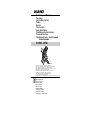 1
1
-
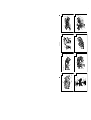 2
2
-
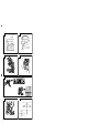 3
3
-
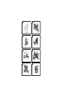 4
4
-
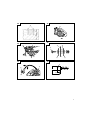 5
5
-
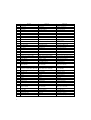 6
6
-
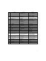 7
7
-
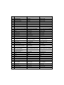 8
8
-
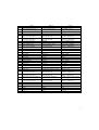 9
9
-
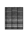 10
10
-
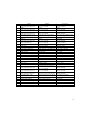 11
11
-
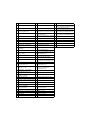 12
12
-
 13
13
-
 14
14
-
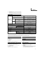 15
15
-
 16
16
-
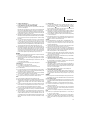 17
17
-
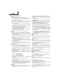 18
18
-
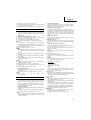 19
19
-
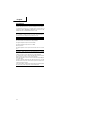 20
20
-
 21
21
-
 22
22
-
 23
23
-
 24
24
-
 25
25
-
 26
26
-
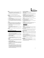 27
27
-
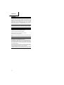 28
28
-
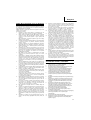 29
29
-
 30
30
-
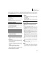 31
31
-
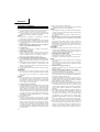 32
32
-
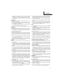 33
33
-
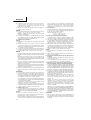 34
34
-
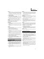 35
35
-
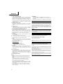 36
36
-
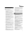 37
37
-
 38
38
-
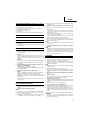 39
39
-
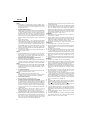 40
40
-
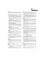 41
41
-
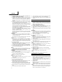 42
42
-
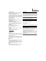 43
43
-
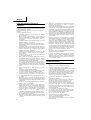 44
44
-
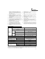 45
45
-
 46
46
-
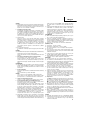 47
47
-
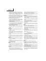 48
48
-
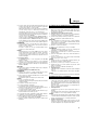 49
49
-
 50
50
-
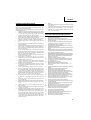 51
51
-
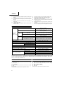 52
52
-
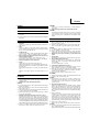 53
53
-
 54
54
-
 55
55
-
 56
56
-
 57
57
-
 58
58
-
 59
59
-
 60
60
-
 61
61
-
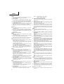 62
62
-
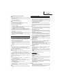 63
63
-
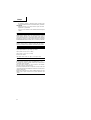 64
64
-
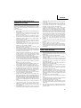 65
65
-
 66
66
-
 67
67
-
 68
68
-
 69
69
-
 70
70
-
 71
71
-
 72
72
-
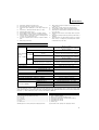 73
73
-
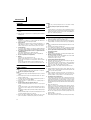 74
74
-
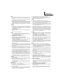 75
75
-
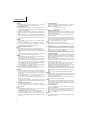 76
76
-
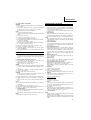 77
77
-
 78
78
-
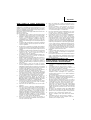 79
79
-
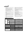 80
80
-
 81
81
-
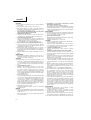 82
82
-
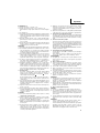 83
83
-
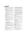 84
84
-
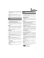 85
85
-
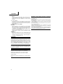 86
86
-
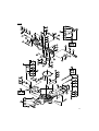 87
87
-
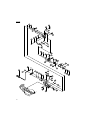 88
88
-
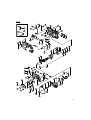 89
89
-
 90
90
-
 91
91
-
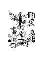 92
92
-
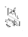 93
93
-
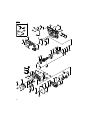 94
94
-
 95
95
-
 96
96
-
 97
97
-
 98
98
-
 99
99
-
 100
100
-
 101
101
-
 102
102


Hikoki C8FSHE Slide Compound Miter Saw Kullanma talimatları
- Kategori
- Elektrikli aletler
- Tip
- Kullanma talimatları