
About interface module
MIM-B14A is an interface module that has 2 outputs and 1 input. It is mainly applied to refrigerant leak detector system.
English
External Contact Interface Module (MIM-B14A)
Components
Product
Name
Circuit board Circuit board case Wiring harness Screw
Installation
manual
Q'TY 1EA 1EA 1EA for Each Wire 2EA 1EA
Shape
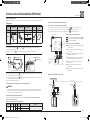
Installation
1. Mount the circuit board case ( ) with screws ( ) inside the outdoor unit control box or at another
appropriate location (Figure 1).
2. Align the circuit board( ) with the case and lock it into place using the locking tab.
Figure 1. Mounting the circuit board case Figure 2. Wiring the module
Screw
Circuit board case
Additional holes to use if necessory
Holes for
installing
screws
Connect wire
Connect wire
3. Connect the 2-pin wiring harness( ) to the interface module at CN83 (Figure 2) and to the outdoor
unit at "GAS LEAK" connector (Main PCB).
4. Connect the 4-pin wiring harness(
) to the interface module at CN81 (Figure 2) and to the outdoor
unit at "PUMP DOWN" connector (Main PCB).
5. Restore power to the outdoor unit.
Shut off power to the outdoor unit before wiring the module.
WARNING
• Disconnect all electric power, including remote disconnects before servicing. Follow proper lockout/tagout
procedures to ensure the power cannot be inadvertently energized. Failure to disconnect power before
servicing could result in death or serious injury.
Installation option setting of outdoor unit
Turn on the outdoor unit and configure outdoor unit options. Refer to Table 1 and the option section of the
outdoor unit installation manual.
Table 1. Option setting of outdoor unit for MIM-B14A
Input unit SEG1 SEG2 SEG3 SEG4 Function of the option Remarks
Main 1 9
0 0 Disabled (Factory default)
If the gas leak occurred it should be
entered in the pumpdown operation.
0 1 Enabled
DB68-07112A-00
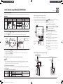
Example of refrigerant leak detector operation
Figure 3. External contact interface module wiring diagram
1. The refrigerant leak detection signal is sent to the outdoor unit
- through the DDC RL#2 port.
2. The lock signal of the high pressure valve is output from the - port of the outdoor unit.
3. The lock signal of the low pressure valve is output from the
- port of the outdoor unit.
(Dry Contact output)
Digital Output (RL#3)
Digital Input (DI#2)
Digital Output
(RL#0)
Digital Output
(RL#1)
Digital Output
(Dry Contact)
(RL#2)
DI#1
DO#2
DO#1
(Dry Contact/
Relay output)
(Dry Contact/
Relay output)
(Dry
Contact
input)
DDC
※ Terms and description
DDC : Direct Digital Control
DO : Digital Output
DI : Digital Input
RL : RELAY
[ B14A Relay's contact function/specification ]
- :Dry Contact Output, NORMAL OPEN TYPE (DO#1)
- :
Dry Contact Output, NORMAL OPEN TYPE (DO#2)
- : Dry Contact Input (DI#1)
[ DDC Relay's contact function/specification ]
RL#0: Digital Output, outputs controls that lock the high
pressure valve.
RL#1: Digital Output, outputs controls that lock the low
pressure valve.
RL#2: Digital Output, outputs signals that can detect the
refrigerant leak (to outdoor)
RL#3: Digital Output, outputs signals that can detect the
refrigerant leak (to external control system)
DI#0: Digital Input, inputs signals that lock the high
pressure valve.
DI#1: Digital Input, inputs signals that lock the low
pressure valve.
DI#2: Digital Input, resets the DDC status (reset outputs
of RL#0 to #3)
Example of the RLD System connection
EXTERNAL CONTROL SYSTEM
MODBUS/TCP
TCP/IP (Daisy Chain)
(Field supplied)
(Low pressure valve)
(High pressure valve)
(Field supplied)
(RL#3)
(RL#2)
(DI#0)
DI
Detector
Relay
(Field supplied)
Sensor
RL
(RL#0)
(RL#1)
(DI#1)
Master DDC Slave DDC
Interface
Module
(MIM-B14A)
Digital Input
(DI#1) (DI#0)
SOL MIM-B14 IM-EN_DB68-07112A-00.indd 22-23 2017-02-08 오후 3:25:31

Arayüz modülü hakkında
MIM-B14A, 2 çıkış ve 1 girişe sahip bir arayüz modülüdür. Genellikle soğutucu kaçağı algılama sistemlerinde uygulanır.
Türkçe
Harici Kontak Arayüz Modülü (MIM-B14A)
Bileşenler
Ürün Adı Devre kartı Devre kartı kasası Kablo demeti Vida Kurulum kılavuzu
Adet 1 ADET 1 ADET Her Kablo için 1 ADET 2 ADET 1 ADET
Şekil
Kurulum
1. Devre kartı kasasını ( ), vidaları ( ) kullanarak dış ünite kontrol kutusunun içine veya uygun başka bir
konuma monte edin (Şekil 1).
2. Devre kartını ( ) kasa ile hizalayın ve kilitleme tırnağını kullanarak yerine sabitleyin.
Şekil 1. Devre kartı kasasını monte etme Şekil 2. Modülün kablolarını takma
Vida
Devre kartı kasası
Gerekirse kullanılabilecek ek delikler
Vidaların takılacağı
delikler
Kabloyu bağlayın
Kabloyu bağlayın
3. 2 pinli kablo demetini ( ) arayüz modülüne CN83'te (Şekil 2) ve dış üniteye "GAS LEAK"
konektöründe (Ana PCB) bağlayın.
4. 4 pinli kablo demetini (
) arayüz modülüne CN81'de (Şekil 2) ve dış üniteye "PUMP DOWN"
konektöründe (Ana PCB) bağlayın.
5. Dış ünitenin gücünü tekrar açın.
Modülün kablolarını takmadan önce dış üniteye giden gücü kapatın.
UYARI
• Bakım yapmadan önce, uzaktan bağlantı kesme dahil tüm elektrik bağlantılarını kesin. Gücün hatayla
açılmasını engelleyecek uygun kilitleme/etiketleme prosedürlerini uygulayın. Bakım öncesinde gücün
kapatılmaması, ölüme veya ciddi yaralanmalara yol açabilir.
Dış ünitenin kurulum seçeneği ayarı
Dış üniteyi açın ve dış ünite seçeneklerini yapılandırın. Tablo 1'e ve dış ünite kurulum kılavuzunun seçenekler
bölümüne başvurun.
Tablo 1. MIM-B14A için dış ünitenin seçenek ayarı
Giriş ünitesi SEG1 SEG2 SEG3 SEG4 Seçeneğin işlevi Açıklamalar
Ana 1 9
0 0 Devre dışı (Fabrika varsayılanı) Soğutucu kaçağı olursa, gazı dış
üniteye toplama operasyonu
başlamalıdır.
0 1 Etkin
DB68-07112A-00
Soğutucu kaçağı algılama operasyonu örneği
Şekil 3. Harici kontak arayüz modülü kablo diyagramı
1. Soğutucu kaçağı algılama sinyali, DDC RL#2 bağlantı noktası
- aracılığıyla dış üniteye gönderiliyor.
2. Yüksek basınç valfını kilitleme sinyali, dış ünitenin - bağlantı noktasından çıkıştır.
3. Düşük basınç valfını kilitleme sinyali, dış ünitenin
- bağlantı noktasından çıkıştır.
DI#1 DO#2 DO#1
(Kuru Kontak çıkışı)
Dijital Çıkış (RL#3)
Dijital Giriş (DI#2)
Dijital Çıkış
(RL#0)
Dijital Çıkış
(RL#1)
Dijital Çıkış
(Kuru Kontak)
(RL#2)
Dijital Giriş
(DI#1) (DI#0)
(Kuru Kontak/
Röle çıkışı)
(Kuru Kontak/
Röle çıkışı)
(Kuru
Kontak
girişi)
DDC
※ Terimler ve açıklamaları
DDC : Doğrudan Dijital Kontrol
DO : Dijital Çıkış
DI : Dijital Giriş
RL : RÖLE
[ B14A Rölesinin kontak işlevi/özellikleri ]
- : Kuru Kontak Çıkışı, NORMAL AÇIK TÜR (DO#1)
-
:
Kuru Kontak Çıkışı, NORMAL AÇIK TÜR (DO#2)
-
: Kuru Kontak Girişi (DI#1)
[ DDC Rölesinin kontak işlevi/özellikleri ]
RL#0: Dijital Çıkış, yüksek basınç valfını kilitleyen
kontrol çıkışı yapar.
RL#1: Dijital Çıkış, düşük basınç valfını kilitleyen
kontrol çıkışı yapar.
RL#2: Dijital Çıkış, soğutucu kaçağını algılayabilen
sinyal çıkışı yapar (dış üniteye)
RL#3: Dijital Çıkış, soğutucu kaçağını algılayabilen
sinyal çıkışı yapar (hari ̇ci ̇ kontrol si ̇stemi ̇)
DI#0: Dijital Giriş, yüksek basınç valfını kilitleyen sinyal
girişi yapar.
DI#1: Dijital Giriş, düşük basınç valfını kilitleyen sinyal
girişi yapar.
DI#2: Dijital Giriş, DDC durumunu sıfırlar (RL#0-#3
çıkışlarını sıfırlar)
Soğutucu kaçağı Algılama Sistemi bağlantı örneği
HARİCİ KONTROL SİSTEMİ
MODBUS/TCP
TCP/IP (Papatya Zinciri)
(Saha temini)
(Düşük basınç valfi)
(Yüksek basınç valfi)
(Saha temini)
(RL#3)
(RL#2)
(DI#0)
DI
Dedektör
Röle
(Saha temini)
Sensör
RL
(RL#0)
(RL#1)
(DI#1)
Yönetici DDC Yardımcı DDC
Arayüz
Modülü
(MIM-B14A)
SOL MIM-B14 IM-EN_DB68-07112A-00.indd 24-25 2017-02-08 오후 3:25:32
-
 1
1
-
 2
2


