
Version 1.0
Published July 2015
Copyright©2015 ASRock INC. All rights reserved.
Copyright Notice:
No part of this documentation may be reproduced, transcribed, transmitted, or
translated in any language, in any form or by any means, except duplication of
documentation by the purchaser for backup purpose, without written consent of
ASRock Inc.
Products and corporate names appearing in this documentation may or may not
be registered trademarks or copyrights of their respective companies, and are used
only for identication or explanation and to the owners’ benet, without intent to
infringe.
Disclaimer:
Specications and information contained in this documentation are furnished for
informational use only and subject to change without notice, and should not be
constructed as a commitment by ASRock. ASRock assumes no responsibility for
any errors or omissions that may appear in this documentation.
With respect to the contents of this documentation, ASRock does not provide
warranty of any kind, either expressed or implied, including but not limited to
the implied warranties or conditions of merchantability or tness for a particular
purpose.
In no event shall ASRock, its directors, ocers, employees, or agents be liable for
any indirect, special, incidental, or consequential damages (including damages for
loss of prots, loss of business, loss of data, interruption of business and the like),
even if ASRock has been advised of the possibility of such damages arising from any
defect or error in the documentation or product.
is device complies with Part 15 of the FCC Rules. Operation is subject to the following
two conditions:
(1) this device may not cause harmful interference, and
(2) this device must accept any interference received, including interference that
may cause undesired operation.
CALIFORNIA, USA ONLY
e Lithium battery adopted on this motherboard contains Perchlorate, a toxic substance
controlled in Perchlorate Best Management Practices (BMP) regulations passed by the
California Legislature. When you discard the Lithium battery in California, USA, please
follow the related regulations in advance.
“Perchlorate Material-special handling may apply, see www.dtsc.ca.gov/hazardouswaste/
perchlorate”
ASRock Website: http://www.asrock.com

1
English
H110M-DVS/D3
Intel
H110
DDR3_B1 (64 bit, 240-pin module)
DDR3_A1 (64 bit, 240-pin module)
CMOS
Battery
Super
I/O
ATXPWR1
Top:
RJ-45
USB 2.0
T: USB0
B: USB1
CLRCMOS1
1
HDLED RESET
PLED PWRBTN
PANEL1
1
USB4_5
COM1
1
1
HD_AUDIO1
H110M-DVS/D3
CHA_FAN1
RoHS
7
9
12
16
15
2
CPU_FAN1
3
4
6
5
1
128Mb
BIOS
Audio
CODEC
PCIE1
PCI Express 3.0
TPMS1
1
1
USB3_4_5
PCIE3
USB 2.0
T: USB2
B: USB3
Top:
LINE I N
Cent er:
FRON T
Bott om:
MIC IN
1
ATX 12V1
USB 3.0
T: USB0
B: USB1
PS2
Keyboard
/Mouse
SPK_CI1
1
PCIE2
Front USB 3.0
8
10
11
13
14
17
VGA1
DVI1
SATA3 _0 S ATA3_2
SATA3 _1 S ATA3_3
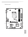
Motherboard Layout

2
English
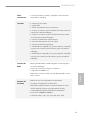
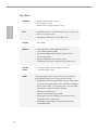
No. Description
1 ATX 12V Power Connector (ATX12V1)
2 CPU Fan Connector (CPU_FAN1)
3 2 x 240-pin DDR3/DDR3L DIMM Slots (DDR3_A1, DDR3_B1)
4 ATX Power Connector (ATXPWR1)
5 USB 3.0 Header (USB3_4_5)
6 SATA3 Connector (SATA3_2)
7 SATA3 Connector (SATA3_3)
8 SATA3 Connector (SATA3_1)
9 SATA3 Connector (SATA3_0)
10 Clear CMOS Jumper (CLRMOS1)
11 System Panel Header (PANEL1)
12 USB 2.0 Header (USB4_5)
13 Chassis Intrusion and Speaker Header (SPK_CI1)
14 TPM Header (TPMS1)
15 COM Port Header (COM1)
16 Chassis Fan Connector (CHA_FAN1)
17 Front Panel Audio Header (HD_AUDIO1)

3
English
H110M-DVS/D3
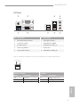
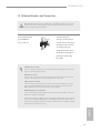
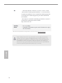
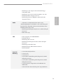
I/O Panel
No. Description No. Description
1 PS/2 Mouse/Keyboard Port 6 Microphone (Pink)**
2 D-Sub Port (VGA1) 7 USB 2.0 Ports (USB01)
3 LAN RJ-45 Port* 8 USB 2.0 Ports (USB_23)
4 Line In (Light Blue)** 9 DVI-D Port
5 Front Speaker (Lime)** 10 USB 3.0 Ports (USB3_01)
6
7
8
9
3
5
4
10
1
2
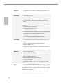
* ere are two LEDs on each LAN port. Please refer to the table below for the LAN port LED indications.
Activity / Link LED Speed LED
Status Description Status Description
O No Link O 10Mbps connection
Blinking Data Activity Orange 100Mbps connection
On Link Green 1Gbps connection
ACT/LINK LED
SPEED LED
LAN Port

4
English
** To congure 7.1 CH HD Audio, it is required to use an HD front panel audio module and enable the multi-
channel audio feature through the audio driver.
Please set Speaker Conguration to “7.1 Speaker”in the Realtek HD Audio Manager.
Function of the Audio Ports in 7.1-channel Conguration:
Port Function
Light Blue (Rear panel) Rear Speaker Out
Lime (Rear panel) Front Speaker Out
Pink (Rear panel) Central /Subwoofer Speaker Out
Lime (Front panel) Side Speaker Out

5
English
H110M-DVS/D3
1 Introduction
ank you for purchasing ASRock H110M-DVS/D3 motherboard, a reliable
motherboard produced under ASRock’s consistently stringent quality control.
It delivers excellent performance with robust design conforming to ASRock’s
commitment to quality and endurance.
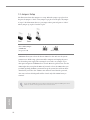
1.1 Package Contents
• ASRock H110M-DVS/D3 Motherboard (Micro ATX Form Factor)
• ASRock H110M-DVS/D3 Quick Installation Guide
• ASRock H110M-DVS/D3 Support CD
• 2 x Serial ATA (SATA) Data Cables (Optional)
• 1 x I/O Panel Shield
Because the motherboard specications and the BIOS soware might be updated, the
content of this documentation will be subject to change without notice. In case any modi-
cations of this documentation occur, the updated version will be available on ASRock’s
website without further notice. If you require technical support related to this mother-
board, please visit our website for specic information about the model you are using. You
may nd the latest VGA cards and CPU support list on ASRock’s website as well. ASRock
website http://www.asrock.com.

6
English
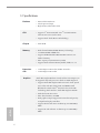
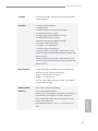
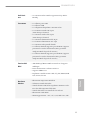
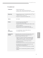
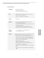
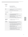
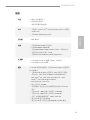
1.2 Specications
Platform
• Micro ATX Form Factor
• Solid Capacitor design
• High Density Glass Fabric PCB
CPU
• Supports 6
th
Generation Intel® Core
TM
i7/i5/i3/Pentium®/
Celeron® Processors (Socket 1151)
• Supports Intel® Turbo Boost 2.0 Technology
Chipset
• Intel® H110
Memory
• Dual Channel DDR3/DDR3L Memory Technology
• 2 x DDR3/DDR3L DIMM Slots
• Supports DDR3/DDR3L 1600/1333/1066 non-ECC, un-
buered memory
• Max. capacity of system memory: 32GB
• Supports Intel® Extreme Memory Prole (XMP) 1.3 / 1.2
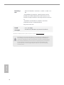
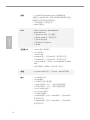
Expansion
Slot
• 1 x PCI Express 3.0 x16 Slot (PCIE1: x16 mode)
• 2 x PCI Express 2.0 x1 Slots
Graphics
* Intel® HD Graphics Built-in Visuals and the VGA outputs can
be supported only with processors which are GPU integrated.
• Supports Intel® HD Graphics Built-in Visuals : Intel® Quick
Sync Video with AVC, MVC (S3D) and MPEG-2 Full
HW Encode1, Intel® InTru
TM
3D, Intel® Clear Video HD
Technology, Intel® Insider
TM
, Intel® HD Graphics 510/530
• Pixel Shader 5.0, DirectX 12
• Max. shared memory 1792MB
• Dual graphics output: Support DVI-D and D-Sub ports by
independent display controllers
• Supports DVI-D with max. resolution up to 1920x1200 @
60Hz
• Supports D-Sub with max. resolution up to 1920x1200 @
60Hz

7
English
H110M-DVS/D3
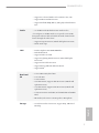
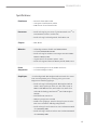
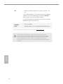
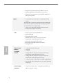
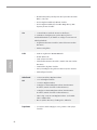
• Supports Accelerated Media Codecs: HEVC, VP8, VP9
• Supports HDCP with DVI-D Port
• Supports Full HD 1080p Blu-ray (BD) playback with DVI-D
Port
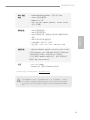
Audio
• 7.1 CH HD Audio (Realtek ALC887 Audio Codec)
* To congure 7.1 CH HD Audio, it is required to use an HD
front panel audio module and enable the multi-channel audio
feature through the audio driver.
• Supports Surge Protection (ASRock Full Spike Protection)
• ELNA Audio Caps
LAN
• PCIE x1 Gigabit LAN 10/100/1000 Mb/s
• Realtek RTL8111E
• Supports Wake-On-LAN
• Supports Lightning/ESD Protection (ASRock Full Spike
Protection)
• Supports LAN Cable Detection
• Supports Energy Ecient Ethernet 802.3az
• Supports PXE
Rear Panel
I/O
• 1 x PS/2 Mouse/Keyboard Port
• 1 x D-Sub Port
• 1 x DVI-D Port
• 4 x USB 2.0 Ports (Supports ESD Protection (ASRock Full
Spike Protection))
• 2 x USB 3.0 Ports (Supports ESD Protection (ASRock Full
Spike Protection))
• 1 x RJ-45 LAN Port with LED (ACT/LINK LED and SPEED
LED)
• HD Audio Jacks: Line in / Front Speaker / Microphone
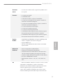
Storage
• 4 x SATA3 6.0 Gb/s Connectors, support NCQ, AHCI and
Hot Plug

8
English
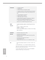
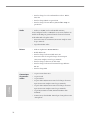
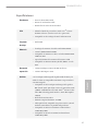
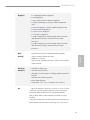
Connector
• 1 x COM Port Header
• 1 x TPM Header
• 1 x Chassis Intrusion and Speaker Header
• 1 x CPU Fan Connector (4-pin) (Smart Fan Speed Control)
• 1 x Chassis Fan Connector (4-pin) (Smart Fan Speed Con-
trol)
• 1 x 24 pin ATX Power Connector
• 1 x 4 pin 12V Power Connector
• 1 x Front Panel Audio Connector
• 1 x USB 2.0 Header (Supports 2 USB 2.0 ports) (Supports
ESD Protection (ASRock Full Spike Protection))
• 1 x USB 3.0 Header (Supports 2 USB 3.0 ports) (Supports
ESD Protection (ASRock Full Spike Protection))
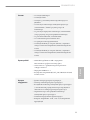
BIOS
Feature
• 128Mb AMI UEFI Legal BIOS with multilingual GUI sup-
port
• ACPI 1.1 Compliant wake up events
• SMBIOS 2.3.1 Support
• CPU, GT_CPU, DRAM, PCH 1.0V, VCCIO, VCCSA Voltage
Multi-adjustment
Hardware
Monitor
• CPU/Chassis temperature sensing
• CPU/Chassis Fan Tachometer
• CPU/Chassis Quiet Fan (Auto adjust chassis fan speed by
CPU temperature)
• CPU/Chassis Fan multi-speed control
• CASE OPEN detection
• Voltage monitoring: +12V, +5V, +3.3V, CPU Vcore, CPU
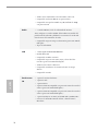
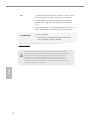
OS
• Microso® Windows® 10 64-bit / 8.1 64-bit / 7 32-bit / 7 64-
bit
* To install Windows® 7 OS, a modied installation disk with
xHCI drivers packed into the ISO le is required. Please refer to
page 62 for more detailed instructions.
* For the updated Windows® 10 driver, please visit ASRock’s
website for details: http://www.asrock.com

9
English
H110M-DVS/D3
Please realize that there is a certain risk involved with overclocking, including adjusting
the setting in the BIOS, applying Untied Overclocking Technology, or using third-party
overclocking tools. Overclocking may aect your system’s stability, or even cause damage to
the components and devices of your system. It should be done at your own risk and expense.
We are not responsible for possible damage caused by overclocking.
* For detailed product information, please visit our website:
http://www.asrock.com
Certica-
tions
• FCC, CE, WHQL
• ErP/EuP ready (ErP/EuP ready power supply is required)

10
English
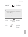
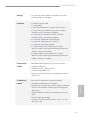
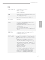
1.3 Jumpers Setup
e illustration shows how jumpers are setup. When the jumper cap is placed on
the pins, the jumper is “Short”. If no jumper cap is placed on the pins, the jumper
is “Open”. e illustration shows a 3-pin jumper whose pin1 and pin2 are “Short”
when a jumper cap is placed on these 2 pins.
Clear CMOS Jumper
(CLRMOS1)
(see p.1, No. 10)
CLRMOS1 allows you to clear the data in CMOS. To clear and reset the system
parameters to default setup, please turn o the computer and unplug the power
cord from the power supply. Aer waiting for 15 seconds, use a jumper cap to
short pin2 and pin3 on CLRMOS1 for 5 seconds. However, please do not clear the
CMOS right aer you update the BIOS. If you need to clear the CMOS when you
just nish updating the BIOS, you must boot up the system rst, and then shut it
down before you do the clear-CMOS action. Please be noted that the password,
date, time, and user default prole will be cleared only if the CMOS battery is
removed.
Clear CMOS
Default
If you clear the CMOS, the case open may be detected. Please adjust the BIOS option “Clear
Status” to clear the record of previous chassis intrusion status.

11
English
H110M-DVS/D3
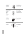
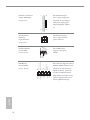
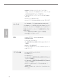
1.4 Onboard Headers and Connectors
System Panel Header
(9-pin PANEL1)
(see p.1, No. 11)
Connect the power
switch, reset switch and
system status indicator on
the chassis to this header
according to the pin
assignments below. Note
the positive and negative
pins before connecting
the cables.
GND
RESET#
PWRBTN#
PLED-
PLED+
GND
HDLED-
HDLED+
1
GND
PWRBTN (Power Switch):
Connect to the power switch on the chassis front panel. You may congure the way to turn
o your system using the power switch.
RESET (Reset Switch):
Connect to the reset switch on the chassis front panel. Press the reset switch to restart the
computer if the computer freezes and fails to perform a normal restart.
PLED (System Power LED):
Connect to the power status indicator on the chassis front panel. e LED is on when the
system is operating. e LED keeps blinking when the system is in S1/S3 sleep state. e
LED is o when the system is in S4 sleep state or powered o (S5).
HDLED (Hard Drive Activity LED):
Connect to the hard drive activity LED on the chassis front panel. e LED is on when the
hard drive is reading or writing data.
e front panel design may dier by chassis. A front panel module mainly consists of power
switch, reset switch, power LED, hard drive activity LED, speaker and etc. When connect-
ing your chassis front panel module to this header, make sure the wire assignments and the
pin assignments are matched correctly.
Onboard headers and connectors are NOT jumpers. Do NOT place jumper caps over these
headers and connectors. Placing jumper caps over the headers and connectors will cause
permanent damage to the motherboard.

12
English
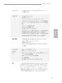
Chassis Intrusion and
Speaker Header
(7-pin SPK_CI1)
(see p.1, No. 13)
Please connect the
chassis intrusion and the
chassis speaker to this
header.
Serial ATA3 Connectors
(SATA3_0)
(see p.1, No. 9)
(SATA3_1)
(see p.1, No. 8)
(SATA3_2)
(see p.1, No. 6)
(SATA3_3)
(see p.1, No. 7)
ese four SATA3
connectors support SATA
data cables for internal
storage devices with up to
6.0 Gb/s data transfer rate.
USB 2.0 Header
(9-pin USB4_5)
(see p.1, No. 12)
DUMMY
GND
GND
+B
-B
USB_PWR
+A
-A
USB_PWR
1
ere is one header on
this motherboard. Each
USB 2.0 header can
support two ports.
USB 3.0 Header
(19-pin USB3_4_5)
(see p.1, No. 5)
1
IntA_PB_D+
Dummy
IntA_PB_D-
GND
IntA_PB_SSTX+
GND
IntA_PB_SSTX-
IntA_PB_SSRX+
IntA_PB_SSRX-
VbusVbus
Vbus
IntA_PA_SSRX-
IntA_PA_SSRX+
GND
IntA_PA_SSTX-
IntA_PA_SSTX+
GND
IntA_PA_D-
IntA_PA_D+
Besides two USB 3.0 ports
on the I/O panel, there
is one header on this
motherboard. Each USB
3.0 header can support
two ports.
1
+5V
DUMMY
SIGNAL
GND
DUMMY
SPEAKER
DUMMY
SATA3_2
SATA3_3
SATA3_0
SATA3_1

13
English
H110M-DVS/D3
Front Panel Audio Header
(9-pin HD_AUDIO1)
(see p.1, No. 17)
J_SENSE
OUT2_L
1
MIC_RET
PRESENCE#
GN D
OUT2_R
MIC2_R
MIC2_L
OUT_RET
is header is for
connecting audio devices
to the front audio panel.
Chassis Fan Connector
(4-pin CHA_FAN1)
(see p.1, No. 16)
GND
FAN_VOLTAGE
CHA_FAN_SPEED
FAN_SPEED_CONTROL
Please connect fan cables
to the fan connector and
match the black wire to
the ground pin.
CPU Fan Connector
(4-pin CPU_FAN1)
(see p.1, No. 2)
GND
FAN_VOLTAGE
CPU_FAN_SPEED
FAN_SPEED_CONTROL
1 2 3 4
is motherboard pro-
vides a 4-Pin CPU fan
(Quiet Fan) connector.
If you plan to connect a
3-Pin CPU fan, please
connect it to Pin 1-3.
1. High Denition Audio supports Jack Sensing, but the panel wire on the chassis must sup-
port HDA to function correctly. Please follow the instructions in our manual and chassis
manual to install your system.
2. If you use an AC’97 audio panel, please install it to the front panel audio header by the
steps below:
A. Connect Mic_IN (MIC) to MIC2_L.
B. Connect Audio_R (RIN) to OUT2_R and Audio_L (LIN) to OUT2_L.
C. Connect Ground (GND) to Ground (GND).
D. MIC_RET and OUT_RET are for the HD audio panel only. You don’t need to connect
them for the AC’97 audio panel.
E. To activate the front mic, go to the “FrontMic” Tab in the Realtek Control panel and
adjust “Recording Volume”.

14
English
ATX Power Connector
(24-pin ATXPWR1)
(see p.1, No. 4)
is motherboard pro-
vides a 24-pin ATX power
connector. To use a 20-pin
ATX power supply, please
plug it along Pin 1 and Pin
13.
ATX 12V Power
Connector
(4-pin ATX12V1)
(see p.1, No. 1)
is motherboard pro-
vides a 4-pin ATX 12V
power connector.
Serial Port Header
(9-pin COM1)
(see p.1, No. 15)
is COM1 header
supports a serial port
module.
TPM Header
(17-pin TPMS1)
(see p.1, No. 14)
is connector supports Trusted
Platform Module (TPM) system,
which can securely store keys,
digital certicates, passwords,
and data. A TPM system also
helps enhance network security,
protects digital identities, and
ensures platform integrity.
1
12
13
24
1
GND
SMB_DATA_MAIN
LAD2
LAD1
GND
S_PWRDWN#
SERIRQ#
GND
PCICLK
PCIRST#
LAD3
+3V
LAD0
+3VSB
GND
FRAME
SMB_CLK_MAIN
CCTS#1
RRTS#1
DDSR#1
DDTR#1
RRXD1
GND
TTXD1
DDCD#1
1
RRI#1

15
H110M-DVS/D3
Deutsch
Technische Daten
Plattform
• Micro-ATX-Formfaktor
• Feststoondensator-Design
• Leiterplatte mit hochdichtem Glasgewebe
Prozessor
• Unterstützt die Prozessoren Intel® Core
TM
i7/i5/i3/Pentium®/
Celeron® der 6. Generation (Sockel 1151)
• Unterstützt Intel® Turbo Boost 2.0-Technologie
Chipsatz
• Intel® H110
Speicher
• Dualkanal-DDR3/DDR3L-Speichertechnologie
• 2 x DDR3/DDR3L-DIMM-Steckplätze
• Unterstützt DDR3/DDR3L 1600/1333/1066 non-ECC,
ungepuerter Speicher
• Systemspeicher, max. Kapazität: 32GB
• Unterstützt Intel® Extreme Memory Prole (XMP)1.3/1.2
Erweiter-
ungssteckplatz
• 1 x PCI-Express 3.0-x16-Steckplatz (PCIE1:x16-Modus)
• 2 x PCI-Express 2.0-x1-Steckplätze
Grakkarte
* Integrierte Intel® HD Graphics-Visualisierung und VGA-
Ausgänge können nur mit Prozessoren unterstützt werden, die
GPU-integriert sind.
• Unterstützt integrierte Intel® HD Graphics-Visualisierung:
Intel® Quick Sync Video mit AVC, MVC (S3D) und MPEG-2
Full HW Encode1, Intel® InTru
TM
3D, Intel® Clear Video HD
Technology, Intel® Insider
TM
, Intel® HD Graphics 510/530
• Pixel Shader 5.0, DirectX 12
• Max. geteilter Speicher: 1792 MB
• Dualer Grakkartenausgang Unterstützt DVI-D- und
D-Sub-Ports durch unabhängige Monitor-Controller
• Unterstützt DVI-D mit maximaler Auösung von 1920 x
1200 bei 60 Hz
• Unterstützt D-Sub mit maximaler Auösung von 1920 x
1200 bei 60 Hz

16
Deutsch
• Unterstützt beschleunigte Mediencodecs: HEVC, VP8, VP9
• Unterstützt HDCP mit DVI-D-Port
• Unterstützt Blu-ray- (BD) Wiedergabe (Full HD/1080p) mit
DVI-D-Port
Audio
• 7.1-Kanal-HD-Audio (Realtek ALC887-Audiocodec)
*Zur Konguration von 7.1-Kanal-HD-Audio müssen Sie ein
HD-Frontblenden-Audiomodul nutzen und den Mehrkanalton
über den Audiotreiber aktivieren.
• Unterstützt Überspannungsschutz (ASRock Full Spike Pro-
tection)
• ELNA-Audiokondensatoren
LAN
• PCIE x1 Gigabit LAN 10/100/1000 Mb/s
• Realtek RTL8111E
• Unterstützt Wake-On-LAN
• Unterstützt Blitzschutz/Schutz gegen elektrostatische Entla-
dung (ASRock Full Spike Protection)
• Unterstützt LAN-Kabelerkennung
• Unterstützt energieezientes Ethernet 802.3az
• Unterstützt PXE
Rückblende,
E/A
• 1 x PS/2-Maus-/Tastaturanschluss
• 1 x D-Sub-Port
• 1 x DVI-D-Port
• 4 x USB 2.0-Ports (unterstützt Schutz gegen elektrostatische
Entladung (ASRock Full Spike Protection))
• 2 x USB 3.0-Ports (unterstützt Schutz gegen elektrostatische
Entladung (ASRock Full Spike Protection))
• 1 x RJ-45-LAN-Port mit LED (Aktivität/Verbindung-LED
und Geschwindigkeit-LED)
• HD-Audioanschlüsse: Line-in / Vorderer Lautsprecher /
Mikrofon

17
H110M-DVS/D3
Deutsch
Speicher
• 4 x SATA-III-6,0-Gb/s-Anschlüsse, unterstützt NCQ, AHCI
und Hot-Plugging
Anschluss
• 1 x COM-Anschluss-Stileiste
• 1 x TPM-Stileiste
• 1 x Gehäuseeingri- und Lautsprecher-Stileiste
• 1 x CPU-Lüeranschluss (4-polig)
(intelligente Lüergeschwindigkeitssteuerung)
• 1 x Gehäuselüeranschluss (4-polig)
(intelligente Lüergeschwindigkeitssteuerung)
• 1 x 24-poliger ATX-Netzanschluss
• 1 x 4-poliger 12-V-Netzanschluss
• 1 x Audioanschluss an Frontblende
• 1 x USB 2.0-Stileiste (unterstützt 2 USB 2.0-Ports) (unter-
stützt Schutz gegen elektrostatische Entladung (ASRock Full
Spike Protection))
• 1 x USB 3.0-Stileiste (unterstützt 2 USB 3.0-Ports) (unter-
stützt Schutz gegen elektrostatische Entladung (ASRock Full
Spike Protection))
BIOS-Funktion
• 128-Mb-AMI-UEFI-Legal-BIOS mit Unterstützung mehr-
sprachiger grascher Benutzerschnittstellen
• ACPI 1.1-konforme Aufweckereignisse
• SMBIOS 2.3.1-Unterstützung
• CPU, GT_CPU, DRAM, PCH 1,0V, VCCIO, VCCSA Mehr-
fachspannungsanpassung
Hardwareüber-
wachung
• CPU-/Gehäusetemperaturerkennung
• CPU-/Gehäuselüertachometer
• Lautloser CPU-/Gehäuselüer (automatische Anpassung der
Gehäuselüergeschwindigkeit durch CPU-Temperatur)
• CPU-/Gehäuselüer-Mehrfachgeschwindigkeitssteuerung
• Gehäuse-oen-Erkennung
• Spannungsüberwachung: +12 V, +5 V, +3,3 V, CPU Vcore,
CPU

18
Deutsch
Betriebssys-
tem
• Microso® Windows® 10, 64 Bit / 8.1, 64 Bit / 7, 32 Bit / 7, 64
Bit
* Zur Installation des Windows® 7-Betriebssystems wird ein
modiziertes Installationslaufwerk mit xHCI-Treibern in der
ISO-Datei benötigt. Detaillierte Anweisungen nden Sie auf Seite
62.
* Einzelheiten zum aktualisierten Windows® 10-Treiber
entnehmen Sie bitte der ASRock-Webseite:
http://www.asrock.com
Zerti-
zierungen
• FCC, CE, WHQL
• ErP/EuP ready (ErP/EuP ready-Netzteil erforderlich)
Bitte beachten Sie, dass mit einer Übertaktung, zu der die Anpassung von BIOS-Einstellungen,
die Anwendung der Untied Overclocking Technology oder die Nutzung von Übertaktung-
swerkzeugen von Drittanbietern zählen, bestimmte Risiken verbunden sind. Eine Übertaktung
kann sich auf die Stabilität Ihres Systems auswirken und sogar Komponenten und Geräte Ihres
Systems beschädigen. Sie sollte auf eigene Gefahr und eigene Kosten durchgeführt werden.
Wir übernehmen keine Verantwortung für mögliche Schäden, die durch eine Übertaktung
verursacht wurden.
* Detaillierte Produktinformationen nden Sie auf unserer Webseite: http://www.asrock.com

19
H110M-DVS/D3
Français
Spécications
Plateforme
• Facteur de forme Micro ATX
• Conception à condensateurs solides
• PCB en tissu de verre haute densité
Processeur
• Prend en charge les processeurs 6
e
génération Intel® Core
TM
i7/
i5/i3/Pentium®/Celeron® (Socket 1151)
• Prend en charge la technologie Intel® Turbo Boost 2.0
Chipset
• Intel® H110
Mémoire
• Technologie mémoire double canal DDR3/DDR3L
• 2 x fentes DIMM DDR3/DDR3L
• Prend en charge les mémoires sans tampon non ECC DDR3/
DDR3L 1600/1333/1066
• Capacité max. de la mémoire système : 32Go
• Prend en charge Intel® Extreme Memory Prole (XMP)1.3/1.2
Fente
d’expansion
• 1 x fente PCI Express 3.0 x 16 (PCIE1:mode x16)
• 2 x fentes PCI Express 2.0 x1
Graphiques
* La technologie Intel® HD Graphics Built-in Visuals et les sorties
VGA sont uniquement prises en charge par les processeurs
intégrant un contrôleur graphique.
• Prend en charge la technologie Intel® HD Graphics Built-in
Visuals : Intel® Quick Sync Video avec AVC, MVC (S3D) et
MPEG-2 Full HW Encode1, Intel® InTru
TM
3D, Intel® Clear
Video HD Technology, Intel® Insider
TM
, Intel® HD Graphics
510/530
• Pixel Shader 5.0, DirectX 12
• Mémoire partagée max. 1792Mo
• Double sortie graphique: Prend en charge les ports D-Sub et
DVI-D via contrôleurs d’achage indépendants
• Prend en charge le mode DVI-D avec une résolution maximale
de 1920x1200 @ 60Hz
• Prend en charge le mode D-Sub avec une résolution maximale
de 1920x1200 @ 60Hz
Sayfa yükleniyor...
Sayfa yükleniyor...
Sayfa yükleniyor...
Sayfa yükleniyor...
Sayfa yükleniyor...
Sayfa yükleniyor...
Sayfa yükleniyor...
Sayfa yükleniyor...
Sayfa yükleniyor...
Sayfa yükleniyor...
Sayfa yükleniyor...
Sayfa yükleniyor...
Sayfa yükleniyor...
Sayfa yükleniyor...
Sayfa yükleniyor...
Sayfa yükleniyor...
Sayfa yükleniyor...
Sayfa yükleniyor...
Sayfa yükleniyor...
Sayfa yükleniyor...
Sayfa yükleniyor...
Sayfa yükleniyor...
Sayfa yükleniyor...
Sayfa yükleniyor...
Sayfa yükleniyor...
Sayfa yükleniyor...
Sayfa yükleniyor...
Sayfa yükleniyor...
Sayfa yükleniyor...
Sayfa yükleniyor...
Sayfa yükleniyor...
Sayfa yükleniyor...
Sayfa yükleniyor...
Sayfa yükleniyor...
Sayfa yükleniyor...
Sayfa yükleniyor...
Sayfa yükleniyor...
Sayfa yükleniyor...
Sayfa yükleniyor...
Sayfa yükleniyor...
Sayfa yükleniyor...
Sayfa yükleniyor...
Sayfa yükleniyor...
Sayfa yükleniyor...
Sayfa yükleniyor...
Sayfa yükleniyor...
-
 1
1
-
 2
2
-
 3
3
-
 4
4
-
 5
5
-
 6
6
-
 7
7
-
 8
8
-
 9
9
-
 10
10
-
 11
11
-
 12
12
-
 13
13
-
 14
14
-
 15
15
-
 16
16
-
 17
17
-
 18
18
-
 19
19
-
 20
20
-
 21
21
-
 22
22
-
 23
23
-
 24
24
-
 25
25
-
 26
26
-
 27
27
-
 28
28
-
 29
29
-
 30
30
-
 31
31
-
 32
32
-
 33
33
-
 34
34
-
 35
35
-
 36
36
-
 37
37
-
 38
38
-
 39
39
-
 40
40
-
 41
41
-
 42
42
-
 43
43
-
 44
44
-
 45
45
-
 46
46
-
 47
47
-
 48
48
-
 49
49
-
 50
50
-
 51
51
-
 52
52
-
 53
53
-
 54
54
-
 55
55
-
 56
56
-
 57
57
-
 58
58
-
 59
59
-
 60
60
-
 61
61
-
 62
62
-
 63
63
-
 64
64
-
 65
65
-
 66
66


diğer dillerde
- español: ASROCK H110M-DVS/D3 Manual de usuario
- français: ASROCK H110M-DVS/D3 Manuel utilisateur
- italiano: ASROCK H110M-DVS/D3 Manuale utente
- 日本語: ASROCK H110M-DVS/D3 ユーザーマニュアル
- português: ASROCK H110M-DVS/D3 Manual do usuário
- English: ASROCK H110M-DVS/D3 User manual
- русский: ASROCK H110M-DVS/D3 Руководство пользователя
İlgili makaleler
-
ASROCK N3050B-ITX Yükleme Rehberi
-
ASROCK N3150-ITX Yükleme Rehberi
-
-
-
-
-
-
-
ASROCK FM2A58 Pro+ Kullanım kılavuzu
-
ASROCK Z87iCafe4 Hızlı başlangıç Kılavuzu