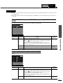
Yamaha LPX-500 Kullanım kılavuzu
- Kategori
- Projektörler
- Tip
- Kullanım kılavuzu

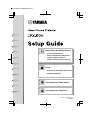
OWNER'S MANUAL
LPX-500
Home Cinema Projector
an (English)
403256900
U C A G B R T

I
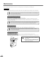
IMPORTANT SAFETY INSTRUCTIONS
•
••
•
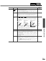
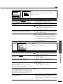
Explanation of Graphical Symbols
1
Read these instructions.
2
Keep these instructions.
3
Heed all warnings.
4
Follow all instructions.
5
Do not use this apparatus near water.
6
Clean only with dry cloth.
7
Do not block any ventilation openings. Install in
accordance with the manufacturer’s instructions.
8
Do not install near any heat sources such as radiators,
heat registers, stoves, or other apparatus (including
amplifiers) that produce heat.
9
Do not defeat the safety purpose of the polarized or
grounding-type plug. A polarized plug has two blades
with one wider than the other. A grounding type plug
has two blades and a third grounding prong. The wide
blade or the third prong are provided for your safety.
If the provided plug does not fit into your outlet,
consult an electrician for replacement of the obsolete
outlet.
10
Protect the power cord from being walked on or
pinched particularly at plugs, convenience
receptacles, and the point where they exit from the
apparatus.
11
Only use attachments/accessories specified by the
manufacturer.
12
Use only with the cart, stand, tripod,
bracket, or table specified by the
manufacturer, or sold with the
apparatus. When a cart is used, use
caution when moving the cart/
apparatus combination to avoid injury
from tip-over.
13
Unplug this apparatus during lightning storms or
when unused for long periods of time.
14
Refer all servicing to qualified service personnel.
Servicing is required when the apparatus has been
damaged in any way, such as power-supply cord or
plug is damaged, liquid has been spilled or objects
have fallen into the apparatus, the apparatus has been
exposed to rain or moisture, does not operate
normally, or has been dropped.
CAUTION: TO REDUCE THE RISK OF
ELECTRIC SHOCK, DO NOT REMOVE
COVER (OR BACK). NO USER-SERVICEABLE
PARTS INSIDE. REFER SERVICING TO
QUALIFIED SERVICE PERSONNEL.
The lightning flash with arrowhead
symbol, within an equilateral triangle, is
intended to alert you to the presence of
uninsulated “dangerous voltage” within
the product’s enclosure that may be of
sufficient magnitude to constitute a risk
of electric shock to persons.
The exclamation point within an
equilateral triangle is intended to alert
you to the presence of important
operating and maintenance (servicing)
instructions in the literature
accompanying the appliance.
WARNING
TO REDUCE THE RISK OF FIRE OR ELECTRIC
SHOCK, DO NOT EXPOSE THIS UNIT TO RAIN
OR MOISTURE.
IMPORTANT!
Please record the serial number of this unit in the space
below.
Model:
Serial No.:
The serial number is located on the bottom of the unit.
Retain this Owner’s Manual in a safe place for future
reference.
CAUTION
RISK OF ELECTRIC
SHOCK DO NOT
OPEN

II
COMPLIANCE INFORMATION STATEMENT
(DECLARATION OF CONFORMITY PROCEDURE)
Responsible Party: Yamaha Electronics Corporation
Address: 6660 Orangethorpe Avenue
Buena Park, CA90620
Telephone: 714-522-9105
Fax: 714-670-0108
Type of Equipment: Projector
Model Name: LPX-500
This device complies with Part 15 of the FCC Rules.
Operation is subject to the following conditions:
1) this device may not cause harmful interference, and
2) this device must accept any interference received including interference that may cause undesired
operation.
See the user manual instructions if interference to radio reception is suspected.
We Want You Listening For A Lifetime
YAMAHA and the Electronic Industries Association’s Consumer Electronics Group want you to get the most
out of your equipment by playing it at a safe level. One that lets the sound come through loud and clear
without annoying blaring or distortion
—
and, most importantly, without affecting your sensitive hearing.
Since hearing damage from loud sounds is often undetectable until it is too late, YAMAHA and the Electronic
Industries Association’s Consumer Electronics Group recommend you to avoid prolonged exposure from
excessive volume levels.
FCC INFORMATION (for US customers)
1. IMPORTANT NOTICE: DO NOT MODIFY THIS
UNIT!
This product, when installed as indicated in the
instructions contained in this manual, meets FCC
requirements. Modifications not expressly
approved by Yamaha may void your authority,
granted by the FCC, to use the product.
2. IMPORTANT:
When connecting this product to
accessories and/or another product use only high
quality shielded cables. Cable/s supplied with this
product MUST be used. Follow all installation
instructions. Failure to follow instructions could
void your FCC authorization to use this product in
the USA.
3. NOTE:
This product has been tested and found to
comply with the requirements listed in FCC
Regulations, Part 15 for Class “B” digital devices.
Compliance with these requirements provides a
reasonable level of assurance that your use of this
product in a residential environment will not result
in harmful interference with other electronic
devices.
This equipment generates/uses radio frequencies and,
if not installed and used according to the instructions
found in the users manual, may cause interference
harmful to the operation of other electronic devices.
Compliance with FCC regulations does not guarantee
that interference will not occur in all installations. If
this product is found to be the source of interference,
which can be determined by turning the unit “OFF”
and “ON”, please try to eliminate the problem by using
one of the following measures:
Relocate either this product or the device that is being
affected by the interference.
Utilize power outlets that are on different branch
(circuit breaker or fuse) circuits or install AC line
filter/s.
In the case of radio or TV interference, relocate/
reorient the antenna. If the antenna lead-in is 300 ohm
ribbon lead, change the lead-in to coaxial type cable.
If these corrective measures do not produce
satisfactory results, please contact the local retailer
authorized to distribute this type of product. If you can
not locate the appropriate retailer, please contact
Yamaha Electronics Corp., U.S.A. 6660 Orangethorpe
Ave, Buena Park, CA 90620.
The above statements apply ONLY to those products
distributed by Yamaha Corporation of America or its
subsidiaries.

III
Caution: Read this before operating this unit.
•
••
•
To assure the finest performance, please read this
manual carefully. Keep it in a safe place for future
reference.
Installation
•
••
•
Install this unit in a well-ventilated, cool, dry, clean
place with at least 10 cm clearance on the top, right and
left, and at the back of this unit — away from direct
sunlight, heat sources, vibration, dust, moisture, and/or
cold.
•
••
•
Locate this unit away from other electrical appliances,
motors, or transformers to avoid humming sounds. To
prevent fire or electrical shock, do not place this unit
where it may get exposed to rain, water, and/or any type
of liquid.
•
••
•
Do not expose this unit to sudden temperature changes
from cold to hot, and do not locate this unit in an
environment with high humidity (i.e. a room with a
humidifier) to prevent condensation inside this unit,
which may cause an electrical shock, fire, damage to this
unit, and/or personal injury.
•
••
•
On the top of this unit, do not place:
—Other components, as they may cause damage and/or
discoloration on the surface of this unit.
—Burning objects (i.e. candles), as they may cause fire,
damage to this unit, and/or personal injury.
—Containers with liquid in them, as they may cause
electrical shock to the user and/or damage to this unit.
•
••
•
Do not cover this unit with a newspaper, tablecloth,
curtain, etc. in order not to restrict heat dissipation. If the
temperature inside this unit rises too much, it may cause
fire, damage to this unit, and/or personal injury.
•
••
•
When installing this unit on the ceiling, make sure the
ceiling has sufficient strength to support this unit and the
ceiling mounts for an extended period of time.
Installation must be performed only by qualified service
personnel.
Operation
•
••
•
Remove the lens cap before starting any operation of this
unit to prevent the heat from staying around the lens.
Operation with the cap on may cause damage to this
unit.
•
••
•
Do not plug in this unit to a wall outlet until all
connections are complete.
•
••
•
Only the voltage specified on this unit must be used.
Using this unit with a higher voltage than specified is
dangerous and may cause fire, damage to this unit, and/
or personal injury. YAMAHA will not be held
responsible for any damage resulting from use of this
unit with a voltage other than that specified.
•
••
•
Do not use force on switches, knobs and/or cords.
•
••
•
Take care of this unit so that no foreign objects and/or
liquid drop inside this unit.
•
••
•
To prevent damage by lightning, disconnect the power
cord from the wall outlet during an electrical storm.
•
••
•
Do not look into the lens while this unit is turned on. It
may cause serious damage to your eyesight.
•
••
•
Before moving this unit, press
STANDBY/ON
to set
this unit in the standby mode, and disconnect the AC
power plug from the wall outlet.
•
••
•
Do not attempt to modify or fix this unit. Contact
qualified YAMAHA service personnel when any service
is needed. The cabinet should never be opened for any
reason.
•
••
•
When not planning to use this unit for a long period of
time (i.e. vacation), disconnect the AC power plug from
the wall outlet.
•
••
•
When disconnecting the power cord from the wall outlet,
grasp the plug; do not pull the cord.
•
••
•
Be sure to read the “TROUBLESHOOTING” section on
common operating errors before concluding that this unit
is faulty.
Others
•
••
•
Clean the lens carefully so as not to create any scratches
by using a blower or lens paper.
•
••
•
Replace the lamp when the LAMP/COVER indicator
flashes in red after the lamp usage has exceeded 1000
hours. Follow the lamp replacement procedure described
in this manual.
For U.K. customers
•
••
•
If the socket outlets in the home are not suitable for the
plug supplied with this appliance, it should be cut off
and an appropriate 3 pin plug fitted. For details, refer to
the instructions described below.
Note
•
••
•
The plug severed from the mains lead must be destroyed, as
a plug with bared flexible cord is hazardous if engaged in a
live socket outlet.
This unit is not disconnected from the AC power source
as long as it is connected to the wall outlet, even if this
unit itself is turned off. This state is called the standby
mode. In this state, this unit is designed to consume a
very small quantity of power.
IMPORTANT
THE WIRES IN THIS MAINS LEAD ARE
COLOURED IN ACCORDANCE WITH THE
FOLLOWING CODE:
GREEN-AND-YELLOW: EARTH
BLUE: NEUTRAL
BROWN: LIVE
As the colours of the wires in the mains lead of this
apparatus may not correspond with the coloured markings
identifying the terminals in your plug, proceed as follows:
The wire which is coloured GREEN-AND-YELLOW must
be connected to the terminal in the plug which is marked by
the letter E or by the safety earth symbol or coloured
GREEN or GREEN-and-YELLOW.
The wire which is coloured BLUE must be connected to the
terminal which is marked with the letter N or coloured
BLACK.
The wire which is coloured BROWN must be connected to
the terminal which is marked with the letter L or coloured
RED.
For Canadian Customers
To prevent electric shock, match wide blade of plug to
wide slot and fully insert.
This Class B digital apparatus complies with Canadian
ICES-003.

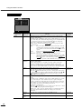
Indications
Notations used in this Owner’s Manual
Indicates procedures where personal injury or damage to the projector may occur if the
procedures are not followed correctly.
Indicates additional information and points which may be useful to know regarding a topic.
Indicates that an explanation of the underlined word or words in front of this symbol appears
in the glossary of terms.
Refer to the “Glossary” in the “Appendix”. (p.61)
Indicates operating methods and the order of operations.
The procedure indicated should be carried out in the order of the numbers.
Procedure

1
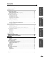
Contents
Notes on Handling and Storage ........................................................................2
Accessories .......................................................................................................3
Features of the Projector ...................................................................................4
Basic Operations
Turning On the Projector ...................................................................................6
Connecting the Power Cord .....................................................................................6
Turning On the Power and Projecting Images .........................................................7
Turning Off the Projector ...................................................................................9
Adjusting the Screen Image ............................................................................11
Adjusting the Image Size .......................................................................................11
Adjusting the Image Angle ....................................................................................11
Correcting Keystone Distortion .............................................................................12
Displaying a Test Pattern .......................................................................................13
Adjusting the Image Quality.............................................................................14
Focusing the Screen Image ....................................................................................14
Selecting the picture mode .....................................................................................14
Selecting the Image Aspect Ratio .......................................................................... 15
Automatic Adjustment of Computer Images .........................................................17
Advanced Operations
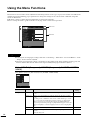
Functions for Enhancing Projection.................................................................20
Using the Menus.....................................................................................................20
Description of Functions ........................................................................................23
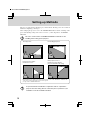
Saving and Retrieving Image Quality Settings (Memory Save)............................ 24
Using the Menu Functions...............................................................................26
Image Menu............................................................................................................26
Signal Menu ...........................................................................................................30
Setup Menu ............................................................................................................31
Info Menu............................................................................................................... 33
Troubleshooting
When Having Some Trouble ...........................................................................36
When the Indicators Provide No Help .............................................................38
Appendices
Maintenance ....................................................................................................46
Cleaning .................................................................................................................46
Replacing Consumables .........................................................................................47
Optional Accessories.......................................................................................51
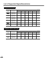
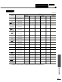
List of Supported Signal Resolutions...............................................................52
Component Video Input.........................................................................................52
Composite Video/S-Video Input............................................................................52
RGB Input ..............................................................................................................53
Specifications ..................................................................................................54
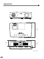
Appearance .....................................................................................................56
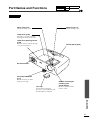
Part Names and Functions ..............................................................................57
Front/Top................................................................................................................57
Control Panel..........................................................................................................58
Rear ........................................................................................................................ 59
Base ........................................................................................................................59
Remote Control ......................................................................................................60
Glossary ..........................................................................................................61
Index................................................................................................................63
Basic Operations
Advanced Operations
TroubleshootingAppendices

2
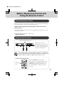
Notes on Handling and Storage
Be sure to observe the following precautions to avoid malfunctions, operating errors or damage to the projector.
Notes on Handling and Storage
• Do not set up the projector near high-voltage electrical wires or sources of magnetic fields.
These may interfere with correct operation.
• Do not touch the lens with bare hands.
If fingerprints or grease get onto the lens, it can interfere with the quality of the projected images. Attach the lens
cover to the lens when the projector is not in use.
• During projection, some points (dots) may appear lit at all times, or they may be dark at all times.
This is caused by the characteristics of the LCD panel, and is not a sign of a malfunction. The LCD panel is
manufactured using extremely high-precision technology. However, black dots may appear on the panel, or some
red, blue or green dots may light extremely brightly at times. Furthermore, sometimes stripe-shaped color
irregularities or brightness irregularities may also appear.
• Remove the batteries from the remote control before storage.
If the batteries are left in the remote control for long periods, they may leak.
• Always attach the lens cap to the lens when not using the projector, to prevent the lens from becoming dirty or
damaged.
• The mercury lamp that is used as the projector's light source deteriorates as a result of normal use and as a
result of impacts or other damage, and may also break with a loud noise, stop working or reach the end of its
service life more quickly.
At such times, the amount of time remaining before the lamp breaks or stops working may vary greatly depending
on the individual lamp characteristics and the operating environment. These are normal characteristics of mercury
lamps. You should always have a spare lamp ready in case it is needed.
• YAMAHA takes no responsibility for loss or damage caused by damage to the projector or operating failures
outside normal service warranty conditions.
Lamp Operating Errors
The mercury lamp that is used as the light source for this projector may stop operating on occasions. This is a normal
characteristic of mercury lamps. If the lamp does not turn on when the projector's power is turned on, remove the
lamp and check if it is broken. If the lamp is not broken, reinstall it. Refer to "Replacing the Lamp" on page 48 of this
manual for instruction on removing and reinstalling the lamp.
If the lamp is broken, replace it with a new lamp. It is recommended that you have a spare lamp ready at all times in
case it is needed.
Notes on Carrying the Projector
• Turn off the projector power and then disconnect the power cord from the electrical outlet.
Furthermore, check that all other cables have been disconnected.
• Attach the lens cap to the lens.
• Retract the adjustable foot.
• If your model of projector has a handle, hold the projector by the handle when carrying it.

3
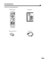
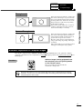
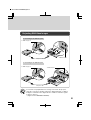
Accessories
Check the included accessories
Remote control Setup guide
Battery LR6 (AA) x 2 Power cord

4
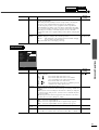
Features of the Projector
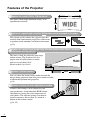
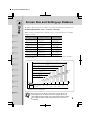
80-inch
screen
Adoption of a wide 1280 x 720 dot panel
This panel allows high-definition images to be
reproduced accurately.
Adoption of a special high-resolution DCDi video circuit developed by Faroudja.
This circuit greatly reduces the jagged edges that
resulted from conventional progressive conversion,
to produce much smoother and natural movement.
(p.30)
Includes 5 picture modes
You can select the desired color mode to match the
images being projected from five preset modes in order
to obtain the optimum image quality.
(p.14)
Includes a variety of color adjustment modes
Various color settings can be adjusted to suit
your preferences, from individual RGB balance
adjustment to setting the color temperature of
your choice. The adjusted settings can then be
stored in memory and recalled at a touch of a
button on the remote control.
(p.24, 25)
Adoption of a short focal-length lens that can project onto 80-inch screens
at distances of 2.5m (8.2 ft.)
This lens is ideal for projecting onto large
indoor screens. The projector can also
project onto 80-inch screens in rooms
with an area of about 10 m
2
.
(Refer to the Setup Guide.)
2.5m
1280
720

5
Basic Operations
This chapter describes basic operations such as turning the projector on and off and adjusting the
projected images.
Turning On the Projector.................................................................. 6
•
••
• Connecting the Power Cord ........................................................................................6
•
••
• Turning On the Power and Projecting Images..........................................................7
Turning Off the Projector.................................................................. 9
Adjusting the Screen Image ........................................................... 11
•
••
• Adjusting the Image Size ...........................................................................................11
•
••
• Adjusting the Image Angle ........................................................................................11
•
••
•
Correcting Keystone Distortion ................................................................................12
•
••
• Displaying a Test Pattern...........................................................................................13
Adjusting the Image Quality........................................................... 14
•
••
• Focusing the Screen Image ........................................................................................14
•
••
• Selecting the picture mode.........................................................................................14
•
••
• Selecting the Image Aspect Ratio..............................................................................15
• Normal mode...................................................................................................................................15
• Squeeze mode..................................................................................................................................16
• Zoom mode .....................................................................................................................................16
• Zoom -Subtitle- mode .....................................................................................................................16
• Through mode .................................................................................................................................17
• Squeeze Through mode...................................................................................................................17
•
••
•
Automatic Adjustment of Computer Images...........................................................17

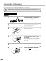
6
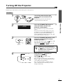
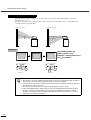
Turning On the Projector
This section describes the procedure from turning on the power to projecting images.
Procedure
1
Check that the power is turned off for
the projector and all components
connected to the projector.
2
Connect the computer or other video
source to the projector.
Refer to the Setup Guide.
3
Remove the lens cap.
4
Connect the accessory power cord to
the projector.
Check that the power cord connector is facing the
same way as the power inlet on the projector, and
then insert the power cord connector securely into
the projector.
5
Connect the other end of the power
cord to a grounded electrical outlet.
6
Turn on the main power switch at the
rear of the projector.
Wait until the indicator lights orange and
the projector goes to the standby condition.
Connecting the Power Cord
Be sure to read the Safety Instructions in this manual for details on safe handling when using
the projector.
Lights orange

7
Basic Operations
Procedure
1
Turn on the power for all equipment
connected to the projector.
For a video source, press the [Play] button at the
video source to start playback if necessary.
Check that the indicator on the projector has
stopped flashing and lights orange.
2
Press the [STANDBY/ON] button on
either the remote control or the
projector's control panel to turn on the
power.
The indicator flashes green, and after a
short period projection starts.
Check that the indicator has stopped
flashing and lights green. (This takes
approximately 15 seconds.)
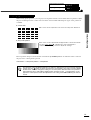
3
If more than one signal source has been connected, use the remote control or
control panel buttons to select the port which the signal source that you
would like to use is connected to, while referring to the following table.
*The display disappears approximately 1 second after the signal is output.
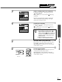
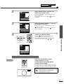
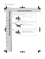
Turning On the Power and Projecting Images
The buttons on the remote control and the projector's control panel cannot be operated
while the indicator is flashing green. Wait until it lights steadily.
The message "No Signal" may appear depending on the projector's menu settings. (p.31)
Port
Button to press
Display at top-right of
screen *
Projector Remote control
INPUT A
[INPUT]
[A]
INPUT A (component) or
INPUT A (RGB)
INPUT B [B]
INPUT B (component) or
INPUT B (RGB)
S VIDEO [S VIDEO] S Video
VIDEO [VIDEO] Video
D4 VIDEO [D4] D4 Video
DVI [DVI] DVI
Lights green
Remote control
Projector
Connecting the Power Cord
Turning On the Power and Projecting Images

Turning On the Projector
8
•
••
•
If only one signal source has been connected, the signals from that source will be
projected without needing to press one of the above buttons.
•
••
•
If video signals are being input to several input ports simultaneously, interference
between the various signals may occur, and this may cause interference in the projected
images. If this happens, turn off the power supply or disconnect the video equipment
which is not currently being used.
•
••
•
If the "No Signal" message does not disappear, check the connections again.
No images will be projected during the time that it takes for signals to be input from the
video source.
•
••
•
If a laptop computer or a computer with an LCD screen has been connected to the
projector, the images may not be projected straight away. After making the connections,
check that the computer has been set up to output signals.
The following table shows examples of how to toggle output settings. For details, refer to
the section of the documentation provided with your computer under a heading such as
"External output", "Connecting an external monitor" or similar.
NEC Panasonic Toshiba IBM Sony Fujitsu Macintosh
[Fn]+[F3] [Fn]+[F3] [Fn]+[F5] [Fn]+[F7] [Fn]+[F7] [Fn]+[F10]
After startup, change the
Control Panel adjustments
so that Mirroring is active.

9
Basic Operations
Turning Off the Projector
Follow the procedure below to turn off the power of the projector.
Procedure
1
Turn off the power for the signal
sources that are connected to the
projector.
Check that the power for all connected
components has been tuned off.
2
Press the [STANDBY/ON] button on
either the remote control or the
projector's control panel.
The confirmation message shown at left will
appear.
If you do not want to turn off the power, press
any button except the [STANDBY/ON] button.
If you do not carry out any operation, the
message will disappear after seven seconds. (The
power will not turn off at this time.)
3
Press the [STANDBY/ON] button on the
projector's control panel or remote
control once more.
The lamp will switch off. The indicator will
flash red and cool-down
will start.
After about 90 seconds, the indicator will
change to flashing orange.
4
Check that the indicator has
changed to light orange.
When the indicator lights orange,
cool-down is complete.
The cool-down period lasts for approximately 5
minutes. (This varies depending on factors such
as the ambient air temperature.)
The cool-down period is a 5 minutes long in
order to allow the heat inside the projector to
dissipate sufficiently.
The buttons on the control panel and
remote control cannot be operated while
the indicator is flashing red. Wait until
the indicator flashes orange (takes
approximately 90 seconds).
Please Press Key Again
To Power Off
Projector
Remote control
Lights orange

Turning Off the Projector
10
5
If not using the projector for long
periods of time, turn off the main power
switch at the rear of the projector.
6
Retract the front adjustable foot if it is
extended.
Turn the front adjustable foot to retract it.
7
Attach the lens cap.
Attach the lens cap to the lens when not using the
projector, in order to stop the lens from getting
dusty or dirty.
Do not turn off the main power switch at the rear of the projector while the cool-down
is in progress. If the main power switch is turned off before cool-down is complete,
wait for the lamp to cool down (normally about one hour is required) before turning
the power back on again. If the power is turned off and on before the lamp has
cooled down, it may result in lamp operating errors.
Refer to "Lamp operating error" on page 36.

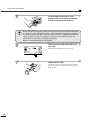
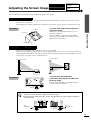
11
Basic Operations
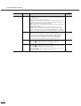
Adjusting the Screen Image
You can adjust the screen image in order to obtain the best possible picture.
The size of the projected image is basically determined by the distance from the projector to the screen.
(Refer to the Setup Guide.)
The following procedures explain how to adjust the screen image once the projector itself has been set up.
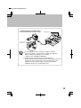
Procedure
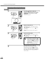
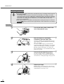
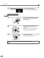
Turn the zoom ring on the projector to
adjust the image.
The image can be enlarged in this way to 1.35
times the normal size.
If you would like to enlarge the image further,
move the projector further away from the screen.
(Refer to the Setup Guide.)
The projector should be as perpendicular to the screen as possible.
If the projector cannot be set up so that it is exactly perpendicular to the screen, it can be set up so that it is
tilting slightly horizontally or vertically. To tilt the projector upward, adjust the front adjustable foot to tilt
the projector at an angle of up to a maximum 12.9°.
Procedure
Turn the front adjustable foot
underneath the projector to adjust the
projector angle.
Turn the front adjustable foot until the desired
projection angle is obtained.
Adjusting the Image Size
Adjusting the Image Angle
•
••
•
When the foot is adjusted, it may cause the projected images to become distorted. Use the
keystone correction function to adjust this distortion. (p.12)
•
••
•
If the projector is tilted horizontally, turn the rear adjustable feet at left and right to adjust the
horizontal angle.
To reduce
To enlarge
Zoom ring
Seen from the side
Seen from above
Extend
Retract
Rear
adjustable foot
Extend
Retract
Retract
Extend
Rear
adjustable foot
Adjusting the Image Size Correcting Keystone
Distortion
Adjusting the Image Angle Displaying a Test
Pattern

Adjusting the Screen Image
12
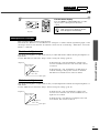
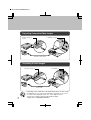
If the projector is set up so that it is at an angle to the screen, a type of distortion known as "keystone
distortion" may occur.
Keystone correction can be carried out if the angle of the projector is within a range of approximately 15°
vertically from the perpendicular.
Procedure
Correcting Keystone Distortion
•
••
•
When keystone correction is carried out, the projected image will become smaller.
•
••
•
The keystone correction settings are memorized, so that if you change the position or angle of
the projector, you may need to readjust the keystone correction settings.
•
••
•
If the images become uneven in appearance after keystone correction is carried out, decrease
the “Sharpness” setting. (p.27, 29)
•
••
•
Keystone correction can also be carried out using the projector menu. (p.31)
•
••
•
If the value displayed in the gauge on the screen stops changing when horizontal or vertical
keystone correction is being carried out, it indicates that the limit for horizontal or vertical
keystone correction has been exceeded. Check that the projector has not been set up at an
angle which exceeds the proper limit.
Approx. 15° above
Approx. 15° below
15°
15°
While holding down the
[SHIFT] button on the
projector's control panel, press
the or button.
Projector Projector

13
Basic Operations
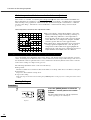
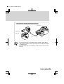
When setting up the projector, you can project a test pattern onto the screen and use this test pattern to adjust
the projected images before a video source has been connected. The following two types of test pattern are
available.
•
••
•
Crosshatch
•
••
•
Grayscale pattern
The test pattern changes as shown below each time the [PATTERN] button on either the remote control or
the projector's control panel is pressed.
Crosshatch → Grayscale pattern → No pattern
Displaying a Test Pattern
The full menu cannot be displayed while a test pattern is being projected. If you need to change a
setting, press the button on either the projector's control panel or the remote control to display
the line menu, and then change the setting. To correct keystone distortion while a test pattern is
being displayed, press and hold the [SHIFT] button and then use the and buttons on the
projector's control panel to make the adjustment. This setting cannot be made using the remote
control.
This can be used to adjust the focus and correct keystone distortion.
This can be used to adjust dark and light shades to the desired shade.
Use the "Color Temp.
", "Flesh Tone" and "Color Balance"
commands in the "Image" menu to adjust the settings.
Adjusting the Image Size Correcting Keystone
Distortion
Adjusting the Image Angle Displaying a Test
Pattern

14
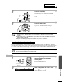
Adjusting the Image Quality
The quality of the screen images can be adjusted as follows.
Procedure
Turn the focus ring to adjust the image
focus.
The following five color modes have been preset for use with images with varying characteristics. You can
use these color modes to obtain the optimum image quality easily, just by selecting whichever color mode
best suits the images. The brightness of the projected images will vary depending on the mode.
Procedure
The picture mode changes as shown
below each time the [PICTURE MODE]
button on the projector's control panel
or the [PICTURE] button on the remote
control is pressed.
A → B → C → PC → sRGB
The current setting appears on the screen each
time the color mode changes.
Focusing the Screen Image
•
••
•
If the surface of the lens is dirty or misted
over as a result of condensation, it may
not be possible to adjust the focus
correctly. If this happens, clean or de-mist
the lens. (p.46)
•
••
•
If the projector is positioned outside the
normal projecting range of 0.9 - 13 m (2.9
- 42.6 ft.), it may not be possible to obtain
the correct focus. If you have trouble
obtaining the correct focus, check the
projection distance.
Selecting the picture mode
Mode name Gamma Color Temp
Priority
element
Use
A Original 1 6700 K
(adjustable)
Color Ideal for enjoying presentations in a natural
atmosphere.
B Original 2 6700 K
(adjustable)
Color Ideal for enjoying presentations such as movies which
have large numbers of dark scenes.
C Original 3 6700 K
(adjustable)
Color Ideal for projecting images with greater modulation
and intensity.
PC 2.2
(Basic)
7500 K
(adjustable)
Brightness Ideal for use in making images as bright as possible
when projecting computer images.
sRGB 2.2
(Basic)
6500 K (fixed) Color Images conform to the sRGB
standard. If the
connected video source has an sRGB mode, set both
the projector and the video source to sRGB.
The color mode setting can also be
changed using the "Picture Mode" item of
the projector's "Image" menu. (p.27, 28)
Focus ring
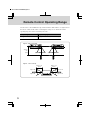
Projector Remote control
Picture B

15
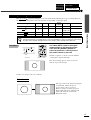
Basic Operations
The aspect ratio for projected images can be selected from the following five types of setting. However,
the aspect ratio settings that can be selected will vary depending on the input signal.
Procedure
For Video (SDTV) signals, the aspect
mode changes in the following order
each time the [ASPECT] button on
either the projector's control panel or
the remote control is pressed.
Normal → Squeeze → Zoom → Zoom -Subtitle-
→ Through → Squeeze Through
The current setting appears on the screen each
time the aspect ratio changes.
Details of each aspect ratio are as follows.
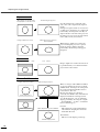
Selecting the Image Aspect Ratio
Input signal Normal Squeeze Zoom
Zoom
-Subtitle-
Through Squeeze Through
Video (SDTV
)
OO O O O O
Video (HDTV )
O- - -
O
(720p only)
-
Computer (SVGA or lower)
O- O - O -
Computer (XGA or higher)
O- O - - -
Do not use the aspect mode function to elongate or compress image that are being projected for
commercial purposes or in public places such as hotel lobbies or stores, as doing so may infringe
the rights of the original copyright owner for the images under copyright protection laws.
Normal mode
Projector
Remote control
Normal
The aspect ratio of the images being input
is maintained, and the images are
projected into a 16:9 screen area.
When 4:3 images are being projected,
black bands will appear at the left and
right of the image as shown in the
illustration at left.
4:3
i
mage
Focusing the
Screen Image
Selecting the Image
Aspect Ratio
Selecting the
Picture Mode
Automatic Adjustment
of Computer Images
Sayfa yükleniyor...
Sayfa yükleniyor...
Sayfa yükleniyor...
Sayfa yükleniyor...
Sayfa yükleniyor...
Sayfa yükleniyor...
Sayfa yükleniyor...
Sayfa yükleniyor...
Sayfa yükleniyor...
Sayfa yükleniyor...
Sayfa yükleniyor...
Sayfa yükleniyor...
Sayfa yükleniyor...
Sayfa yükleniyor...
Sayfa yükleniyor...
Sayfa yükleniyor...
Sayfa yükleniyor...
Sayfa yükleniyor...
Sayfa yükleniyor...
Sayfa yükleniyor...
Sayfa yükleniyor...
Sayfa yükleniyor...
Sayfa yükleniyor...
Sayfa yükleniyor...
Sayfa yükleniyor...
Sayfa yükleniyor...
Sayfa yükleniyor...
Sayfa yükleniyor...
Sayfa yükleniyor...
Sayfa yükleniyor...
Sayfa yükleniyor...
Sayfa yükleniyor...
Sayfa yükleniyor...
Sayfa yükleniyor...
Sayfa yükleniyor...
Sayfa yükleniyor...
Sayfa yükleniyor...
Sayfa yükleniyor...
Sayfa yükleniyor...
Sayfa yükleniyor...
Sayfa yükleniyor...
Sayfa yükleniyor...
Sayfa yükleniyor...
Sayfa yükleniyor...
Sayfa yükleniyor...
Sayfa yükleniyor...
Sayfa yükleniyor...
Sayfa yükleniyor...
Sayfa yükleniyor...
Sayfa yükleniyor...
Sayfa yükleniyor...
Sayfa yükleniyor...
Sayfa yükleniyor...
Sayfa yükleniyor...
Sayfa yükleniyor...
Sayfa yükleniyor...
Sayfa yükleniyor...
Sayfa yükleniyor...
Sayfa yükleniyor...
Sayfa yükleniyor...
-
 1
1
-
 2
2
-
 3
3
-
 4
4
-
 5
5
-
 6
6
-
 7
7
-
 8
8
-
 9
9
-
 10
10
-
 11
11
-
 12
12
-
 13
13
-
 14
14
-
 15
15
-
 16
16
-
 17
17
-
 18
18
-
 19
19
-
 20
20
-
 21
21
-
 22
22
-
 23
23
-
 24
24
-
 25
25
-
 26
26
-
 27
27
-
 28
28
-
 29
29
-
 30
30
-
 31
31
-
 32
32
-
 33
33
-
 34
34
-
 35
35
-
 36
36
-
 37
37
-
 38
38
-
 39
39
-
 40
40
-
 41
41
-
 42
42
-
 43
43
-
 44
44
-
 45
45
-
 46
46
-
 47
47
-
 48
48
-
 49
49
-
 50
50
-
 51
51
-
 52
52
-
 53
53
-
 54
54
-
 55
55
-
 56
56
-
 57
57
-
 58
58
-
 59
59
-
 60
60
-
 61
61
-
 62
62
-
 63
63
-
 64
64
-
 65
65
-
 66
66
-
 67
67
-
 68
68
-
 69
69
-
 70
70
-
 71
71
-
 72
72
-
 73
73
-
 74
74
-
 75
75
-
 76
76
-
 77
77
-
 78
78
-
 79
79
-
 80
80


Yamaha LPX-500 Kullanım kılavuzu
- Kategori
- Projektörler
- Tip
- Kullanım kılavuzu
diğer dillerde
- español: Yamaha LPX-500 Manual de usuario
- français: Yamaha LPX-500 Manuel utilisateur
- italiano: Yamaha LPX-500 Manuale utente
- svenska: Yamaha LPX-500 Användarmanual
- čeština: Yamaha LPX-500 Uživatelský manuál
- polski: Yamaha LPX-500 Instrukcja obsługi
- Deutsch: Yamaha LPX-500 Benutzerhandbuch
- português: Yamaha LPX-500 Manual do usuário
- English: Yamaha LPX-500 User manual
- dansk: Yamaha LPX-500 Brugermanual
- русский: Yamaha LPX-500 Руководство пользователя
- suomi: Yamaha LPX-500 Ohjekirja
- Nederlands: Yamaha LPX-500 Handleiding
- română: Yamaha LPX-500 Manual de utilizare
