Hitachi DH 40MRY Handling Instructions Manual
- Kategori
- Döner çekiçler
- Tip
- Handling Instructions Manual
Bu kılavuz aynı zamanda aşağıdakiler için de uygundur:

DH 40MRY
Rotary Hammer
Bohrhammer
™Ê˘ÚÔ‰Ú··ÓÔ ÂÚȘÙÚÔÊÈÎÔ
Młotowiertarka
Fúrókalapács
Vrtací kladivo
Kırıcı Delici
KoÏÄËÌËpoÇaÌÌêÈ ÔepÙopaÚop
1
Read through carefully and understand these instructions before use.
Diese Anleitung vor Benutzung des Werkzeugs sorgfältig durchlesen und verstehen.
¢È·‚¿ÛÙ ÚÔÛÂÎÙÈο Î·È Î·Ù·ÓÔ‹ÛÂÙ ·˘Ù¤˜ ÙȘ Ô‰ËÁ›Â˜ ÚÈÓ ÙË ¯Ú‹ÛË.
Przed użytkowaniem należy dokładnie przeczytać niniejszą instrukcję i zrozumieć jej treść.
Használat előtt olvassa el figyelmesen a használati utasítást.
Před použitím si pečlivě přečtěte tento návod a ujistěte se, že mu dobře rozumíte.
Aleti kullanmadan önce bu kılavuzu iyice okuyun ve talimatları anlayın.
BÌËÏaÚeÎëÌo ÔpoäÚËÚe ÀaÌÌyï ËÌcÚpyÍáËï Ôo íÍcÔÎyaÚaáËË ÔpeÊÀe äeÏ ÔoÎëÁoÇaÚëcÓ ËÌcÚpyÏeÌÚoÏ.
606
Code No. C99153391 N
Printed in Japan
Handling instructions
Bedienungsanleitung
√‰ËÁ›Â˜ ¯ÂÈÚÈÛÌÔ‡
Instrukcja obsługi
Kezelési utasítás
Návod k obsluze
Kullanım talimatları
àÌcÚpyÍáËÓ Ôo íÍcÔÎyaÚaáËË
Hitachi Koki Co., Ltd.
Representative office in Europe
Hitachi Power Tools Europe GmbH
Siemensring 34, 47877 Willich 1, F. R. Germany
Head office in Japan
Hitachi Koki Co., Ltd.
Shinagawa Intercity Tower A, 15-1, Konan 2-chome,
Minato-ku, Tokyo, Japan
30. 6. 2006
K. Kato
Board Director
Magyar
EU MEGFELELŐSÉGI NYILATKOZAT
Teljes felelősségünk tudatában kijelentjük, hogy ez a termék
megfelel az EN60745, EN55014, és EN 61000-3
szabványoknak illetve szabványosított dokumentumoknak,
az Európa Tanács 73/23/EEC, 89/336/EEC, és 98/37/EC
Tanácsi Direktíváival összhangban.
Jelen nyilatkozat a terméken feltüntetett CE jelzésre
vonatkozik.
Čeština
PROHLÁŠENÍ O SHODĚ S CE
Prohlašujeme na svoji zodpovědnost, že tento výrobek
odpovídá normám EN60745, EN55014 a EN61000-3 v
souladu se směrnicemi 73/23/EEC, 89/336/EEC a 98/37/EC.
Toto prohlášení platí pro výrobek označený značkou CE.
Türkçe
AB UYGUNLUK BEYANI
Bu ürünün, 73/23/EEC, 89/336/EEC ve 98/37/EC sayılı
Konsey Direktiflerine uygun olarak, EN60745, EN55014 ve
EN61000-3 sayılı standartlara ve standartlaßtırılmıß belgelere
uygun olduåunu, tamamen kendi sorumluluåumuz altında
beyan ederiz.
Bu beyan, üzerinde CE ißareti bulunan ürünler için
geçerlidir.
PyccÍËÈ
ÑEKãAPAñàü COOTBETCTBàü EC
Mê c ÔoÎÌoÈ oÚÇeÚcÚÇeÌÌocÚëï ÁaÓÇÎÓeÏ, äÚo ÀaÌÌoe
ËÁÀeÎËe cooÚÇeÚcÚÇyeÚ cÚaÌÀapÚaÏ ËÎË
cÚaÌÀapÚËÁoÇaÌÌêÏ ÀoÍyÏeÌÚaÏ EN60745, EN55014 Ë
EN61000-3 coÖÎacÌo ÑËpeÍÚËÇaÏ CoÇeÚa 73/23/EEC, 89/
336/EEC Ë 98/37/EC.
ÑaÌÌaÓ ÀeÍÎapaáËÓ oÚÌocËÚcÓ Í ËÁÀeÎËÓÏ, Ìa ÍoÚopêx
ËÏeeÚcÓ ÏapÍËpoÇÍa CE.
English
EC DECLARATION OF CONFORMITY
We declare under our sole responsibility that this
product is in conformity with standards or standardized
documents EN60745, EN55014 and EN61000-3 in
accordance with Council Directives 73/23/EEC, 89/336/
EEC and 98/37/EC.
This declaration is applicable to the product affixed CE
marking.
Deutsch
ERKLÄRUNG ZUR KONFORMITÄT MIT CE-REGELN
Wir erklären mit alleiniger Verantwortung, daß dieses
Produkt den Standards oder standardisierten
Dokumenten EN60745, EN55014 und EN61000-3 in
Übereinstimmung mit den Direktiven des Europarats
73/23/EWG, 89/336/EWG und 98/37/CE entspricht.
Diese Erklärung gilt für Produkte, die die CE-Markierung
tragen.
Ελληνικά
EK ∆ΗΛ·ΣΗ ΕΝΑΡΜΝΙΣΜΥ
∆ηλώνυµε µε απλυτη υπευθυντητα τι αυτ τ
πριν είναι εναρµνισµέν µε τα πρτυπα ή τα
έγρα#α πρτύπων EN60745, EN55014 και EN61000-3
σε συµ#ωνία µε τις δηγίες τυ Συµ(υλίυ 73/23/
EOK, 89/336/EOK και 98/37/EK.
Αυτή η δήλωση ισ)ύει στ πριν µε τ σηµάδι CE.
Polski
DEKLARACJA ZGODNOŚCI Z EC
Oznajmiamy z całkowitą odpowiedzialnością, że produkt
ten pozostaje w zgodzie ze standardami lub standardową
formą dokumentów EN60745, EN55014 i EN61000-3 w
zgodzie z Zasadami Rady 73/23/EEC 89/336/ EEC i 98/
37/EC.
To oświadczenie odnosi się do załączonego produktu z
oznaczeniami CE.
3
6
9
12
2
5
8
11
1
4
7
10
E
5
3
4
6
7
0
9
8
9
0
8
8
0
9
6
B
A
D
C
2
1

2
3
60
English Deutsch ∂ÏÏËÓÈο Polski
1
2
3
4
5
6
7
8
9
0
A
B
C
D
E
F
G
H
I
J
K
L
M
N
O
P
Q
Tool shank
Grease
Tool
Part of SDS max shank
Front cap
Grip
Dial
Button
Selector lever
Lever holder
Stopper
Side handle
Taper shank adapter
Drill bit (taper shank)
Indicating groove shows
standard depth matching
the outside diameter of
the anchor for drilling.
Cotter
Rest
Drill chuck
Chuck adapter
Core bit
Core bit shank
Guide plate
Center pin
Core bit tip
Crank cover
Wear limit
No. of Carbon Brush
Werkzeugschaft
Schmierfett
Werkzeug
Teii des SDS-max
Schaftes
Vordere Abdeckung
Spannbacke
Skalenscheibe
Knopf
Wahlhebel
Hebelhalter
Anschlagstange
Seitengriff
Konusschaftadapter
Bohren (mit konischem
Schaft)
Anzeigerille zeigt
Normalloch-tiefe gemäß
Außendurchmesser des
Ankers für Bohren.
Keil
Auflage
Bohrfutter
Bohrfutteradapter
Bohrkrone
Bohrkronenschenkel
Führengsplatte
Mittelstift
Bohrkronenspitze
Kurbelabdeckung
Verschleißgrenze
Nr. der Kohlebürste
™Ù¤Ï¯Ԙ ÂÚÁ·Ï›Ԣ
°Ú¿ÛÔ
∂ÚÁ·Ï›Ô
∆Ì‹Ì· ÙÔ˘ ÛÙÂϤ¯Ô˘˜
SDS max
ªÚÔÛÙÈÓfi ÂÚ›‚ÏËÌ·
§·‚‹
∫·ÓÙÚ¿Ó
∫Ô˘Ì›
ªÔ¯Ïfi˜ ÂÈÏÔÁ‹˜
™Ù‹ÚÈÁÌ· ÌÔ¯ÏÔ‡
™ÙfiÂÚ
¶Ï¢ÚÈ΋ Ï·‚‹
∫ˆÓÈÎfi˜ ÚÔÛ·ÚÌÔÁ¤·˜
ÛÙÂϤ¯Ô˘˜
§Â›‰· ÙÚ˘·ÓÈÔ‡
∏ ÂÓ‰ÂÈÎÙÈ΋ ·˘Ï¿ÎˆÛË
‰Â›¯ÓÂÈ ÙÔ Î·ÓÔÓÈÎfi
‚¿ıÔ˜ Ô˘ Ù·ÈÚÈ¿˙ÂÈ ÛÙËÓ
Â͈ÙÂÚÈ΋ ‰È¿ÌÂÙÚÔ ÙÔ˘
¿ÁÎÈÛÙÚÔ˘ ÁÈ· ÙÚ‡ËÌ·.
∫fiÊÙ˘
™Ù‹ÚÈÁÌ·
™ÊÈÎÙ‹Ú·˜ ÙÚ˘·ÓÈÔ‡
¶ÚÔÛ·ÚÌÔÁ¤·˜ ÛÊÈÎÙ‹Ú·
∫˘ÏÈÓ‰ÚÈÎfi ÎÔÙÈÎfi ÙÌ‹Ì·
ÕÍÔÓ·˜ ΢ÏÈÓ‰ÚÈÎÔ‡
ÎÔÙÈÎÔ‡ ÙÌ‹Ì·ÙÔ˜
√‰ËÁËÙÈ΋ Ͽη
∫ÂÓÙÚÈ΋ ÂÚfiÓË
ÕÎÚË Î˘ÏÈÓ‰ÚÈÎÔ‡
ÎÔÙÈÎÔ‡ ÙÌ‹Ì·ÙÔ˜
∫¿Ï˘ÌÌ· ÛÙÚÔÊ¿ÏÔ˘
ŸÚÈÔ ÊıÔÚ¿˜
∞Ú. ηڂԢӷΛˆÓ
Uchwyt narzędzia
Smar
Narzędzie
Część uchwytu wiertła
samomocującego SDS max
Przednia pokrywa
Uchwyt
Pokrętło
Przycisk
Dźwignia nastawcza
Uchwyt dźwigni
Zatyczka
Uchwyt boczny
Adaptor uchwytu
stożkowego
Wiertło (uchwyt stożkowy)
Nacięcie wyznacza
Standardową głębokość
równą zewnętrznej
średnicy zaczepu
wiercenia.
Sworzeń
Oparcie
Uchwyt wiertarski
Adaptor uchwytu
Koronka rdzeniowa
Trzon koronki rdzeniowej
Płyta wiodąca
Sworzeń centrujący
Końcówka koronki
rdzeniowej
Pokrywa korby
Granica zużycia
Nr szczotki węglowej
English
Only for EU countries
Do not dispose of electric tools together with
household waste material!
In observance of European Directive 2002/96/EC
on waste electrical and electronic equipment and
its implementation in accordance with national
law, electric tools that have reached the end of
their life must be collected separately and returned
to an environmentally compatible recycling
facility.
Deutsch
Nur für EU-Länder
Werfen Sie Elektrowerkzeuge nicht in den
Hausmüll!
Gemäss Europäischer Richtlinie 2002/96/EG über
Elektro- und Elektronik- Altgeräte und Umsetzung
in nationales Recht müssen verbrauchte
Elektrowerkzeuge getrennt gesammelt und einer
umweltgerechten Wiederververtung zugeführt
werden.
EÏÏËvÈο
Mfivo ÁÈ· ÙȘ ¯ÒÚ˜ Ù˘ EE
MËv Âٿ٠ٷ ËÏÂÎÙÚÈο ÂÚÁ·Ï›· ÛÙov ο‰o
oÈÎÈ·ÎÒv ·oÚÚÈÌÌ¿Ùˆv!
™‡Ìʈv· Ì ÙËv ÂuÚˆ·˚΋ o‰ËÁ›· 2002/96/EK ÂÚ›
ËÏÂÎÙÚÈÎÒv Î·È ËÏÂÎÙÚovÈÎÒv ÛuÛÎÂuÒv Î·È ÙËv
Âvۈ̿وۋ Ù˘ ÛÙo ÂıvÈÎfi ‰›Î·Èo, Ù· ËÏÂÎÙÚÈο
ÂÚÁ·Ï›· Ú¤ÂÈ v· ÛuÏϤÁovÙ·È Í¯ˆÚÈÛÙ¿ Î·È v·
ÂÈÛÙÚ¤ÊovÙ·È ÁÈ· ·v·Î‡ÎψÛË Ì ÙÚfio ÊÈÏÈÎfi Úo˜
Ùo ÂÚÈ‚¿ÏÏov.
Polski
Dotyczy tylko państw UE
Nie wyrzucaj elektronarzędzi wraz z odpadami z
gospodarstwa domowego!
Zgodnie z Europejską Dyrektywą 2002/96/WE w
sprawie zużytego sprzętu elektrotechnicznego i
elektronicznego oraz dostosowaniem jej do prawa
krajowego, zużyte elektronarzędzia należy
posegregować i zutylizować w sposób przyjazny dla
środowiska.
Magyar
Csak EU-országok számára
Az elektromos kéziszerszámokat ne dobja a háztartási
szemétbe!
A használt villamos és elektronikai készülékekről szóló
2002/96/EK irányelv és annak a nemzeti jogba való
átültetése szerint az elhasznált elektromos
kéziszerszámokat külön kell gyűjteni, és
környezetbarát módon újra kell hasznosítani.
Čeština
Jen pro státy EU
Elektrické nářadí nevyhazujte do komunálního
odpadu!
Podle evropské směrnice 2002/96/EG o nakládání s
použitými elektrickými a elektronickými zařízeními a
odpovídajících ustanovení právních předpisů
jednotlivých zemí se použitá elektrická nářadí musí
sbírat odděleně od ostatního odpadu a podrobit
ekologicky šetrnému recyklování.
Türkçe
Sadece AB ülkeleri için
Elektrikli el aletlerini evdeki çöp kutusuna atmayınız!
Kullanılmıß elektrikli aletleri, elektrik ve elektronikli eski
cihazlar hakkındaki 2002/96/EC Avrupa yönergelerine
göre ve bu yönergeler ulusal hukuk kurallarına göre
uyarlanarak, ayrı olarak toplanmalı ve çevre ßartlarına
uygun bir ßekilde tekrar deåerlendirmeye
gönderilmelidir.
PyccÍËÈ
ToÎëÍo ÀÎÓ cÚpaÌ EC
He ÇêÍËÀêÇaÈÚe íÎeÍÚpoÔpËÄopê ÇÏecÚe c
oÄoêäÌêÏ ÏycopoÏ!
B cooÚÇeÚcÚÇËË c eÇpoÔeÈcÍoÈ ÀËpeÍÚËÇoÈ 2002/
96/EG oÄ yÚËÎËÁaáËË cÚapêx íÎeÍÚpËäecÍËx Ë
íÎeÍÚpoÌÌêx ÔpËÄopoÇ Ë Ç cooÚÇeÚcÚÇËË c
ÏecÚÌêÏË ÁaÍoÌaÏË íÎeÍÚpoÔpËÄopê, ÄêÇçËe Ç
íÍcÔÎyaÚaáËË, ÀoÎÊÌê yÚËÎËÁoÇêÇaÚëcÓ
oÚÀeÎëÌo ÄeÁoÔacÌêÏ ÀÎÓ oÍpyÊaïçeÈ cpeÀê
cÔocoÄoÏ.
13
16
19
14
17
20
15
18
21
J
K
J
M
L
J
K
22
C
F
G
73
17 mm
7 mm
P
H
I
4
5
6
N
J
K
O
Q

2
3
60
English Deutsch ∂ÏÏËÓÈο Polski
1
2
3
4
5
6
7
8
9
0
A
B
C
D
E
F
G
H
I
J
K
L
M
N
O
P
Q
Tool shank
Grease
Tool
Part of SDS max shank
Front cap
Grip
Dial
Button
Selector lever
Lever holder
Stopper
Side handle
Taper shank adapter
Drill bit (taper shank)
Indicating groove shows
standard depth matching
the outside diameter of
the anchor for drilling.
Cotter
Rest
Drill chuck
Chuck adapter
Core bit
Core bit shank
Guide plate
Center pin
Core bit tip
Crank cover
Wear limit
No. of Carbon Brush
Werkzeugschaft
Schmierfett
Werkzeug
Teii des SDS-max
Schaftes
Vordere Abdeckung
Spannbacke
Skalenscheibe
Knopf
Wahlhebel
Hebelhalter
Anschlagstange
Seitengriff
Konusschaftadapter
Bohren (mit konischem
Schaft)
Anzeigerille zeigt
Normalloch-tiefe gemäß
Außendurchmesser des
Ankers für Bohren.
Keil
Auflage
Bohrfutter
Bohrfutteradapter
Bohrkrone
Bohrkronenschenkel
Führengsplatte
Mittelstift
Bohrkronenspitze
Kurbelabdeckung
Verschleißgrenze
Nr. der Kohlebürste
™Ù¤Ï¯Ԙ ÂÚÁ·Ï›Ԣ
°Ú¿ÛÔ
∂ÚÁ·Ï›Ô
∆Ì‹Ì· ÙÔ˘ ÛÙÂϤ¯Ô˘˜
SDS max
ªÚÔÛÙÈÓfi ÂÚ›‚ÏËÌ·
§·‚‹
∫·ÓÙÚ¿Ó
∫Ô˘Ì›
ªÔ¯Ïfi˜ ÂÈÏÔÁ‹˜
™Ù‹ÚÈÁÌ· ÌÔ¯ÏÔ‡
™ÙfiÂÚ
¶Ï¢ÚÈ΋ Ï·‚‹
∫ˆÓÈÎfi˜ ÚÔÛ·ÚÌÔÁ¤·˜
ÛÙÂϤ¯Ô˘˜
§Â›‰· ÙÚ˘·ÓÈÔ‡
∏ ÂÓ‰ÂÈÎÙÈ΋ ·˘Ï¿ÎˆÛË
‰Â›¯ÓÂÈ ÙÔ Î·ÓÔÓÈÎfi
‚¿ıÔ˜ Ô˘ Ù·ÈÚÈ¿˙ÂÈ ÛÙËÓ
Â͈ÙÂÚÈ΋ ‰È¿ÌÂÙÚÔ ÙÔ˘
¿ÁÎÈÛÙÚÔ˘ ÁÈ· ÙÚ‡ËÌ·.
∫fiÊÙ˘
™Ù‹ÚÈÁÌ·
™ÊÈÎÙ‹Ú·˜ ÙÚ˘·ÓÈÔ‡
¶ÚÔÛ·ÚÌÔÁ¤·˜ ÛÊÈÎÙ‹Ú·
∫˘ÏÈÓ‰ÚÈÎfi ÎÔÙÈÎfi ÙÌ‹Ì·
ÕÍÔÓ·˜ ΢ÏÈÓ‰ÚÈÎÔ‡
ÎÔÙÈÎÔ‡ ÙÌ‹Ì·ÙÔ˜
√‰ËÁËÙÈ΋ Ͽη
∫ÂÓÙÚÈ΋ ÂÚfiÓË
ÕÎÚË Î˘ÏÈÓ‰ÚÈÎÔ‡
ÎÔÙÈÎÔ‡ ÙÌ‹Ì·ÙÔ˜
∫¿Ï˘ÌÌ· ÛÙÚÔÊ¿ÏÔ˘
ŸÚÈÔ ÊıÔÚ¿˜
∞Ú. ηڂԢӷΛˆÓ
Uchwyt narzędzia
Smar
Narzędzie
Część uchwytu wiertła
samomocującego SDS max
Przednia pokrywa
Uchwyt
Pokrętło
Przycisk
Dźwignia nastawcza
Uchwyt dźwigni
Zatyczka
Uchwyt boczny
Adaptor uchwytu
stożkowego
Wiertło (uchwyt stożkowy)
Nacięcie wyznacza
Standardową głębokość
równą zewnętrznej
średnicy zaczepu
wiercenia.
Sworzeń
Oparcie
Uchwyt wiertarski
Adaptor uchwytu
Koronka rdzeniowa
Trzon koronki rdzeniowej
Płyta wiodąca
Sworzeń centrujący
Końcówka koronki
rdzeniowej
Pokrywa korby
Granica zużycia
Nr szczotki węglowej
English
Only for EU countries
Do not dispose of electric tools together with
household waste material!
In observance of European Directive 2002/96/EC
on waste electrical and electronic equipment and
its implementation in accordance with national
law, electric tools that have reached the end of
their life must be collected separately and returned
to an environmentally compatible recycling
facility.
Deutsch
Nur für EU-Länder
Werfen Sie Elektrowerkzeuge nicht in den
Hausmüll!
Gemäss Europäischer Richtlinie 2002/96/EG über
Elektro- und Elektronik- Altgeräte und Umsetzung
in nationales Recht müssen verbrauchte
Elektrowerkzeuge getrennt gesammelt und einer
umweltgerechten Wiederververtung zugeführt
werden.
EÏÏËvÈο
Mfivo ÁÈ· ÙȘ ¯ÒÚ˜ Ù˘ EE
MËv Âٿ٠ٷ ËÏÂÎÙÚÈο ÂÚÁ·Ï›· ÛÙov ο‰o
oÈÎÈ·ÎÒv ·oÚÚÈÌÌ¿Ùˆv!
™‡Ìʈv· Ì ÙËv ÂuÚˆ·˚΋ o‰ËÁ›· 2002/96/EK ÂÚ›
ËÏÂÎÙÚÈÎÒv Î·È ËÏÂÎÙÚovÈÎÒv ÛuÛÎÂuÒv Î·È ÙËv
Âvۈ̿وۋ Ù˘ ÛÙo ÂıvÈÎfi ‰›Î·Èo, Ù· ËÏÂÎÙÚÈο
ÂÚÁ·Ï›· Ú¤ÂÈ v· ÛuÏϤÁovÙ·È Í¯ˆÚÈÛÙ¿ Î·È v·
ÂÈÛÙÚ¤ÊovÙ·È ÁÈ· ·v·Î‡ÎψÛË Ì ÙÚfio ÊÈÏÈÎfi Úo˜
Ùo ÂÚÈ‚¿ÏÏov.
Polski
Dotyczy tylko państw UE
Nie wyrzucaj elektronarzędzi wraz z odpadami z
gospodarstwa domowego!
Zgodnie z Europejską Dyrektywą 2002/96/WE w
sprawie zużytego sprzętu elektrotechnicznego i
elektronicznego oraz dostosowaniem jej do prawa
krajowego, zużyte elektronarzędzia należy
posegregować i zutylizować w sposób przyjazny dla
środowiska.
Magyar
Csak EU-országok számára
Az elektromos kéziszerszámokat ne dobja a háztartási
szemétbe!
A használt villamos és elektronikai készülékekről szóló
2002/96/EK irányelv és annak a nemzeti jogba való
átültetése szerint az elhasznált elektromos
kéziszerszámokat külön kell gyűjteni, és
környezetbarát módon újra kell hasznosítani.
Čeština
Jen pro státy EU
Elektrické nářadí nevyhazujte do komunálního
odpadu!
Podle evropské směrnice 2002/96/EG o nakládání s
použitými elektrickými a elektronickými zařízeními a
odpovídajících ustanovení právních předpisů
jednotlivých zemí se použitá elektrická nářadí musí
sbírat odděleně od ostatního odpadu a podrobit
ekologicky šetrnému recyklování.
Türkçe
Sadece AB ülkeleri için
Elektrikli el aletlerini evdeki çöp kutusuna atmayınız!
Kullanılmıß elektrikli aletleri, elektrik ve elektronikli eski
cihazlar hakkındaki 2002/96/EC Avrupa yönergelerine
göre ve bu yönergeler ulusal hukuk kurallarına göre
uyarlanarak, ayrı olarak toplanmalı ve çevre ßartlarına
uygun bir ßekilde tekrar deåerlendirmeye
gönderilmelidir.
PyccÍËÈ
ToÎëÍo ÀÎÓ cÚpaÌ EC
He ÇêÍËÀêÇaÈÚe íÎeÍÚpoÔpËÄopê ÇÏecÚe c
oÄoêäÌêÏ ÏycopoÏ!
B cooÚÇeÚcÚÇËË c eÇpoÔeÈcÍoÈ ÀËpeÍÚËÇoÈ 2002/
96/EG oÄ yÚËÎËÁaáËË cÚapêx íÎeÍÚpËäecÍËx Ë
íÎeÍÚpoÌÌêx ÔpËÄopoÇ Ë Ç cooÚÇeÚcÚÇËË c
ÏecÚÌêÏË ÁaÍoÌaÏË íÎeÍÚpoÔpËÄopê, ÄêÇçËe Ç
íÍcÔÎyaÚaáËË, ÀoÎÊÌê yÚËÎËÁoÇêÇaÚëcÓ
oÚÀeÎëÌo ÄeÁoÔacÌêÏ ÀÎÓ oÍpyÊaïçeÈ cpeÀê
cÔocoÄoÏ.
13
16
19
14
17
20
15
18
21
J
K
J
M
L
J
K
22
C
F
G
73
17 mm
7 mm
P
H
I
4
5
6
N
J
K
O
Q

4
Magyar Čeština Türkçe PyccÍËÈ
1
2
3
4
5
6
7
8
9
0
A
B
C
D
E
F
G
H
I
J
K
L
M
N
O
P
Q
Szerszámszár
Zsír
Szerszám
SDS max szár része
Elülső kupak
Karmantyú
Szabályzó
Retesz
Üzemmód váltó
Üzemmódok
Ütköző
Oldalfogantyú
Kónuszos szár adapter
Fúróhegy (kónuszos szárú)
A jelzőhorony a rögzítő
horgonybetét külső
átmérőjének megfelelő
standard furatmélységet
jelzi.
Ék
Alátámasztó blokk
Fúrótokmány
Tokmány adapter
Magfúró korona
Magfúró korona szára
Vezetőlap
Központosító tüske
Magfúró korona vágóéle
Hajtómű burkolata
Kopási határ
Szénkefe száma
Stopka vrtáku
Vazelína
Nástroj
Část SDS max stopky
Přední kryt
Držadlo
Číselník
Tlačítko
Volicí páčka
Držák páčky
Zarážka
Boční držadlo
Adaptér pro kuželovou
stopku
Vrták s kuželovou stopkou
Žlábek ukazuje standardní
hloubku odpovídající
vnějšímu průměru vrtací
šablony.
Závlačka
Klidová poloha
Sklíčidlo
Adaptér sklíčidla
Okružní dutý vrták
Stopka pro středový vrták
Šablona
Středový vrták
Hrot středového vrtáku
Kryt převodovky
Mez opotřebení
Číslo uhlíkového kartáčku
Takım sapı
Gres
Takım
SDS max sapı parçası
Ön mandren kapaåı
Mandren tutma yeri
Kadran
Düåme
Seçici kol
Kol tutucu
Derinlik mesnedi
Yan kol
Konik sap adaptörü
Matkap ucu (konik saplı)
Kılavuz yiv, delme
ankrajının dıß çapına eßit
olan standart derinliåi
gösterir.
Kama
Destekler
Ek Mandren
Mandren adaptörü
Buat ucu
Buat ucu sapı
Kılavuz plakası
Merkez pimi
Buat ucu
Krank kapaåı
Yıpranma limiti
Kömür numarası
CÚepÊeÌë ËÌcÚpyÏeÌÚa
CÏaÁÍa
àÌcÚpyÏeÌÚ
CaÏoÁaÇËÌäËÇaïçaÓcÓ
äacÚë cÚepÊÌÓ
èepeÀÌËÈ ÔaÚpoÌ
PyÍoÓÚÍa
ÑËcÍ
KÌoÔÍa
PêäaÖ ÔepeÍÎïäaÚeÎÓ
PyÍoÓÚÍa pêäaÖa
CÚoÔop
ÅoÍoÇaÓ pyÍoÓÚÍa
KoÌycooÄpaÁÌaÓ ÌacaÀÍa
cÚepÊÌÓ ËÌcÚpyÏeÌÚa
PaÄoäaÓ ÔoÇepxÌocÚë
cÇepÎa (ÍoÌycooÄpaÁÌaÓ
äacÚë cÚepÊÌÓ)
àÌÀËÍaÚopÌaÓ ÄopoÁÀÍa
ÔoÍaÁêÇaeÚ
cÚaÌÀapÚÌyï ÖÎyÄËÌy,
cooÚÇeÚcÚÇyïçyï
ÇÌeåÌeÏy ÀËaÏeÚpy
aÌÍepa ÀÎÓ cÇepÎeÌËÓ.
KÎËÌ
èoÀcÚaÇÍa
ÂaÊËÏÌêÈ ÔaÚpoÌ cÇepÎa
HacaÀÍa ÁaÊËÏÌoÖo
ÔaÚpoÌa
ãeÁÇËe Äypa
CÚepÊeÌë ÎeÁÇËÓ Äypa
HaÔpaÇÎÓïçaÓ ÔÎacÚËÌa
ñeÌÚpoÇoäÌêÈ åÚoÍ
HaÍoÌeäÌËÍ ÎeÁÇËÓ Äypa
KpêåÍa ÍopoÄÍË pêäaÖa
èpeÀeÎ ËÁÌoca
£ yÖoÎëÌoÈ çeÚÍË
00Table_DH40MRY_EE 13/6/06, 18:024

5
English
GENERAL SAFETY RULES
WARNING!
Read all instructions
Failure to follow all instructions listed below may result in
electric shock, fire and/or serious injury.
The term “power tool” in all of the warnings listed below
refers to your mains operated (corded) power tool or battery
operated (cordless) power tool.
SAVE THESE INSTRUCTIONS
1) Work area
a) Keep work area clean and well lit.
Cluttered and dark areas invite accidents.
b) Do not operate power tools in explosive
atmospheres, such as in the presence of flammable
liquids, gases or dust.
Power tools create sparks which may ignite the
dust of fumes.
c) Keep children and bystanders away while operating
a power tool.
Distractions can cause you to lose control.
2) Electrical safety
a) Power tool plugs must match the outlet.
Never modify the plug in any way.
Do not use any adapter plugs with earthed
(grounded) power tools.
Unmodified plugs and matching outlets will reduce
risk of electric shock.
b) Avoid body contact with earthed or grounded
surfaces such as pipes, radiators, ranges and
refrigerators.
There is an increased risk of electric shock if your
body is earthed or grounded.
c) Do not expose power tools to rain or wet
conditions.
Water entering a power tool will increase the risk
of electric shock.
d) Do not abuse the cord. Never use the cord for
carrying, pulling or unplugging the power tool.
Keep cord away from heat, oil, sharp edges or
moving parts.
Damaged or entangled cords increase the risk of
electric shock.
e) When operating a power tool outdoors, use an
extension cord suitable for outdoor use.
Use of a cord suitable for outdoor use reduces
the risk of electric shock
3) Personal safety
a) Stay alert, watch what you are doing and use
common sense when operating a power tool.
Do not use a power tool while you are tired or
under the influence of drugs, alcohol or medication.
A moment of inattention while operating power
tools may result in serious personal injury.
b) Use safety equipment. Always wear eye protection.
Safety equipment such as dust mask, non-skid
safety shoes, hard hat, or hearing protection used
for appropriate conditions will reduce personal
injuries.
c) Avoid accidental starting. Ensure the switch is in
the off position before plugging in.
Carrying power tools with your finger on the
switch or plugging in power tools that have the
switch on invites accidents.
d) Remove any adjusting key or wrench before
turning the power tool on.
A wrench or a key left attached to a rotating part
of the power tool may result in personal injury.
e) Do not overreach. Keep proper footing and balance
at all times.
This enables better control of the power tool in
unexpected situations.
f) Dress properly. Do not wear loose clothing or
jewellery. Keep your hair, clothing and gloves
away from moving parts.
Loose clothes, jewellery or long hair can be caught
in moving parts.
g) If devices are provided for the connection of dust
extraction and collection facilities, ensure these
are connected and properly used.
Use of these devices can reduce dust related hazards.
4) Power tool use and care
a) Do not force the power tool. Use the correct
power tool for your application.
The correct power tool will do the job better and
safer at the rate for which it was designed.
b) Do not use the power tool if the switch does not
turn it on and off.
Any power tool that cannot be controlled with the
switch is dangerous and must be repaired.
c) Disconnect the plug from the power source before
making any adjustments, changing accessories, or
storing power tools.
Such preventive safety measures reduce the risk
of starting the power tool accidentally.
d) Store idle power tools out of the reach of children
and do not allow persons unfamiliar with the
power tool or these instructions to operate the
power tool.
Power tools are dangerous in the hands of
untrained users.
e) Maintain power tools. Check for misalignment or
binding of moving parts, breakage of parts and
any other condition that may affect the power
tools operation.
If damaged, have the power tool repaired before
use.
Many accidents are caused by poorly maintained
power tools.
f) Keep cutting tools sharp and clean.
Properly maintained cutting tools with sharp cutting
edges are less likely to bind and are easier to
control.
g) Use the power tool, accessories and tool bits etc.,
in accordance with these instructions and in the
manner intended for the particular type of power
tool, taking into account the working conditions
and the work to be performed.
Use of the power tool for operations different from
intended could result in a hazardous situation.
5) Service
a) Have your power tool serviced by a qualified repair
person using only identical replacement parts.
This will ensure that the safety of the power tool
is maintained.
PRECAUTION
Keep children and infirm persons away.
When not in use, tools should be stored out of reach of
children and infirm persons.
01Eng_DH40MRY_EE 13/6/06, 18:025

English
6
STANDARD ACCESSORIES
(1) Case ............................................................................. 1
(2) Side Handle ................................................................ 1
(3) Stopper ........................................................................ 1
(4) Hammer Grease A .................................................... 1
Standard accessories are subject to change without
notice.
OPTIONAL ACCESSORIES (sold separately)
1. Through-hole drilling (Rotation + Hammering)
(1) Drill bit (SDS max shank)
2. Anchor hole drilling (Rotation + Hammering)
Drill bit (Taper shank)
SPECIFICATIONS
*Be sure to check the nameplate on product as it is subject to change by areas.
Voltage (by areas)* (110V, 115V, 120V, 127V, 220V, 230V, 240V)
Power input 950 W*
Capacity Drill bit: 40 mm
Core bit: 105 mm
No load speed 240 – 480 min
-1
Full-load impact rate 1320 – 2650 min
-1
Weight (without cord, side handle) 6.8 kg
Outer diameter (mm) Overall length (mm)
16
340, 540
19
22
320, 520
25
28
32
370, 570
38
40
Taper shank
Application drill bit
adapter
Morse taper Drill bit (taper shank)
(No. 1) 11, 12.3, 12.7, 14.3, 14.5, 17.5 mm
PRECAUTIONS ON USING ROTARY HAMMER
1. Wear ear protections
Exposure to noise can cause hearing loss.
2. Do not touch the bit during or immediately after
operation. The bit becomes very hot during
operation and could cause serious burns.
3. Before starting to break, chip or drill into a wall,
floor or ceiling, thoroughly confirm that such items
as electric cables or conduits are not buried inside.
4. Use auxiliary handles supplied with the tool.
Loss of control can cause personal injury.
5. Always hold the body handle and side handle of
the power tool firmly. Otherwise the counterforce
produced may result in inaccurate and even
dangerous operation.
6. Wear a dust mask
Do not inhale the harmful dusts generated in
drilling or chiseling operation. The dust can
endanger the health of yourself and bystanders.
Adapter for SDS-plus shank bit
3. Large dia. hole boring (Rotation + Striking)
(1) Center pin
䢇 Applied to core bits from 38 mm to 105 mm
䢇 Applied to core bits 32 mm and 35 mm
(3) Cotter
(1) Drill bit (taper shank)
External dia.: 11, 12.3, 12.7,
14.3, 14.5,
17.5 mm
(2) Taper shank
adapter
(SDS max shank)
(1) Drill bit
(SDS-plus shank)
(2) Adapter for SDS-plus
shank bit
(SDS max shank)
(2) Core
bit
(3) Core bit shank
(SDS max
shank)
(Guide
plate)
(1) Center
pin
01Eng_DH40MRY_EE 13/6/06, 18:026

7
English
NOTE:
Do not use core bits 25 mm or 29 mm.
(2) Core bit
䢇 External dia. 25, 29, 32, 35, 38, 45, 54, 64, 79, 94,
105 mm
(with guide plate, not applicable to cores 25 mm
or 29 mm)
(3) Core bit shank
䢇 Applied to core bits above 38 mm
䢇 Applied to core bits below 35 mm
4. Drilling holes .... For drilling metal and wooden
materials
5. Bolt placing operation with Chemical Anchor
(Rotation + Hammering)
6. Crushing (Hammering)
7. Groove digging and edging (Hammering)
8. Asphalt cutting (Hammering)
9. Scooping Work (Hammering)
10. Surface Roughing (Hammering)
11. Tamping (Hammering)
12. Syringe (for chip removal)
䡬 Hammer grease A
500 g (in a can)
70 g (in a green tube)
30 g (in a green tube)
Optional accessories are subject to change without
notice.
APPLICATIONS
䡬 Drilling holes in concrete
䡬 Drilling anchor holes
䡬 Crushing concrete, chipping, digging, and squaring
(by applying optional accessories)
PRIOR TO OPERATION
1. Power source
Ensure that the power source to be utilized conforms
to the power requirements specified on the product
nameplate.
2. Power switch
Ensure that the power switch is in the OFF position.
If the plug is connected to a power receptacle while
the power switch is in the ON position, the power
tool will start operating immediately, which could
cause a serious accident.
3. Extension cord
When the work area is removed from the power
source, use an extension cord of sufficient thickness
and rated capacity. The extension cord should be
kept as short as practicable.
4. How to install tool
NOTE:
For tools such as a bull point and a cold chisel,
use only Hitachi genuine parts.
(1) Clean, then smear the tool shank with the grease
provided in the green tube (Fig. 1).
(2) To attach the tool (SDS max shank), insert it into
the hole until it contacts the innermost end of the
hole as illustrated in Fig. 2.
If you continue to turn the tool with slight pressure,
you can feel a spot where there is a hitch. At that
spot, pull the grip to the direction of an arrow mark
and insert the tool all the way until it hits the
innermost end.
Releasing the grip reverts the grip and secures the
tool in place.
(3) Pull the tool to make sure it is locked completely.
(4) To remove the tool, fully pull the grip in the direction
of the arrow and pull out the tool.
13 mm drill chuck
(13VLA)
Chuck adapter
(SDS max shank)
Chuck wrench
(2) Shank
(1) Rammer
150 × 150 mm
(1) Scoop
(2) Shank
(1) Bushing Tool
(Standard socket
on the market)
(SDS max shank)
12.7 mm Chemical
Anchor Adaptor
19 mm Chemical
Anchor Adaptor
(1) Bull point
Overall length: 280, 400 mm
(1) Cold chisel
Overall length: 280, 400 mm
(1) Cutter
01Eng_DH40MRY_EE 13/6/06, 18:027

English
8
rotate, resulting in unexpected accidents. Make
sure that they are used at the position of
”hammering”.
(1) Switching to ”hammering”
(a) Push the button, release lock and turn the selector
lever counterclockwise.
(b) Align ▲ of the selector lever and
of the lever
holder as illustrated in Fig. 7.
(c) Release the button to lock the selector lever.
NOTE:
Turn the selector lever (do not push the button) to
check if it is completely locked and make sure that
it does not turn.
(2) When fixing working positions of tools such as cold
chisel, etc.,
(a) Push the button, release lock and turn the selector
lever.
Align ▲ of the selector lever and
of the lever
holder as illustrated in Fig. 8.
(b) Release the button to lock the selector lever.
(c) Turn the grip as illustrated in Fig. 9 and fix the
tool to the desired working direction.
(d) Switch the selector lever to “hammering”
according to the procedures mentioned in the
above item (1) and secure the position of the tool.
5. Install the stopper (Fig. 10)
(1) Loosen the side handle and insert the straight portion
of the stopper into the handle bolt hole.
(2) Move the stopper to the specified position and
rotate the grip of the side handle clockwise to fix
the stopper.
6. Warming up (Fig. 11)
The grease lubrication system in this unit may
require warming up in cold regions.
Position the end of the bit so makes contact with
the concrete, turn on the switch and perform the
warming up operation. Make sure that a hitting
sound is produced and then use the unit.
CAUTION:
When the warming up operation is performed, hold
the side handle and the main body securely with
both hands to maintain a secure grip and be careful
not to twist your body by the jammed drill bit.
DRILLING AND DRIVING-IN OPERATIONS FOR
ANCHORS
1. When a taper shank adapter is used. (Fig. 12)
(1) Install drill bit with taper shank in the taper shank
adapter.
(2) Turn the power on and drill a base hole to the depth
sounded by indicating groove on the drill bit.
(3) After cleaning out dust with a syringe, attach the
plug to the anchor tip and drive in the anchor with
a manual hammer.
(4) To remove the drill bit (taper shank), insert the
cotter into the slot of the taper shank adapter and
strike the head of the cotter with a manual hammer
supporting on a rest. (Fig. 13)
USING DRILL CHUCK, CHUCK ADAPTER
Note that this machine can be used at “rotation only”
if separately sold parts such as drill chuck and chuck
adapter are attached. Use it with the selector lever
positioned at “rotation + hammering”.
5. Regulating the number of rotations and hammering
(Fig. 3)
This Rotary Hammer is equipped with a built-in
electronic control circuit that can adjust and regulate
the number of rotations and times of hammering.
This Rotary Hammer can be used by adjusting the
dial, depending upon the contents of operation,
such as boring holes into fragile materials, chipping,
centering, etc.
The scale ‘1’ of the dial is designed for a minimum
speed with the number of 240 rotations per minute
and 1320 times of blow per minute. The scale ‘6’
is designed for a maximum speed with the number
of 480 rotations per minute and 2650 times of blow
per minute.
CAUTION:
Do not adjust the dial during operation. Doing so
can result in injury because the Rotary Hammer
must be held by only one hand, disabling the steady
control of the Rotary Hammer.
HOW TO USE THE ROTARY HAMMER
1. How to drill holes (Fig. 4)
(1) Pull the switch trigger after applying the drill bit
tip to the drilling position.
(2) It is unnecessary to forcibly press the rotary hammer
main body. It is sufficient to slightly press the rotary
hammer to an extent that shavings are freely
discharged.
CAUTION:
Although this machine is equipped with a safety
clutch, if the drill bit becomes bound in concrete
or other material, the resultant stoppage of the drill
bit could cause the machine body to turn in reaction.
Ensure that the main handle and side handle are
gripped firmly during operation.
2. How to chisel or crush (Fig. 5)
By applying the drill bit tip to the chiseling or
crushing position, operate the rotary hammer by
utilizing its empty weight.
Forcible pressing or thrusting is unnecessary.
3. When drilling at “rotation + hammering”:
CAUTION:
If you switch the selector lever during motor rotation,
the tool can start to rotate abruptly, resulting in
unexpected accidents. Be sure to switch the selector
lever when the motor is at a complete stop.
(1) Switching to “rotation + hammering”
(a) Push the button, release lock and turn the selector
lever clockwise.
(b) Align ▲ of the selector lever and
of the lever
holder as illustrated in Fig. 6.
(c) Release the button to lock the selector lever.
NOTE:
Turn the selector lever (do not push the button) to
check if it is completely locked and make sure that
it does not turn.
4. When chipping and chiseling at “hammering”:
CAUTION:
䡬 If the selector lever is switched during motor rotation,
the tool can start to rotate abruptly, resulting in
unexpected accidents. Make sure to switch the
selector lever when the motor is at a complete stop.
䡬 If the bull point or cold chisel is used at the position
of ”rotation + hammering”, the tool can start to
01Eng_DH40MRY_EE 13/6/06, 18:028

9
English
CAUTION:
During operation, be sure to grip the handle and
the side handle firmly to prevent your body from
swaying.
(1) Switching to “rotation + hammering”
For switching to “rotation + hammering”, follow the
same procedures mentioned in [3. When drilling at
“rotation + hammering”].
(2) Attaching chuck adapter to drill chuck (Fig. 14)
(a) Attach the chuck adapter to the drill chuck.
(b) The SDS max shank of the chuck adapter is
equivalent to the drill bit. Therefore, follow the
same procedure as [How to install tool] for
attaching and detaching.
(3) Drilling
(a) Even if you apply more-than-required pressure to
the machine body, drilling can never be performed
as quickly as you expect. Applying more force or
pressure to the machine body than what is needed,
on the contrary, damages the drill tip, resulting in
the declined working efficiency and shortened life
of this machine.
(b) A drill can snap sometimes when drilling is almost
finished. It is important to relax your thrusting
pressure when drilling is nearing the end.
HOW TO HANDLE A CORE BIT
When a core bit is used, large diameter holes and blind
holes can be drilled. In this case, use optional
accessories for core bits (such as a center pin and core
bit shank) for more efficient operation.
1. Mounting
CAUTION:
Prior to mounting a core bit, always disconnect the
plug from the power supply receptacle.
(1) Mount the core bit on the core bit shank. (Fig. 15)
Before that, feed oil to the screw portion of core
bit shank for easy dismounting.
(2) Mount the core bit shank on the main body in the
same manner as in mounting the drill bit and the
bull point. (Fig. 16)
(3) Insert the center pin into the guide plate until it
reaches the extremity.
(4) Fit in the guide plate by aligning its concaved
portion with the core bit tip. When the position of
the concave is shifted by turning the guide plate
right or left, the guide plate never slips off even
when the drill is used in a downward direction.
(Fig. 17)
2. Drilling holes
(1) Insert the plug into a receptacle.
(2) A spring is built in the center pin. By straightly and
gently pressing it to the wall or floor surface, the
entire surface of the core bit tip attains contact to
start the hole drilling job. (Fig. 18)
(3) When the hole depth reaches approximately 5 mm,
the hole position can be determined. Then remove
the center pin and guide plate from the core bit
and continue the hole drilling job.
CAUTION:
When removing the center pin and guide plate,
always disconnect the plug from the receptacle.
3. How to dismount the core bit
䡬 By holding the rotary hammer (with the core bit
inserted) in an upward position, drive the rotary
hammer to repeat impact operation two or three
times, whereby the screw is loosened and the rotary
hammer becomes ready for disassembly. (Fig. 19)
䡬 Remove the core bit shank from the rotary hammer,
hold the core bit with one hand, and strongly strike
the head of the SDS max shank portion of the core
bit shank with a manual hammer two or three
times, whereby the round head screw is loosened
and the rotary hammer is ready for disassembly.
(Fig. 20)
HOW TO REPLACE GREASE
This machine is of full air-tight construction to protect
against dust and to prevent lubricant leakage. Therefore,
the machine can be used without lubrication for long
periods. Replace the grease as described below.
1. Grease replacement period
After purchase, replace grease after every 6 months
of usage. Ask for grease replacement at the nearest
Hitachi Authorized Service Center. Proceed for
replacement of grease.
2. Grease replenishment
CAUTION:
Before replenishing the grease, turn the power off
and pull out the power plug.
(1) Remove the crank cover and wipe off the grease
inside. (Fig. 21)
(2) Supply 30 g of Hitachi Electric Hammer Grease A
(Standard accessory, contained in tube) to the crank
case.
(3) After replenishing the grease, install the crank cover
securely.
NOTE:
The Hitachi Electric Hammer Grease A is of the low
viscosity type. If necessary purchase from an Hitachi
Authorized Service Center.
MAINTENANCE AND INSPECTION
1. Inspecting the tool
Since use of a dull tool will degrade efficiency and
cause possible motor malfunction, sharpen or
replace the tool as soon as abrasion is noted.
2. Inspecting the mounting screws
Regularly inspect all mounting screws and ensure
that they are properly tightened. Should any of the
screws be loose, retighten them immediately. Failure
to do so could result in serious hazard.
3. Maintenance of the motor
The motor unit winding is the very “heart” of the
power tool. Exercise due care to ensure the winding
does not become damaged and/or wet with oil or
water.
4. Inspecting the carbon brushes (Fig. 22)
The Motor employs carbon brushes which are
consumable parts. When they become worn to or
near the “wear limit”, it could result in motor trouble.
When an auto-stop carbon brush is equipped, the
motor will stop automatically. At that time, replace
both carbon brushes with new ones which have the
same carbon brush Numbers shown in the figure.
In addition, always keep carbon brushes clean and
ensure that they slide freely within the brush holders.
01Eng_DH40MRY_EE 13/6/06, 18:029

English
10
5. Replacing carbon brushes
Loosen the two set screws and remove the tail
cover. Remove the brush caps and carbon brushes.
After replacing the carbon brushes, tighten the brush
caps securely and install the tail cover with securely
tightening two set screws.
6. Service parts list
CAUTION:
Repair, modification and inspection of Hitachi Power
Tools must be carried out by an Hitachi Authorized
Service Center.
This Parts List will be helpful if presented with the
tool to the Hitachi Authorized Service Center when
requesting repair or other maintenance.
In the operation and maintenance of power tools,
the safety regulations and standards prescribed in
each country must be observed.
MODIFICATIONS:
Hitachi Power Tools are constantly being improved
and modified to incorporate the latest technological
advancements.
Accordingly, some parts may be changed without
prior notice.
GUARANTEE
We guarantee Hitachi Power Tools in accordance with
statutory/country specific regulation. This guarantee does
not cover defects or damage due to misuse, abuse, or
normal wear and tear. In case of complaint, please send
the Power Tool, undismantled, with the GUARANTEE
CERTIFICATE found at the end of this Handling
instruction, to a Hitachi Authorized Service Center.
NOTE:
Due HITACHI’s continuing program of research and
development, the specifications herein are subject to
change without prior notice.
Information concerning airborne noise and vibration
The measured values were determined according to
EN60745 and declared in accordance with ISO 4871.
Measured A-weighted sound power level: 103 dB (A).
Measured A-weighted sound pressure level: 92 dB (A).
Uncertainty KpA: 3 dB (A).
Wear ear protection.
The typical weighted root mean square acceleration
value: 5.8 m/s
2
.
01Eng_DH40MRY_EE 13/6/06, 18:0210

11
Deutsch
ALLGEMEINE SICHERHEITSMASSNAHMEN
WARNUNG!
Lesen Sie sämtliche Hinweise durch
Wenn nicht sämtliche nachstehenden Anweisungen
befolgt werden, kann es zu Stromschlag, Brand und/oder
ernsthaften Verletzungen kommen.
Der Begriff „Elektrowerkzeug“ bezieht sich in den
folgenden Warnhinweisen auf Elektrowerkzeuge mit Netz-
(schnurgebunden) oder Akkubetrieb (schnurlos).
BEWAHREN SIE DIESE ANWEISUNGEN AUF
1) Arbeitsbereich
a) Sorgen Sie für einen sauberen und gut
ausgeleuchteten Arbeitsbereich.
Zugestellte und dunkle Bereiche ziehen Unfälle
förmlich an.
b) Verwenden Sie Elektrowerkzeuge niemals an
Orten, an denen Explosionsgefahr besteht – zum
Beispiel in der Nähe von leicht entflammbaren
Flüssigkeiten, Gasen oder Stäuben.
Bei der Arbeit mit Elektrowerkzeugen kann es
zu Funkenbildung kommen, wodurch sich Stäube
oder Dämpfe entzünden können.
c) Sorgen Sie bei der Arbeit mit Elektrowerkzeugen
dafür, dass sich keine Zuschauer (insbesondere
Kinder) in der Nähe befinden.
Wenn Sie abgelenkt werden, können Sie die
Kontrolle über das Werkzeug verlieren.
2) Elektrische Sicherheit
a) Elektrowerkzeuge müssen mit passender
Stromversorgung betrieben werden.
Nehmen Sie niemals irgendwelche Änderungen
am Anschlussstecker vor.
Verwenden Sie bei Elektrowerkzeugen mit
Schutzkontakt (geerdet) niemals Adapterstecker.
Stecker im Originalzustand und passende
Steckdosen reduzieren das Stromschlagrisiko.
b) Vermeiden Sie Körperkontakt mit geerdeten
Gegenständen wie Rohrleitungen, Heizungen,
Herden oder Kühlschränken.
Bei Körperkontakt mit geerdeten Gegenständen
besteht ein erhöhtes Stromschlagrisiko.
c) Setzen Sie Elektrowerkzeuge niemals Regen oder
sonstiger Feuchtigkeit aus.
Wenn Flüssigkeiten in ein Elektrowerkzeug
eindringen, erhöht sich das Stromschlagrisiko.
d) Verwenden Sie die Anschlussschnur nicht
missbräuchlich. Tragen Sie das Elektrowerkzeug
niemals an der Anschlussschnur, ziehen Sie es
nicht damit heran und ziehen Sie den Stecker
nicht an der Anschlussschnur aus der Steckdose.
Halten Sie die Anschlussschnur von Hitzequellen,
Öl, scharfen Kanten und beweglichen Teilen fern.
Beschädigte oder verdrehte Anschlussschnüre
erhöhen das Stromschlagrisiko.
e) Wenn Sie ein Elektrowerkzeug im Freien
benutzen, verwenden Sie ein für den
Außeneinsatz geeignetes Verlängerungskabel.
Ein für den Außeneinsatz geeignetes Kabel
vermindert das Stromschlagrisiko.
3) Persönliche Sicherheit
a) Bleiben Sie wachsam, achten Sie auf das, was
Sie tun, und setzen Sie Ihren Verstand ein,
wenn Sie mit Elektrowerkzeugen arbeiten.
Benutzen Sie keine Elektrowerkzeuge, wenn Sie
müde sind oder unter Einfluss von Drogen,
Alkohol oder Medikamenten stehen.
Bei der Arbeit mit Elektrowerkzeugen können
bereits kurze Phasen der Unaufmerksamkeit zu
schweren Verletzungen führen.
b) Benutzen Sie Schutzausrüstung. Tragen Sie
immer einen Augenschutz.
Schutzausrüstung wie Staubmaske, rutschsichere
Sicherheitsschuhe, Schutzhelm und Gehörschutz
senken das Verletzungsrisiko bei angemessenem
Einsatz.
c) Vermeiden Sie unbeabsichtigten Anlauf. Achten
Sie darauf, dass sich der Schalter in der Aus-
(Off-) Position befindet, ehe Sie den Stecker
einstecken.
Das Herumtragen von Elektrowerkzeugen mit dem
Finger am Schalter und das Einstecken des Steckers
bei betätigtem Schalter zieht Unfälle regelrecht an.
d) Entfernen Sie sämtliche Einstellwerkzeuge
(Einstellschlüssel), ehe Sie das Elektrowerkzeug
einschalten.
Ein an einem beweglichen Teil des Elektrowerkzeugs
angebrachter Schlüssel kann zu Verletzungen führen.
e) Sorgen Sie für einen festen Stand. Achten Sie
jederzeit darauf, sicher zu stehen und das
Gleichgewicht zu bewahren.
Dadurch haben Sie das Elektrowerkzeug in
unerwarteten Situationen besser im Griff.
f) Kleiden Sie sich richtig. Tragen Sie keine lose
Kleidung oder Schmuck. Halten Sie Haar, Kleidung
und Handschuhe von beweglichen Teilen fern.
Lose Kleidung, Schmuck oder langes Haar kann
von beweglichen Teilen erfasst werden.
g) Wenn Anschlüsse für Staubabsaug- und -
sammelvorrichtungen vorhanden sind, sorgen
Sie dafür, dass diese richtig angeschlossen und
eingesetzt werden.
Die Verwendung solcher Vorrichtungen kann
Staub-bezogene Gefahren mindern.
4) Einsatz und Pflege von Elektrowerkzeugen
a) Überanspruchen Sie Elektrowerkzeuge nicht.
Benutzen Sie das richtige Elektrowerkzeug für
Ihren Einsatzzweck.
Das richtige Elektrowerkzeug erledigt seine Arbeit
bei bestimmungsgemäßem Einsatz besser und
sicherer.
b) Benutzen Sie das Elektrowerkzeug nicht, wenn es
sich nicht am Schalter ein- und ausschalten lässt.
Jedes Elektrowerkzeug, das nicht mit dem
Schalter betätigt werden kann, stellt eine Gefahr
dar und muss repariert werden.
c) Ziehen Sie den Netzstecker, ehe Sie
Einstellarbeiten vornehmen, Zubehörteile
tauschen oder das Elektrowerkzeug verstauen.
Solche präventiven Sicherheitsmaßnahmen
verhindern den unbeabsichtigten Anlauf des
Elektrowerkzeugs und die damit verbundenen
Gefahren.
d) Lagern Sie nicht benutzte Elektrowerkzeuge
außerhalb der Reichweite von Kindern, lassen
Sie nicht zu, dass Personen das Elektrowerkzeug
bedienen, die nicht mit dem Werkzeug selbst
und/oder diesen Anweisungen vertraut sind.
Elektrowerkzeuge in ungeschulten Händen sind
gefährlich.
e) Halten Sie Elektrowerkzeuge in Stand. Prüfen
Sie auf Fehlausrichtungen, sicheren Halt und
Leichtgängigkeit beweglicher Teile,
Beschädigungen von Teilen und auf jegliche
andere Zustände, die sich auf den Betrieb des
Elektrowerkzeugs auswirken können.
02Ger_DH40MRY_EE 13/6/06, 18:0311

12
Deutsch
STANDARDZUBEHÖR
(1) Gehäuse ...................................................................... 1
(2) Seitengriff ................................................................... 1
(3) Anschlagstange .......................................................... 1
(4) Hammer Schmierfett A ............................................ 1
Das Standardzubehör kann ohne vorherige Bekannt-
machung jederzeit geändert werden.
SONDERZUBEHÖR (separat zu beziehen)
1. Durchgangsbohrung (Drehung + Hämmern)
TECHNISCHE DATEN
* Vergessen Sie nicht, die Produktangaben auf de Typenschild zu überprüfen, da sich diese ja nach Verkaufsgebiet
ändern.
Spannung (je nach Gebjet)* (110V, 115V, 120V, 127V, 220V, 230V, 240V)
Leistungsaufnahme 950 W*
Kapazität Bohrer: 40 mm
Bohrkrone: 105 mm
Leerlaufdrehzahl 240 – 480 min
-1
Vollastschlagzahl 1320 – 2650 min
-1
Gewicht (ohne Kabel und Seitengriff) 6,8 kg
Außendurchmesser (mm) Gesamtlänge (mm)
16
340, 540
19
22
320, 520
25
28
32
370, 570
38
40
Bei Beschädigungen lassen Sie das
Elektrowerkzeug reparieren, ehe Sie es benutzen.
Viele Unfälle mit Elektrowerkzeugen sind auf
schlechte Wartung zurückzuführen.
f) Halten Sie Schneidwerkzeuge scharf und sauber.
Richtig gewartete Schneidwerkzeuge mit scharfen
Schneidkanten bleiben weniger häufig hängen
und sind einfacher zu beherrschen.
g) Benutzen Sie Elektrowerkzeuge, Zubehör,
Werkzeugspitzen und Ähnliches in
Übereinstimmung mit diesen Anweisungen und
auf die für das jeweilige Elektrowerkzeug
bestimmungsgemäße Weise – beachten Sie
dabei die jeweiligen Arbeitsbedingungen und
die Art und Weise der auszuführenden Arbeiten.
Der bestimmungswidrige Einsatz von
Elektrowerkzeugen kann zu gefährlichen
Situationen führen.
5) Service
a) Lassen Sie Elektrowerkzeuge durch qualifizierte
Fachkräfte und unter Einsatz passender,
zugelassener Originalteile warten.
Dies sorgt dafür, dass die Sicherheit des
Elektrowerkzeugs nicht beeinträchtigt wird.
VORSICHT
Von Kindern und gebrechlichen Personen fernhalten.
Werkzeuge sollten bei Nichtgebrauch außerhalb der
Reichweite von Kindern und gebrechlichen Personen
aufbewahrt werden.
VORSICHTSMASSNAHMEN BEI BENUTZUNG
DES BOHRHAMMERS
1. Tragen Sie einen Gehörschutz
Starke und/oder dauerhafte Lärmbelastung kann zu
Gehörverlust führen.
2. Die Bohrerspitze während oder unmittelbar nach
dem Betrieb nicht berühren. Die Bohrerspitze wird
während des Betriebs sehr heiß, sobaß es zu
ernsthaften Verbrennungen führen könnte.
3. Bevor man on der Wand, im Boden oder an der
Decke etwas ausbricht, meißelt oder bohrt, muß
man sich sorgfältig davon überzeugen, ob keine
elektrischen Kabel oder Kabelrohre darunter liegen.
4. Benutzen Sie die mit dem Werkzeug gelieferten
Zusatzgriffe.
Wenn Sie die Kontrolle über das Werkzeug verlieren,
kann es zu Verletzungen kommen.
5. Immer den körper-Handgriff und Seiten-Handgriff
des Elektrowerkzeugs festhalten, weil die
entstehende Gegenkraft sonst zu einem ungenauen
und gefährlichen Arbeiten führt.
6. Tragen Sie eine Staubschutzmaske
Atmen Sie die schädlichen Stäube nicht ein, die
beim Bohren und Meißeln entstehen. Die Stäube
können Ihre und die Gesundheit von Zuschauern
gefährden.
(1) Bohrer (SDS max-Schaft)
02Ger_DH40MRY_EE 13/6/06, 18:0312

13
Deutsch
5. Bolzenplazierung für Chemical Anchor (Hämmern-
und Drehbohren)
6. Brechen (Hämmern)
7. Nuten und Kanten (Hämmern)
8. Asphaltschneiden (Hämmern)
9. Grabarbeiten (Hämmern)
(Zur Verwendung anstelle eines Pickels)
10. Ausfrauhen der Oberfläche (Hämmern)
11. Stampfen (Hämmern)
12. Spritze (für Schnipselentfernung)
䡬 Hammer Schmierfett A
500 g (Dose)
70 g (in grüner Tube)
30 g (in grüner Tube)
Das Sonderzubehör kann ohne vorherige
Bekanntmachung jederzeit geändert werden.
(Sockel auf
markierter stelle)
(SDS max-Schaft)
12,7 mm Adapter für
Chemical Anchor
19 mm Adapter für
Chemical Anchor
(1) Kaltmeißel
Gesamtlänge: 280, 400 mm
(1) Spatmeißel
(1) Spaten
(2) Schaft
(1) Stockerplatten
(1) Spitzmeißel
Gesamtlänge: 280, 400 mm
2. Ankerlochbohren (Drehung + Hämmern)
Bohrer (mit konischem Schaft)
Adapter für SDS-plus-Schaftspitze
3. Lochbohren mit weitem Durchschnitt
(Drehung + Hämmern)
(1) Mittelstift
䢇 Anwendbar mit Bohrkronen 38 mm ~ 105 mm
䢇 Anwendbar mit Bohrkronen 32 mm und 35 mm
ANMERKUNG:
Bohrkronen von 25 mm und 29 mm nicht
gebrauchen.
(2) Bohrkrone
䢇 Außendurchschnitt 25, 29, 32, 35, 38, 45, 54, 64, 79,
94, 105 mm
(mit Führungsplatte, nicht verwendbar für Kronen
von 25 mm und 29 mm)
(3) Bohrkronenschenkel
䢇 Anwendbar mit Bohrkronen über 38 mm
䢇 Anwendbar mit Bohrkronen unter 35 mm
4. Löcherbohren ..... Zum Bohren von Metall- und
Holzwerkstoffen
(1) Bohrer (mit
konischem Schaft)
Außendurchschnitt:
11, 12,3, 12,7, 14,3, 14,5, 17,5 mm
(2) Konusschaftadapter
(SDS max-Schaft)
(3) Keil
Konusschaft-
Anwendbare Bohrerpitze
adapter
Morsekonus Bohrerspitze (Konusschaft)
(Nr. 1) 11, 12,3, 12,7, 14,3, 14,5, 17,5 mm
13 mm Bohrfutter
(13VLA)
Bohrfutteradapter
(SDS max-Schaft)
Bohrfutterschlüssel
(2) Schaft
(1) Stampferplatten
150 × 150 mm
(3) Bohrkronen-
schenkel
(SDS max-
Schaft)
(1) Mittelstift
(Führungsplatte)
(2) Bohrkrone
(1) Bohrer
(SDS-Plus Schaft)
(2) Adapter für SDS-
plus-Schaftspitze
(SDS max-Schaft)
02Ger_DH40MRY_EE 13/6/06, 18:0313

14
Deutsch
ANWENDUNGSGEBIETE
䡬 Bohren von Löchern in Beton
䡬 Bohren von Ankerlöchern
䡬 Brechen von Beton, Abmeißeln, Graben und Kanten
(durch Verwendung von wahlweisem Zuberhör)
VOR INBETRIEBNAHME
1. Netzspannung
Prüfen, daß die zu verwendende Netzspannung der
Angabe auf dem Typenschild entspricht.
2. Netzschalter
Prüfen, daß der Netzschalter auf „AUS” steht. Wenn
der Stecker an das Netz angeschlossen wird,
während der Schalter auf „EIN” steht, beginnt das
Werkzeug sofort zu laufen, was gefährlicht ist.
3. Verlängerungskabel
Wenn der Arbeitsbereich nicht in der Nähe des
Netzanschlusses liegt, ist ein Verlängerungskabel
ausreichenden Querschnitts und ausreichender
Nennleistung zu verwenden. Das Verlängerungskabel
sollte so kurz wie möglich gehalten werden.
4. Anbringen des Werkzeugs
ANMERKUNG:
Immer Original-Hitachi Bohrer und Spitzmeißel sowie
Werkzeug verwenden.
(1) Den Werkzeugschaft reinigen und dann mit Hilfe
des mitgelieferten Fettes schmieren (in grüner Tube).
(Abb. 1)
(2) Führen Sie das Werkzeug (SDS max-Schaft) zum
Anbringen bis zum Anschlag in die Öffnung ein, wie
in Abb. 2 gezeigt.
Wenn Sie das Werkzeug unter leichtem Druck
weiterdrehen, stoßen Sie auf eine Stelle mit einem
Widerstand. Ziehen Sie an dieser Stelle den Griff in
Richtung der Pfeilmarke, und führen Sie das Werkzeug
vollständig bis zum innersten Anschlag ein.
Wird der Griff losgelassen, kehrt er zurück und
sichert das Werkzeug.
(3) Am Werkzeug ziehen, um sicherzustellen, dass es
vollkommen verriegelt ist.
(4) Zum Entfernen des Werkzeugs den Griff in
Pfeilrichtung ziehen, und das Werkzeug herausziehen.
5. Regeln von Drehzahl und Schlagzahl (Abb. 3)
Diese Bohrhammer hat einen eingebauten
elektronischen Steuerkreis, der die Anzahl der
Umdrehungen bzw. Hammerschläge steuern kann.
Für den Betrieb sollte die Skalenscheibe des
Bohrhammers entsprechend dem Arbeitsinhalt
eingestellt werden, z.B. Bohren in zerbrechlichem
Material, Meißeln, Zentrieren usw.
Der Wert ‘1’ auf der Skalenscheibe bezeichnet die
minimale Drehzahl von 240 U/min bzw. die
Mindestschlagzahl von 1320 Hammerschlägen pro
Minute. Der Wert ‘6’ bezeichnet die maximale
Drehzahl von 480 U/min bzw. die maximale
Schlagzahl von 2650 Hammerschlägen pro Minute.
ACHTUNG:
Ändern Sie die Einstellung nicht während des
Betriebs. Dies kann zu Verletzungen führen, da der
Bohrhammer hierbei nur mit einer Hand gehalten
werden kann, so dass eine sichere Handhabung des
Bohrhammers nicht gewährleistet ist.
EINSATZ DES BOHRHAMMERS
1. Löcherbohren (Abb. 4)
(1) Der Schalter wird durchgezogen, nachdem die
Bohrspitze an der gewünschten Bohrstelle aufgesetzt
ist.
(2) Es ist nicht erforderlich, großen Druck auf die
Bohrmaschine auszuüben. Es reicht ein geringer
Druck, und zwar so stark, daß die Bohrspäne
abgeführt werden.
ACHTUNG:
Obwohl die Maschine mit einer Sicherheitskupplung
ausgestattet ist, wenn sich der Bohrer in Beton oder
sonstigem Material verklemmt, kann der Stillstand
des Bohrers dazu führen, daß sich die Maschine zu
drehen beginnt. Es ist darauf zu achten, daß der
Hauptgriff und der seitliche Handgriff während des
Betriebs gut festgehalten werden.
2. Anweisung für Abmeißeln oder Brechen (Abb. 5)
Die Bohrerspitze an die abzumeißelnde oder
brechende Stelle ansetzen und den Hammerbohrer
durch Anwendung seines Eigengewichtes in Betrieb
setzen, Kraftanwendung beim Drücken oder beim
Einsatz ist nicht erforderlich.
3. Bohren mit „Drehen + Hämmern”:
ACHTUNG:
Wird der Wählhebel während der Motordrehung
umgeschaltet, kann das Werkzeug plötzlich anlaufen,
was zu unerwarteten Unfällen führen kann. Schalten
Sie daher den Wählhebel nur bei vollkommenem
Stillstand des Motors um.
(1) Umschalten auf „Drehen + Hämmern”
(a) Den Knopf drücken, die Verriegelung aufheben
und den Wählhebel im Uhrzeigersinn drehen.
(b) ▲ des Wählhebels wie in Abb. 6 gezeigt auf
des Hebelhalters ausrichten.
(c) Den Knopf loslassen, um den Wählhebel zu
verriegeln.
ANMERKUNG:
Den Wählhebel drehen (nicht den Knopf drücken),
um sicherzustellen, dass er vollkommen verriegelt
ist und sich nicht dreht.
4. Meißeln und Zerspanen mit „Hämmern”:
ACHTUNG:
䡬 Wird der Wählhebel während der Motordrehung
umgeschaltet, kann das Werkzeug plötzlich anlaufen,
was zu unerwarteten Unfällen führen kann. Schalten
Sie daher den Wählhebel nur bei vollkommenem
Stillstand des Motors um.
䡬 Werden Meißel und Zerspaner in der Position
„Drehen + Hämmern” verwendet, kann sich das
Werkzeug dreher, was zu unerwarteten Unfällen
führen kann. Verwenden Sie diese Werkzeuge nur
in der Position „Hämmern”.
(1) Umschalten auf „Hämmern”
(a) Den Knopf drücken, die Verriegelung aufheben
und den Wählhebel gegen den Uhrzeigersinn
drehen.
(b) ▲ des Wählhebels wie in Abb. 7 gezeigt auf
des Hebelhalters ausrichten.
(c) Den Knopf loslassen, um den Wählhebel zu
verriegeln.
ANMERKUNG:
Den Wählhebel drehen (nicht den Knopf drücken),
um sicherzustellen, dass er vollkommen verriegelt
ist und sich nicht dreht.
02Ger_DH40MRY_EE 13/6/06, 18:0314

15
Deutsch
(2) Fixieren der Arbeitspositionen von Werkzeugen (z.B.
Kaltmeißel etc.)
(a) Den Knopf drücken, die Verriegelung aufheben
und den Wählhebel drehen.
▲ des Wählhebels wie in Abb. 8 gezeigt auf
des Hebelhalters ausrichten.
(b) Den Knopf loslassen, um den Wählhebel zu
verriegeln.
(c) Den Griff drehen, wie in Abb. 9 gezeigt, und das
Werkzeug ir der gewürschter Arbeitsrichtung
fixieren.
(d) Den Wählhebel gemäß dem im obigen Punkt (1)
beschriebenen Verfahren auf „Hämmern”
umschalten, und die Position des Werkzeugs
sichern.
5. Anbringen der Anschlagstange (Abb. 10)
(1) Den Seitengriff lösen und den geraden Teil der
Anschlagstange in das Bolzenloch des Seitengriffs
einschieben.
(2) Die Anschlagstange in die angegebene Stellung
bringen und den Seitengriff nach rechts drehen, um
die Anschlagstange zu befestigen.
6. Warmlaufbetrieb (Abb. 11)
Da dieses Gerät Fettschmierung verwendet, kann in
kalten Bereichen Warmlaufen erforderlich sein.
Die Bohrerspitze gegen Beton drücken, den Schalter
des Gerätes einschalten und das Gerät verwenden,
nachdem Schlaggeräusch zu hören ist.
ACHTUNG:
Beim Warmlaufen den Seitengriff und den
Gerätkörper mit beiden Händen gut festhalten, damit
Sie sich durch einen verklemmten Bohrer nicht
verrenken.
BOHREN UND EINDREHEN VON ANKERN
1. Verwendung eines Konus-Werkzeughalters. (Abb. 12)
(1) Einen Bohrer mit konischem Schaft am Konus-
Werkzeughalter anbringen.
(2) Die Maschine einschalten und ein Loch bohren, bis
die Anzeigerille am Bohrer die Bohrlochtiefe anzeigt.
(3) Nach Ausblasen des Bohrstaubs mit einem Blasebalg
den Expansionskonus an der Ankerspitze anbringen
und den Anker mit einem Hammer einführen.
(4) Zur Entferung des Bohrers (Kegelschafts) einen Dorn
in den Schlitz des Kegelschaftadapters einführen
und mit einem Hammer gestützt durch eine Auflage
auf den Kopt des Dorns schlagen. (Abb. 13)
VERWENDUNG DES BOHRFUTTERS UND
BOHRFUTTERADAPTERS
Beachten Sie, daß diese Maschine auch in der
Betriebsart „nur Drehen” eingesetzt werden kann, wenn
getrennt erhältliche Teile, wie z.B. Bohrfutter und
Bohrfutteradapter, angebracht werden. Benutzen Sie
die Maschine in diesem Fall in der Wählhebelposition
„Drehen + Hämmern”.
ACHTUNG:
Halten Sie die Maschine während des Betriebs mit
beiden Händen an Haupt- und Seitengriff fest, um
seitliches Schwingen des Körpers zu vermeiden.
(1) Umschalten auf „Drehen + Hämmern”
Gehen Sie zum Umschalten auf „Drehen + Hämmern”
nach dem unter [3. Bohren mit „Drehen + Hämmern”]
beschriebenen Verfahren vor.
(2) Anbringen des Bohrfutteradapters am Bohrfutter
(Abb. 14)
(a) Das Bohrfutteradapter am Bohrfutter anbringen.
(b) Der SDS max-Schaft des Bohrfutteradapters
entspricht der Bohrerspitze. Gehen Sie daher zum
Anbringen und Abnehmen nach dem unter
[Anbringen des Werkzeugs] beschriebenen
Verfahren vor.
(3) Bohren
(a) Üben Sie keinen stärkeren Druck als nötig auf das
Maschinengehäuse aus, weil sich dadurch der
Bohrvorgang nicht wunschgemäß beschleunigen
läßt. Im Gegenteil: unnötig starke Kraft- oder
Druckanwendung auf das Maschinengehäuse
führt zu Beschädigung der Bohrerspitze,
Verminderung der Arbeitseffizienz und Verkürzung
der Lebensdauer der Maschine.
(b) Es kann manchmal vorkommen, daß ein Bohrer kurz
vor Abschluß des Bohrvorgangs abbricht. Daher ist
es wichtig, den Anpreßdruck zu verringern, wenn
sich der Bohrvorgang dem Ende nähert.
VERWENDUNG EINER BOHRKRONE
Bei Verwendung einer Bohrkrone können Löcher mit
großem Durchmesser sowie Sacklöcher gebohrt werden.
Benutzen Sie in diesem Fall das wahlweise Zubehör
für Bohrkronen (wie Zentrierstift und Bohrkronenschaft),
um bessere Bohrleistungen zu erzielen.
1. Anbringen
ACHTUNG:
Nehmen Sie vor dem Aufsetzen der Bohrkrone den
Stecker aus der Steckdose.
(1) Bringen Sie die Bohrkrone auf dem Bohrerschaft an.
(Abb. 15)
Vorher für leichte Entfernung Öl auf den
Gewindeabschnitt des Bohrkronenzapfens auftragen.
(2) Bringen Sie den Bohrset-Bohrhalter mit Gewinde-
aufnahme am Bohrhammergehäuse auf die gleiche
Weise wie den Bohrer oder Spitzmeißel an.
(Abb. 16)
(3) Führen Sie den Zentrierstift in die Führungsplatte
bis zum Ende ein.
(4) Bringen Sie die Führungsplatte durch Ausrichten
des konkaven Teils auf die Bohrkronenspitze an.
Wenn die Stellung des konkaven Teils durch Drehen
der Führungsplatte nach links oder rechts verschoben
wird, rutscht die Führungsplatte auch bei nach unten
gerichtetem Bohrer nie ab. (Abb. 17)
2. Bohren von Löchern
(1) Stecken Sie den Stecker in die Steckdose.
(2) Der Zentrierstift ist mit einer Feder ausgerüstet.
Durch geradlinig leicht ausgeübten Druck an die
Wand oder Bodenfläcke kommt die gesamte Spitze
der Bohrkrone in Kontakt mit dem zu bohrenden
Material. (Abb. 18)
(3) Wenn die Bohrlochtiefe ungefähr 5 mm ereicht,
kann die Bohrlochposition bestimmt werden.
Nehmen Sie den Zentrierstift und die Führungsplatte
von der Bohrkrone ab und setzen Sie die Bohrarbeit
fort.
ACHTUNG:
Nehmen Sie beim Abnehmen dez Zentrierstiftes
und der Führungsplatte den Stecker aus der
Steckdose.
02Ger_DH40MRY_EE 13/6/06, 18:0315

16
Deutsch
3. Abnehmen der Bohrkrone
䡬 Halten Sie den Bohrhammer (mit eingesetzter
Bohrkrone) nach oben zeigend fest und drehen Sie
den Bohrhammer, bis etwa zwei oder drei
Schlagtakte wiederholt sind, wodurch sich die
Schraube löst und der Bohrer abgenommen werden
kann. (Abb. 19)
䡬 Entfernen Sie den Bohrkronenschaft von der
Maschine und halten Sie dabei die Bohrkrone mit
einer Hand, während Sie den Kopf des SDS-max-
Schaftteils des Bohrkronenschaftes mit einem
Hammer zwei oder drei Mal kräftig beklopfen,
wodurch sich die Rundkopfschraube löst und der
Bohrer abgenommen werden kann. (Abb. 20)
SCHMIERFETTWECHSEL
Diese Maschine ist volkommen luftdicht, um Eintritt
von Staub und Fettlecken zu vermeiden. Deshalb kann
sie auf lange Zeit ohne Schmieren gebraucht werden.
Zum Schmierfettwechsel wie unten angegeben
vorgehen.
1. Wechselzeit
Nach dem Einkauf das Schmierfett alle 6
Gebrauchsmonate wechseln. Wenden Sie sich an
Ihre Hitachi Service Station, um den Fettwechsel
auszuführen.
2. Schmierfett auffüllung
ACHTUNG:
Vor der Schmierfett auffüllung die Maschine
abschalten und den Netzstecker herausnehmen.
(1) Die Kurbelabdeckung entfernen und das Schmierfett
auf der Innenseite abwischen. (Abb. 21)
(2) Mit 30 Gramm Hitachi Hammer Schmierfett A
(Normal-Zubehör in der Tube) das Kurbelgehäuse
versorgen.
(3) Die Kurbelabdeckung nach dem Nachfüllen von
Schmierfett wieder sicher anbringen.
ANMERKUNG:
Das Hitachi Elektro Hammer Schmierfett A ist von
niedrigem Flüssigkeitsgrad. Falls notwendig, kaufen
Sie eine neue Tube bei Ihrer Hitachi Service Station.
WARTUNG UND INSPEKTION
1. Inspektion des Werkzeugs
Da Gebrauch eines stumpfen Werkzeugs die Leistung
vermindert und ein mögliches Versagen des Motors
verursacht, ist das Werkzeug zu schleifen oder zu
ersetzen, wenn Verschleiß festgestellt wird.
2. Inspektion der Befestigungsschrauben
Alle Befestigungsschrauben werden regelmäßig
inspiziert und geprüft, ob sie gut angezogen sind.
Wenn sich eine der Schrauben lockert, muß sie
sofort wieder angezogen werden. Geschieht das
nicht, kann das zu erheblichen Gefahren führen.
3. Wartung des Motors
Die Motorwicklung ist das „HERZ” des
Elektrowerkzeugs. Daher ist besonders sorgfältig
darauf zu achten, daß die Wicklung nicht beschädigt
wird und/oder mit Öl oder Wasser in Berührung
kommt.
4. Inspektion der Kohlebürsten (Abb. 22)
Im Motor sind Kohlebürsten verwendet, die
Verbauchsteile sind. Wenn sich die Bürsten abnutzen
oder der "Verschleißgrenze" nähern, kann es zu
Motorstörungen kommen. Wenn der Motor mit einer
Auto-Stop Kohlebürste ausgestattet ist, wird er
automatisch anhalten. Beide Kohlebürsten sollen
dann durch neue ersetzt werden, die dieselbe
Bürstennummer tragen, wie auf der Abbildung.
Darüber hinaus müssen die Kohlebürsten immer
sauber gehalten werden und müssen sich in der
Bürstenhalterung frei bewegen können.
5. Wiedereinsetzen der Kohlebürsten
Die Stellschraube lösen und die hintere Abdeckung
entfernen. Die Bürstenkappe und die Kohlebürste
entfernen. Nach dem Auswechseln der Kohlebürste
die Bürstenkappe sicher anziehen und die hintere
Abdeckung installieren.
6. Liste der Wartungsteile
ACHTUNG:
Reparatur, Modifikation und Inspektion von Hitachi-
Elektrowerkzeugen müssen durch ein autorisiertes
Hitachi-Kundendienstzentrum durchgeführt werden.
Diese Teileliste ist hilfreich, wenn sie dem
autorisierten Hitachi-Kundendienstzentrum
zusammen mit dem Werkzeug für Reparatur oder
Wartung ausgehändigt wird.
Bei Betrieb und Wartung von Elektrowerkzeugen
müssen die Sicherheitsvorschriften und Normen
beachtet werden.
MODIFIKATIONEN:
Hitachi-Elektrowerkzeuge werden fortwährend
verbessert und modifiziert, um die neuesten
technischen Fortschritte einzubauen.
Dementsprechend ist es möglich, daß einige Teile
ohne vorherige Benachrichtigung geändert werden.
GARANTIE
Auf Hitachi-Elektrowerkzeuge gewähren wir eine Garantie
unter Zugrundelegung der jeweils geltenden gesetzlichen
und landesspezifischen Bedingungen. Dieses Garantie
erstreckt sich nicht auf Gehäusedefekte und nicht auf
Schäden, die auf Missbrauch, bestimmungswidrigen
Einsatz oder normalen Verschleiß zurückzuführen sind.
Im Schadensfall senden Sie das nicht zerlegte
Elektrowerkzeug zusammen mit dem GARANTIESCHEIN,
den Sie am Ende der Bedienungsanleitung finden, an
ein von Hitachi autorisiertes Servicecenter.
ANMERKUNG:
Aufgrund des ständigen Forschungs-und Entwicklungs-
programms von HITACHI sind Änderungen der hierin
gemachten technischen Angaben nicht ausgeschlossen.
Information über Betriebslärm und Vibration
Die gemessenen Werte wurden entsprechend EN60745
bestimmt und in Übereinstimmung mit ISO 4871
ausgewiesen.
Gemessener A-gewichteter Schallpegel: 103 dB (A)
Gemessener A-gewichteter Schalldruck: 92 dB (A)
Messunsicherheit KpA: 3 dB (A)
Bei der Arbeit immer einen Ohrenschutz tragen.
Der typische gewogene quadratische Mittelwert für die
Beschleunigung ist 5,8 m/s
2
.
02Ger_DH40MRY_EE 13/6/06, 18:0316

17
∂ÏÏËÓÈο
°∂¡π∫Õ ª∂∆ƒ∞ ∞™º∞§∂π∞™
¶ƒ√™√Ã∏!
¢È·‚¿ÛÙ fiϘ ÙȘ Ô‰ËÁ›Â˜
Αν δεν τηρηθύν λες ι δηγίες πυ αναέρνται
παρακάτω, ενδέεται να πρκληθεί ηλεκτρπληία,
πυρκαγιά ή/και σαρς τραυµατισµς.
ρς “ηλεκτρικ εργαλεί” σε λες τις
πρειδπιήσεις πυ αναέρνται παρακάτω
αναέρεται στ ηλεκτρικ εργαλεί πυ λειτυργεί µε
τ ρεύµα τυ ηλεκτρικύ δικτύυ (µε καλώδι) ή στ
ηλεκτρικ εργαλεί πυ λειτυργεί µε µπαταρία (ωρίς
καλώδι).
ºÀ§∞•∆∂ ∞À∆∂™ ∆π™ √¢∏°π∂™
1) ÃÒÚÔ˜ ÂÚÁ·Û›·˜
a) ¢È·ÙËÚ›Ù ÙÔ ¯ÒÚÔ ÂÚÁ·Û›·˜ ηı·Úfi Î·È Î·Ï¿
ʈÙÈṲ̂ÓÔ.
ι ακατάστατι και ι σκτεινί ώρι έυν την
τάση να πρκαλύν ατυήµατα.
b) ªË ¯ÚËÛÈÌÔÔț٠ٷ ËÏÂÎÙÚÈο ÂÚÁ·Ï›· ÛÂ
ÂÎÚËÎÙÈΤ˜ ·ÙÌfiÛÊ·ÈÚ˜, fiˆ˜ fiÙ·Ó Â›Ó·È ·ÚfiÓÙ·
‡ÊÏÂÎÙ· ˘ÁÚ¿, ·¤ÚÈ· ‹ ÛÎfiÓË.
Τα ηλεκτρικά εργαλεία δηµιυργύν σπινθήρες
ι πίι ενδέεται να πρκαλέσυν την
ανάλεη αυτών των υλικών.
c) ∫Ú·Ù‹ÛÙ ٷ ·È‰È¿ Î·È ÙÔ˘˜ ·Ú¢ÚÈÛÎfiÌÂÓÔ˘˜
Ì·ÎÚÈ¿ fiÙ·Ó ¯ÚËÛÈÌÔÔț٠¤Ó· ËÏÂÎÙÚÈÎfi ÂÚÁ·Ï›Ô.
Αν απσπαστεί η πρσή σας, υπάρει κίνδυνς
να άσετε τν έλεγ.
2) ∏ÏÂÎÙÚÈ΋ ·ÛÊ¿ÏÂÈ·
a) ∆· ÊȘ ÙˆÓ ËÏÂÎÙÚÈÎÒÓ ÂÚÁ·Ï›ˆÓ Ú¤ÂÈ Ó· ›ӷÈ
ηٿÏÏËÏ· ÁÈ· ÙȘ Ú›˙˜.
ªËÓ ÙÚÔÔÔÈ‹ÛÂÙ ÔÙ¤ ÙÔ ÊȘ Ì ÔÔÈÔÓ‰‹ÔÙÂ
ÙÚfiÔ.
ªË ¯ÚËÛÈÌÔÔț٠ÊȘ ÚÔÛ·ÚÌÔÁ‹˜ Ì ÁÂȈ̤ӷ
ËÏÂÎÙÚÈο ÂÚÁ·Ï›·.
Τα µη τρππιηµένα ις και ι κατάλληλες
πρίες µειώνυν τν κίνδυν ηλεκτρπληίας.
b) ∞ÔʇÁÂÙ ÙË ÛˆÌ·ÙÈ΋ ·ʋ Ì ÁÂȈ̤Ó˜
ÂÈÊ¿ÓÂȘ fiˆ˜ ۈϋÓ˜, ıÂÚÌ¿ÛÙÚ˜, Ì·ÁÂÈÚÈΤ˜
Û˘Û΢¤˜ Î·È „˘Á›·.
Υπάρει αυηµένς κίνδυνς ηλεκτρπληίας
ταν τ σώµα σας είναι γειωµέν.
c) ªËÓ ÂÎı¤ÙÂÙ ٷ ËÏÂÎÙÚÈο ÂÚÁ·Ï›· ÛÙË ‚ÚÔ¯‹ ‹
ÛÂ Û˘Óı‹Î˜ ˘ÁÚ·Û›·˜.
Τ νερ πυ εισέρεται σε ένα ηλεκτρικ
εργαλεί αυάνει τν κίνδυν ηλεκτρπληίας.
d) ªËÓ ·ÛΛ٠‰‡Ó·ÌË ÛÙÔ Î·ÏÒ‰ÈÔ. ªË
¯ÚËÛÈÌÔÔț٠ÔÙ¤ ÙÔ Î·ÏÒ‰ÈÔ ÁÈ· Ó· ÌÂٷʤÚÂÙÂ,
Ó· ÙÚ·‚‹ÍÂÙÂ ‹ Ó· ‚Á¿ÏÂÙÂ ·fi ÙËÓ Ú›˙· ÙÔ
ËÏÂÎÙÚÈÎfi ÂÚÁ·Ï›Ô.
∫Ú·Ù‹ÛÙ ÙÔ Î·ÏÒ‰ÈÔ Ì·ÎÚÈ¿ ·fi ıÂÚÌfiÙËÙ·, Ï¿‰È,
ÎÔÊÙÂÚ¤˜ ÁˆÓ›Â˜ Î·È ÎÈÓÔ‡ÌÂÓ· ̤ÚË.
Τα κατεστραµµένα ή µπερδεµένα καλώδια
αυάνυν τν κίνδυν ηλεκτρπληίας.
e) ŸÙ·Ó ¯ÚËÛÈÌÔÔț٠ÙÔ ÂÚÁ·ÏÂ›Ô Û Â͈ÙÂÚÈÎfi
¯ÒÚÔ, ¯ÚËÛÈÌÔÔÈ‹ÛÙ ηÏÒ‰ÈÔ ÚÔ¤ÎÙ·Û˘ Ô˘
ÚÔÔÚ›˙ÂÙ·È ÁÈ· ¯Ú‹ÛË Û Â͈ÙÂÚÈÎfi ¯ÒÚÔ.
Η ρήση ενς καλωδίυ κατάλληλυ για εωτερικ
ώρ µειώνει τν κίνδυν ηλεκτρπληίας.
3) ¶ÚÔÛˆÈ΋ ·ÛÊ¿ÏÂÈ·
a) ¡· ›ÛÙ Û ÂÙÔÈÌfiÙËÙ·, Ó· ‚ϤÂÙ ·˘Ùfi Ô˘
οÓÂÙÂ Î·È Ó· ¯ÚËÛÈÌÔÔț٠ÙËÓ ÎÔÈÓ‹ ÏÔÁÈ΋
fiÙ·Ó ¯ÚËÛÈÌÔÔț٠¤Ó· ËÏÂÎÙÚÈÎfi ÂÚÁ·Ï›Ô.
ªË ¯ÚËÛÈÌÔÔț٠ËÏÂÎÙÚÈο ÂÚÁ·Ï›· fiÙ·Ó Â›ÛÙÂ
ÎÔ˘Ú·Ṳ̂ÓÔÈ ‹ ˘fi ÙËÓ Â‹ÚÂÈ· Ó·ÚΈÙÈÎÒÓ
Ô˘ÛÈÒÓ, ÔÈÓÔÓ‡̷ÙÔ˜ ‹ Ê·Ú̿ΈÓ.
Μια στιγµή απρσείας κατά τη ρήση ενς
ηλεκτρικύ εργαλείυ µπρεί να πρκαλέσει
σαρ πρσωπικ τραυµατισµ.
b) ÃÚËÛÈÌÔÔț٠ÂÍÔÏÈÛÌfi ·ÛÊ·Ï›·˜, ¡· ÊÔÚ¿ÙÂ
¿ÓÙÔÙ ÚÔÛٷ٢ÙÈο Á˘·ÏÈ¿ ÁÈ· Ù· Ì¿ÙÈ·.
Επλισµς ασαλείας πως µάσκα για τη σκνη,
αντιλισθητικά υπδήµατα, σκληρ κάλυµµα
κεαλής ή πρστατευτικά ακής πυ
ρησιµπιύνται στις αντίστιες συνθήκες
µειώνυν τις πιθαντητες τραυµατισµύ.
c) ¡· ·ÔʇÁÂÙ ÙËÓ Î·Ù¿ Ï¿ıÔ˜ ¤Ó·ÚÍË
ÏÂÈÙÔ˘ÚÁ›·˜. ¡· ‚‚·ÈÒÓÂÛÙ fiÙÈ Ô ‰È·ÎfiÙ˘ ›ӷÈ
ÛÙËÓ ÎÏÂÈÛÙ‹ ı¤ÛË (off) ÚÈÓ ÙÔÔıÂÙ‹ÛÂÙ ÙÔ ÊȘ
ÛÙËÓ Ú›˙·.
Η µεταρά ηλεκτρικών εργαλείων µε τ
δάτυλ στ διακπτη λειτυργίας ή η σύνδεση
ηλεκτρικών εργαλείων στ ρεύµα µε τ διακπτη
ανιτ αυάνει τις πιθαντητες ατυήµατς.
d) ¡· ·Ê·ÈÚ›ÙÂ Ù˘¯fiÓ ÎÏÂȉȿ Ú˘ıÌÈ˙fiÌÂÓÔ˘
·ÓÔ›ÁÌ·ÙÔ˜ ‹ Ù· ·Ï¿ ÎÏÂȉȿ ÚÈÓ ı¤ÛÂÙ ÛÂ
ÏÂÈÙÔ˘ÚÁ›· ÙÔ ËÏÂÎÙÚÈÎfi ÂÚÁ·Ï›Ô.
Ένα απλ κλειδί ή ένα κλειδί ρυθµιµενυ
ανίγµατς πυ είναι πρσαρτηµέν σε
περιστρεµεν εάρτηµα τυ ηλεκτρικύ
εργαλείυ µπρεί να πρκαλέσει πρσωπικ
τραυµατισµ.
e) ªËÓ ÙÂÓÙÒÓÂÛÙÂ. ¡· ‰È·ÙËÚ›Ù ¿ÓÙÔÙ ÙÔ
ηٿÏÏËÏÔ ¿ÙËÌ· Î·È ÙËÓ ÈÛÔÚÚÔ›· Û·˜.
Με αυτν τν τρπ µπρείτε να ελέγετε
καλύτερα τ ηλεκτρικ εργαλεί σε µη
αναµενµενες καταστάσεις.
f) ¡· ›ÛÙ ÓÙ˘Ì¤ÓÔÈ Î·Ù¿ÏÏËÏ·. ªË ÊÔÚ¿Ù ʷډȿ
ÚÔ‡¯· ‹ ÎÔÛÌ‹Ì·Ù·. ¡· Îڷٿ٠ٷ Ì·ÏÏÈ¿ Û·˜, Ù·
ÚÔ‡¯· Û·˜ Î·È Ù· Á¿ÓÙÈ· Û·˜ Ì·ÎÚÈ¿ ·fi ÎÈÓÔ‡ÌÂÓ·
̤ÚË.
Τα αρδιά ρύα, τα κσµήµατα και τα µακριά
µαλλιά µπρεί να πιαστύν σε κινύµενα µέρη.
g) ∞Ó ·Ú¤¯ÔÓÙ·È ÂÍ·ÚÙ‹Ì·Ù· ÁÈ· ÙË Û‡Ó‰ÂÛË
Û˘Û΢ÒÓ ÂÍ·ÁˆÁ‹˜ Î·È Û˘ÏÏÔÁ‹˜ ÛÎfiÓ˘, Ó·
‚‚·ÈÒÓÂÛÙ fiÙÈ Â›Ó·È Û˘Ó‰Â‰Â̤ӷ ηÈ
¯ÚËÛÈÌÔÔÈÔ‡ÓÙ·È ÌÂ ÙÔ ÛˆÛÙfi ÙÚfiÔ.
Η ρήση αυτών των συσκευών µπρεί να µειώσει
τυς κινδύνυς πυ σετίνται µε τη σκνη.
4) ÃÚ‹ÛË Î·È ÊÚÔÓÙ›‰· ËÏÂÎÙÚÈÎÒÓ ÂÚÁ·Ï›ˆÓ
a) ªËÓ ·ÛΛ٠‰‡Ó·ÌË ÛÙÔ ËÏÂÎÙÚÈÎfi ÂÚÁ·Ï›Ô. ¡·
¯ÚËÛÈÌÔÔț٠ÙÔ ËÏÂÎÙÚÈÎfi ÂÚÁ·ÏÂ›Ô Ô˘ ›ӷÈ
ηٿÏÏËÏÔ ÁÈ· ÙÔ Â›‰Ô˜ Ù˘ ÂÚÁ·Û›·˜ Ô˘ ÂÎÙÂÏ›ÙÂ.
Τ κατάλληλ ηλεκτρικ εργαλεί θα εκτελέσει
την εργασία καλύτερα και µε µεγαλύτερη
ασάλεια µε τν τρπ πυ σεδιάστηκε.
b) ªË ¯ÚËÛÈÌÔÔÈ‹ÛÂÙ ÙÔ ËÏÂÎÙÚÈÎfi ÂÚÁ·ÏÂ›Ô ·Ó Ô
‰È·ÎfiÙ˘ ÏÂÈÙÔ˘ÚÁ›·˜ ‰ÂÓ ·ÓÔ›ÁÂÈ Î·È ‰ÂÓ ÎÏ›ÓÂÈ.
Ένα ηλεκτρικ εργαλεί πυ δεν ελέγεται απ
τ διακπτη λειτυργίας είναι επικίνδυν και
πρέπει να επισκευαστεί.
c) µÁ¿ÏÙ ÙÔ ÊȘ ·fi ÙËÓ Ú›˙· ÚÈÓ Î¿ÓÂÙÂ
ÔÔÈÂÛ‰‹ÔÙ ڢıÌ›ÛÂȘ, ·ÏÏ¿ÍÂÙ ÂÍ·ÚÙ‹Ì·Ù· ‹
·ÔıË·ÛÂÙ ÙÔ ËÏÂÎÙÚÈÎfi ÂÚÁ·Ï›Ô.
Αυτά τα πρληπτικά µέτρα ασαλείας µειώνυν
τν κίνδυν να εκινήσει τ ηλεκτρικ εργαλεί
κατά λάθς.
d) ∞ÔıË·ÂÙ ٷ ÂÚÁ·Ï›· Ô˘ ‰ÂÓ ¯ÚËÛÈÌÔÔÈ›ÙÂ
Ì·ÎÚÈ¿ ·fi ·È‰È¿ Î·È ÌËÓ ·Ê‹ÓÂÙ ٷ ¿ÙÔÌ· Ô˘
‰ÂÓ Â›Ó·È ÂÍÔÈÎÂȈ̤ӷ Ì ÙÔ ËÏÂÎÙÚÈÎfi ÂÚÁ·ÏÂ›Ô ‹
Ì ·˘Ù¤˜ ÙȘ Ô‰ËÁ›Â˜ Ó· ¯ÚËÛÈÌÔÔÈÔ‡Ó ÙÔ
ËÏÂÎÙÚÈÎfi ÂÚÁ·Ï›Ô.
Τα ηλεκτρικά εργαλεία είναι επικίνδυνα στα έρια
µη εκπαιδευµένων ατµων.
03Gre_DH40MRY_EE 13/6/06, 18:0317

18
∂ÏÏËÓÈο
e) ™˘ÓÙËÚ›Ù ٷ ËÏÂÎÙÚÈο ÂÚÁ·Ï›·. ¡· ÂϤÁ¯ÂÙ ÙËÓ
¢ı˘ÁÚ¿ÌÌÈÛ‹ ÙÔ˘˜ ‹ ÙÔ ÌÏÔοÚÈÛÌ· ÙˆÓ
ÎÈÓÔ‡ÌÂÓˆÓ ÌÂÚÒÓ, ÙË ıÚ·‡ÛË ÙˆÓ ÂÍ·ÚÙËÌ¿ÙˆÓ
Î·È ÔÔÈ·‰‹ÔÙ ¿ÏÏË Î·Ù¿ÛÙ·ÛË Ô˘ ÂÓ‰¤¯ÂÙ·È Ó·
ÂËÚ¿ÛÂÈ ÙË ÏÂÈÙÔ˘ÚÁ›· ÙÔ˘ ËÏÂÎÙÚÈÎÔ‡ ÂÚÁ·Ï›Ԣ.
™Â ÂÚ›ÙˆÛË ‚Ï¿‚˘, ÙÔ ËÏÂÎÙÚÈÎfi ÂÚÁ·Ï›Ô
Ú¤ÂÈ Ó· ÂÈÛ΢·ÛÙ› ÚÈÓ ¯ÚËÛÈÌÔÔÈËı›.
Πλλά ατυήµατα πρκαλύνται απ ηλεκτρικά
εργαλεία πυ δεν έυν συντηρηθεί σωστά.
f) ¢È·ÙËÚ›Ù ٷ ÂÚÁ·Ï›· ÎÔ‹˜ ÎÔÊÙÂÚ¿ Î·È Î·ı·Ú¿.
Τα κατάλληλα συντηρηµένα εργαλεία κπής µε
κτερές γωνίες µπλκάρυν πι δύσκλα και
ελέγνται πι εύκλα.
g) ÃÚËÛÈÌÔÔț٠ÙÔ ËÏÂÎÙÚÈÎfi ÂÚÁ·Ï›Ô, Ù· ÂÍ·ÚÙ‹Ì·Ù·,
ÙȘ ̇Ù˜ ÙˆÓ ÂÚÁ·Ï›ˆÓ ÎÏ.,Û‡Ìʈӷ Ì ·˘Ù¤˜ ÙȘ
Ô‰ËÁ›Â˜ Î·È Ì ÙÚfiÔ Ô˘ Â›Ó·È Î·Ù¿ÏÏËÏÔ˜ ÁÈ· ÙÔÓ
Û˘ÁÎÂÎÚÈ̤ÓÔ Ù‡Ô ËÏÂÎÙÚÈÎÔ‡ ÂÚÁ·Ï›Ԣ,
Ï·Ì‚¿ÓÔÓÙ·˜ ˘fi„Ë ÙȘ Û˘Óı‹Î˜ ÂÚÁ·Û›·˜ Î·È ÙËÓ
ÂÚÁ·Û›· Ô˘ ÚfiÎÂÈÙ·È Ó· ÂÎÙÂÏÂÛÙ›.
Η ρήση τυ ηλεκτρικύ εργαλείυ σε λειτυργίες
διαρετικές απ εκείνες για τις πίες πρρίεται
µπρεί να δηµιυργήσει επικίνδυνες καταστάσεις.
5) ™¤Ú‚Ș
a) ¡· ‰›ÓÂÙ ÙÔ ËÏÂÎÙÚÈÎfi ÂÚÁ·ÏÂ›Ô ÁÈ· ۤڂȘ ÛÂ
ηٿÏÏËÏ· ÂÎ·È‰Â˘Ì¤Ó· ¿ÙÔÌ· Î·È Ó·
¯ÚËÛÈÌÔÔț٠ÌfiÓÔ ÁÓ‹ÛÈ· ·ÓÙ·ÏÏ·ÎÙÈο.
Με αυτν τν τρπ είστε σίγυρι για την
ασάλεια τυ ηλεκτρικύ εργαλείυ.
¶ƒ√ºÀ§∞•∏
ª·ÎÚÈ¿ ·fi Ù· ·È‰È¿ Î·È ÙÔ˘˜ ·Ó·‹ÚÔ˘˜.
ŸÙ·Ó ‰ÂÓ ¯ÚËÛÈÌÔÔÈÔ‡ÓÙ·È, Ù· ÂÚÁ·Ï›· Ú¤ÂÈ Ó·
Ê˘Ï¿˙ÔÓÙ·È Ì·ÎÚÈ¿ ·fi Ù· ·È‰È¿ Î·È ÙÔ˘˜ ·Ó·‹ÚÔ˘˜.
¶ƒ√ºÀ§∞∫∆π∫∞ ª∂∆ƒ∞ ¶∞¡ø ™∆∏ Ã∏™∏ ∆√À
¶∂ƒπ™∆ƒ√ºπ∫√À ™ºÀƒ√¢ƒ∞¶∞¡√À
1. Φράτε ωτασπίδες
Η έκθεση στ θρυ µπρεί να πρκαλέσει
απώλεια της ακής.
2. Μην αγκίετε την λεπίδα κατά την διάρκεια ή
αµέσως µετά τ τέλς της λειτυργίας. Η λεπίδα
γίνεται πλύ εστή κατά τη λειτυργία και µπρεί
να πρκαλέσει σαρά εγκαύµατα.
3. Πριν αρίσετε τη θραύση, τ κπίδιασµα ή τ
τρύπηµα τυ τίυ, τυ δαπέδυ ή της ρής,
επιεαιώστε καλά τι δεν έυν τπθετηθεί µέσα
αντικείµενα µια µε ηλεκτρικά καλώδια ή αγωγί.
4. ρησιµπιείτε τις ηθητικές λαές πυ
παρένται µε τ εργαλεί.
Η απώλεια ελέγυ µπρεί να πρκαλέσει
τραυµατισµ.
5. Πάνττε κρατάτε τη λαή τυ κρµύ και την
πλευρική λαή τυ ηλεκτρικύ εργαλείυ γερά.
∆ιαρετικά η δύναµη αντίθετης κατεύθυνσης πυ
παράγεται µπρεί να πρκαλέσει ελαττωµατική και
ακµα επικίνδυνη λειτυργία.
6. Φράτε µάσκα για τη σκνη
Μην εισπνέετε τη λαερή σκνη πυ παράγεται
κατά τη διάτρηση ή τη λάευση. Η σκνη µπρεί
να είναι λαερή για την υγεία τη δική σας ή για
την υγεία των παρευρισκµένων.
KANONIKA E•APTHMATA
(1) Θήκη ........................................................................... 1
(2) Πλευρική λαή .......................................................... 1
(3) Στπερ ........................................................................ 1
(4) Γράσ σύρας Α ...................................................... 1
Τα καννικά εαρτήµατα µπρύν να αλλάυν ωρίς
πρειδπίηση.
¶POAIPETIKA E•APTHMATA
(ˆÏÔ‡ÓÙ·È Í¯ˆÚÈÛÙ¿)
1. ∆ιαµπερές τρύπηµα (Περιστρή + Kρύση)
*Βεαιωθείτε να ελέγετε την πινακίδα στ πριν επειδή υπκεινται σε αλλαγή σε εάρτηση απ την περιή.
∆∂áπ∫∞ Ã∞ƒ∞∫∆∏ƒπ™∆π∫∞
Τάση (ανά περιές)* (110 V, 115 V, 120 V, 127 V, 220 V, 230 V, 240 V)
Ισύς εισδυ 950 W*
Iκαντητα Λεπίδα τρυπανιύ: 40 mm
∆ιάκενη Λεπίδα: 105 mm
Ταύτητα ωρίς ρτί 240 – 480 min
-1
Ταύτητα κρύσης πλήρυς ρτίυ 1320 – 2650 min
-1
Βάρς (ωρίς καλώδι και πλευρική λαή) 6,8 kg
(1) Λεπίδα τρυπανιύ (Στέλες SDS max)
Εωτερική διάµετρς (mm)
Συνλικ µήκς (mm)
16
340, 540
19
22
320, 520
25
28
32
370, 570
38
40
03Gre_DH40MRY_EE 13/6/06, 18:0318

19
∂ÏÏËÓÈο
2. Άνιγµα τρύπας άγκιστρυ (Περιστρή + Kρύση)
Λεπίδα τρυπανιύ (Κωνικ στέλες)
Πρσαρµγέας για SDS-plus στέλες λεπίδας
3. Άνιγµα τρύπας µεγάλης διαµέτρυ (Περιστρή
+ Kρύση)
(1) Κεντρική περνη
䢇 Εαρµσιµη σε διάκενες λεπίδες απ 38 mm έως
105 mm
䢇 Εαρµσιµη σε διάκενες λεπίδες απ 32 mm έως
35 mm
™∏ª∂πø™∏:
Mην ρησιµπιήσετε διάκενες λεπίδες 25 mm ή
29 mm.
(2) ∆ιάκενη λεπίδα
䢇 Εωτερική διάµετρς, 25, 29, 32, 35, 38, 45, 54, 64,
79, 94, 105 mm
(µε δηγητική πλάκα, δεν είναι εαρµσιµη στυς
25 mm ή 29 mm)
(3) Στέλες διάκενης λεπίδας
䢇 Εαρµσιµη σε διάκενες λεπίδες πάνω απ 38 mm
䢇 Εαρµσιµη σε διάκενες λεπίδες κάτω απ 35 mm
(3) Κτης
(2) Πρσαρµγέας
κωνικύ
στελέυς (SDS
max στέλες)
(1) Λεπίδα τρυπανιύ
(Κωνικ στέλες)
Εωτερική διαµ.: 11, 12,3, 12,7,
14,3, 14,5,
17,5 mm
(1) Λεπίδα τρυπανιύ
(SDS-plus
στέλες)
(2) Πρσαρµγέας για
SDS-plus στέλες
λεπίδας (SDS max
στέλες)
(2) ∆ιάκενη
λεπίδα
(δηγητική
πλάκα)
(1) Κεντρική
περνη
(3) Στέλες
διάκενης
λεπίδας
(SDS max
στέλες)
4. Άνιγµα τρυπών .... Για τρύπηµα µεταλλικών και
ύλινων υλικών
5. Λειτυργία τπθέτησης µπυλνιύ µε ηµικ
Άγκιστρ (Περιστρή και + Κρύση)
6. Σύνθλιψη (Κρύση)
7. Σκάψιµ αυλακώσεων και ύσιµ (Κρύση)
8. Κψιµ ασάλτυ (Κρύση)
9. Εργασία Φτυαρίσµατς (Κρύση)
10. ∆ιαµρωση Επιάνειας (Κρύση)
11. Συµπίεση (Κρύση)
13 mm σικτήρας
τρυπανιύ (13VLA)
Πρσαρµγέας
σικτήρα (SDS max
στέλες)
Κλειδί σικτήρα
(Καννική υπδή
στην αγρά)
(SDS max στέλες)
12,7 mm Πρσαρµγέας
ηµικύ Αγκίστρυ
19 mm Πρσαρµγέας
ηµικύ Αγκίστρυ
(1) Κύρια λεπίδα
Συνλικ µήκς: 280, 400 mm
(1) Σµίλη κπής εν ψυρώ
Συνλικ µήκς: 280, 400 mm
(1) Κτης
(1) Φτυάρι
(2) Στέλες
(1) Εργαλεί Λείανσης
(2) Στέλες
(1) Εµλέας
150 × 150 mm
Πρσαρµγέας
κωνικύ στελέυς
Morse κωνικ (Αρ. 1)
Εαρµσιµη λεπίδα
τρυπανιύ
Λεπίδα τρυπανιύ (Κωνικ
στέλες)
11, 12,3, 12,7, 14,3, 14,5,
17,5 mm
03Gre_DH40MRY_EE 13/6/06, 18:0319
Sayfa yükleniyor...
Sayfa yükleniyor...
Sayfa yükleniyor...
Sayfa yükleniyor...
Sayfa yükleniyor...
Sayfa yükleniyor...
Sayfa yükleniyor...
Sayfa yükleniyor...
Sayfa yükleniyor...
Sayfa yükleniyor...
Sayfa yükleniyor...
Sayfa yükleniyor...
Sayfa yükleniyor...
Sayfa yükleniyor...
Sayfa yükleniyor...
Sayfa yükleniyor...
Sayfa yükleniyor...
Sayfa yükleniyor...
Sayfa yükleniyor...
Sayfa yükleniyor...
Sayfa yükleniyor...
Sayfa yükleniyor...
Sayfa yükleniyor...
Sayfa yükleniyor...
Sayfa yükleniyor...
Sayfa yükleniyor...
Sayfa yükleniyor...
Sayfa yükleniyor...
Sayfa yükleniyor...
Sayfa yükleniyor...
Sayfa yükleniyor...
Sayfa yükleniyor...
Sayfa yükleniyor...
Sayfa yükleniyor...
Sayfa yükleniyor...
Sayfa yükleniyor...
Sayfa yükleniyor...
Sayfa yükleniyor...
Sayfa yükleniyor...
Sayfa yükleniyor...
Sayfa yükleniyor...
Sayfa yükleniyor...
-
 1
1
-
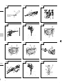 2
2
-
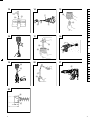 3
3
-
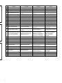 4
4
-
 5
5
-
 6
6
-
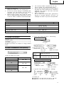 7
7
-
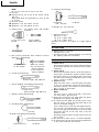 8
8
-
 9
9
-
 10
10
-
 11
11
-
 12
12
-
 13
13
-
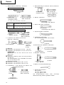 14
14
-
 15
15
-
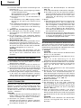 16
16
-
 17
17
-
 18
18
-
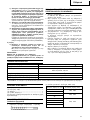 19
19
-
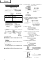 20
20
-
 21
21
-
 22
22
-
 23
23
-
 24
24
-
 25
25
-
 26
26
-
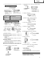 27
27
-
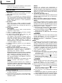 28
28
-
 29
29
-
 30
30
-
 31
31
-
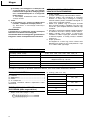 32
32
-
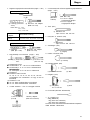 33
33
-
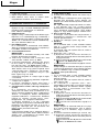 34
34
-
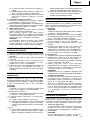 35
35
-
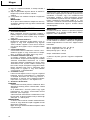 36
36
-
 37
37
-
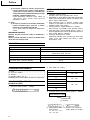 38
38
-
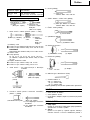 39
39
-
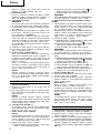 40
40
-
 41
41
-
 42
42
-
 43
43
-
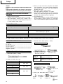 44
44
-
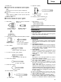 45
45
-
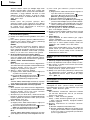 46
46
-
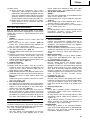 47
47
-
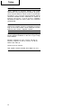 48
48
-
 49
49
-
 50
50
-
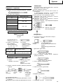 51
51
-
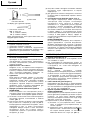 52
52
-
 53
53
-
 54
54
-
 55
55
-
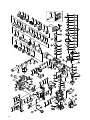 56
56
-
 57
57
-
 58
58
-
 59
59
-
 60
60
-
 61
61
-
 62
62


Hitachi DH 40MRY Handling Instructions Manual
- Kategori
- Döner çekiçler
- Tip
- Handling Instructions Manual
- Bu kılavuz aynı zamanda aşağıdakiler için de uygundur:
diğer dillerde
- slovenčina: Hitachi DH 40MRY
- polski: Hitachi DH 40MRY
İlgili makaleler
-
Hikoki DH50MB - 2" SDS Max Rotary Hammer Kullanım kılavuzu
-
-
Hitachi DH 30PC2 Kullanım kılavuzu
-
-
-
-
Hikoki DH24PM Kullanım kılavuzu
-
-
-