Yamaha R-S500 El kitabı
- Kategori
- Alıcı
- Tip
- El kitabı
Bu kılavuz aynı zamanda aşağıdakiler için de uygundur:

©
2010 Yamaha Corporation
Receiver
Ampli-Tuner
OWNER’S MANUAL
MODE D’EMPLOI
BEDIENUNGSANLEITUNG
BRUKSANVISNING
MANUALE DI ISTRUZIONI
MANUAL DE INSTRUCCIONES
GEBRUIKSAANWIJZING
ИНСТРУКЦИЯ ПО ЭКСПЛУАТАЦИИ
G
Printed in Malaysia WV17390-2

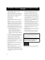
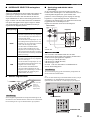
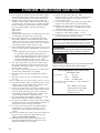
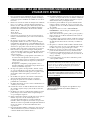
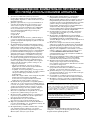
CAUTION: READ THIS BEFORE OPERATING YOUR UNIT.
i En
1 To assure the finest performance, please read this manual
carefully. Keep it in a safe place for future reference.
2 Install this sound system in a well ventilated, cool, dry,
clean place - away from direct sunlight, heat sources,
vibration, dust, moisture, and/or cold. For proper
ventilation, allow the following minimum clearances
around this unit.
Top: 30 cm (11-3/4 in)
Rear: 20 cm (7-7/8 in)
Sides: 20 cm (7-7/8 in)
3 Locate this unit away from other electrical appliances,
motors, or transformers to avoid humming sounds.
4 Do not expose this unit to sudden temperature changes
from cold to hot, and do not locate this unit in an
environment with high humidity (i.e. a room with a
humidifier) to prevent condensation inside this unit,
which may cause an electrical shock, fire, damage to this
unit, and/or personal injury.
5 Avoid installing this unit where foreign object may fall
onto this unit and/or this unit may be exposed to liquid
dripping or splashing. On the top of this unit, do not
place:
– Other components, as they may cause damage and/or
discoloration on the surface of this unit.
– Burning objects (i.e. candles), as they may cause fire,
damage to this unit, and/or personal injury.
– Containers with liquid in them, as they may fall and
liquid may cause electrical shock to the user and/or
damage to this unit.
6 Do not cover this unit with a newspaper, tablecloth,
curtain, etc. in order not to obstruct heat radiation. If the
temperature inside this unit rises, it may cause fire,
damage to this unit, and/or personal injury.
7 Do not plug in this unit to a wall outlet until all
connections are complete.
8 Do not operate this unit upside-down. It may overheat,
possibly causing damage.
9 Do not use force on switches, knobs and/or cords.
10 When disconnecting the power cable from the wall outlet,
grasp the plug; do not pull the cable.
11 Do not clean this unit with chemical solvents; this might
damage the finish. Use a clean, dry cloth.
12 Only voltage specified on this unit must be used. Using
this unit with a higher voltage than specified is dangerous
and may cause fire, damage to this unit, and/or personal
injury. Yamaha will not be held responsible for any
damage resulting from use of this unit with a voltage
other than specified.
13 To prevent damage by lightning, keep the power cable
and outdoor antennas disconnected from a wall outlet or
this unit during a lightning storm.
14 Do not attempt to modify or fix this unit. Contact
qualified Yamaha service personnel when any service is
needed. The cabinet should never be opened for any
reasons.
15 When not planning to use this unit for long periods of
time (i.e. vacation), disconnect the AC power plug from
the wall outlet.
16 Be sure to read the “TROUBLESHOOTING” section on
common operating errors before concluding that this unit
is faulty.
17 Before moving this unit, press A to turn off this unit, and
then disconnect the AC power plug from the wall outlet.
18 Condensation will form when the surrounding
temperature changes suddenly. Disconnect the power
cable from the outlet, then leave this unit alone.
19 When using this unit for a long time, this unit may
become warm. Turn the power off, then leave this unit
alone for cooling.
20 Install this unit near the AC outlet and where the AC
power plug can be reached easily.
21 The batteries shall not be exposed to excessive heat such
as sunshine, fire or the like.
22 Excessive sound pressure from earphones and
headphones can cause hearing loss.
This label is required to be attached to a product of which
the temperature of the top cover may be hot during
operation.
CAUTION: READ THIS BEFORE OPERATING YOUR UNIT.
As long as this unit is connected to the AC wall outlet, it is not
disconnected from the AC power source even if you turn off this
unit by A or set it to the standby mode by A button on the remote
control. In this state, this unit is designed to consume a very small
quantity of power.
WARNING
TO REDUCE THE RISK OF FIRE OR ELECTRIC SHOCK, DO
NOT EXPOSE THIS UNIT TO RAIN OR MOISTURE.

1 En
PREPARATIONINTRODUCTION
BASIC
OPERATION
ADDITIONAL
INFORMATION
ADVANCED
OPERATION
English
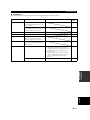
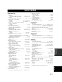
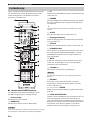
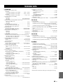
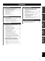
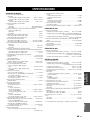
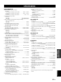
USEFUL FEATURES ............................................ 2
SUPPLIED ACCESSORIES ................................. 3
CONTROLS AND FUNCTIONS ......................... 4
Front panel................................................................. 4
Front panel display .................................................... 6
Rear panel.................................................................. 7
Remote control........................................................... 8
Using the remote control ........................................... 9
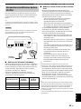
CONNECTIONS .................................................. 10
Connecting speakers and source components.......... 10
Connecting the FM and AM antennas..................... 12
Using COUPLER jacks (R-S700 only) ................... 13
Connecting power cable .......................................... 13
PLAYING AND RECORDING .......................... 14
Playing a source....................................................... 14
Adjusting the tonal quality....................................... 15
Recording a source .................................................. 17
Using the sleep timer ............................................... 17
FM/AM TUNING ................................................. 18
Automatic tuning ..................................................... 18
Manual tuning.......................................................... 19
Automatic station preset (FM stations only) ........... 20
Manual station preset............................................... 21
Recalling a preset station......................................... 22
Clearing a preset station........................................... 23
Clearing all preset stations....................................... 23
Receiving Radio Data System information
(FM stations only) ............................................... 24
TP Search function (FM stations only)................... 26
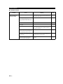
PLAYING BACK TUNES
FROM YOUR iPhone/iPod/
Bluetooth™ COMPONENT............................ 27
Using a Universal Dock for iPod............................. 28
Using a Wireless System for iPod ........................... 29
Using a Bluetooth Wireless Audio Receiver........... 30
SETTING THE OPTION MENU
FOR EACH INPUT SOURCE.........................32
Option menu items................................................... 32
ADVANCED SETUP ............................................34
Changing the ADVANCED SETUP
menu parameters.................................................. 34
Switching the remote control ID ............................. 35
REMOTE CONTROL FEATURES ...................36
Controlling this unit, a TV, or other components.... 36
Configuring the remote control ............................... 38
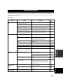
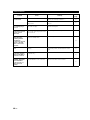
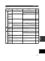
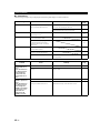
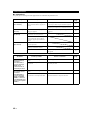
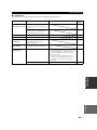
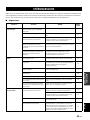
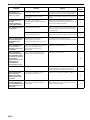
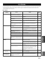
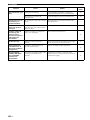
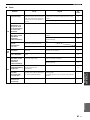
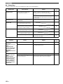
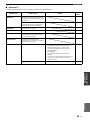
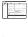
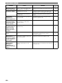
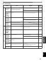
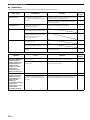
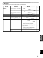
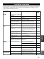
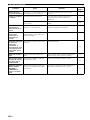
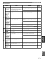
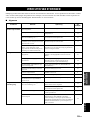
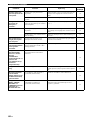
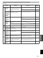
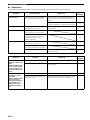
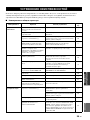
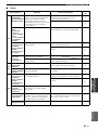
TROUBLESHOOTING .......................................39
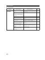
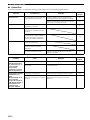
SPECIFICATIONS...............................................45
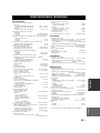
CONTENTS
INTRODUCTION
PREPARATION
BASIC OPERATION
ADVANCED OPERATION
ADDITIONAL INFORMATION

USEFUL FEATURES
2 En
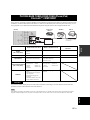
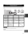
This unit allows you to:
*1
R-S700 only
*2
Optional Yamaha product required
iPhone, iPod
iPhone, iPod, iPod classic, iPod nano and iPod touch are trademarks of Apple Inc., registered in the U.S. and other
countries.
Bluetooth™
Bluetooth is a registered trademark of the Bluetooth SIG and is used by Yamaha in accordance with a license agreement.
• y indicates a tip for your operation.
• This manual is the owner’s manual for both the R-S700 and the R-S500. Model names are given where the details of functions are
unique to each model. Generally, illustrations of the R-S700 are used for explanations.
• Some operations can be performed by using either the buttons on the front panel of this unit or those on the remote controls. In case
the button names differ between this unit and the remote controls, the names of the buttons on the remote controls are given in
parentheses.
• This manual is printed prior to production. Design and specifications are subject to change in part as a result of improvements, etc. In
case of differences between the manual and the product, the product has priority.
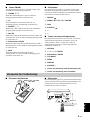
USEFUL FEATURES
Improve sound quality by using the CD Direct Amp
*1
and Pure
Direct functions
➡
p. 15
Play back music from your iPhone/iPod
*2
or Bluetooth
component
*2
➡
p. 27
Play back video content from your iPhone/iPod
*1 *2
➡
p. 28
Listen to FM and AM radio stations
➡
p. 18
Receive and display Radio Data System information
➡
p. 24
Boost bass sounds by connecting a subwoofer
➡
p. 10
Connect an external device
*1
such as a graphic equalizer or a
surround-sound processor
➡
p. 13
Use this unit’s remote control to operate other components such
as a CD player, BD/DVD player or TV
➡
p. 36
Save power by using the automatic power down function
➡
p. 34
INTRODUCTION

SUPPLIED ACCESSORIES
3 En
INTRODUCTION
English
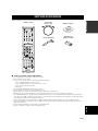
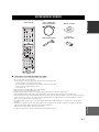
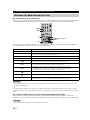
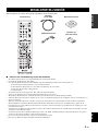
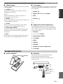
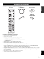
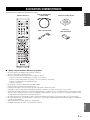
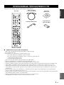
Please check that you received all of the following parts.
■ Notes on remote control and batteries
• Do not spill water or other liquids on the remote control.
• Do not drop the remote control.
• Do not leave or store the remote control in the following conditions:
– places of high humidity, such as near a bath
– places of high temperatures, such as near a heater or stove
– places of extremely low temperatures
– dusty places
• Use AAA, R03, UM-4 batteries for the remote control.
• Insert batteries according to the polarity markings (+ and -).
• Change all batteries if you notice the operation range of the remote control narrows.
• If the batteries run out, immediately remove them from the remote control to prevent an explosion or acid leak.
• If you find leaking batteries, discard the batteries immediately, taking care not to touch the leaked material. If the leaked material
comes into contact with your skin or gets into your eyes or mouth, rinse it away immediately and consult a doctor. Clean the battery
compartment thoroughly before installing new batteries.
• Do not use old batteries together with new ones. This may shorten the life of the new batteries or cause old batteries to leak.
• Do not use different types of batteries (such as alkaline and manganese batteries) together. Batteries that look the same may have a
different specification.
• Before inserting new batteries, wipe the battery compartment clean.
• Dispose of batteries according to your regional regulations.
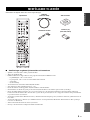
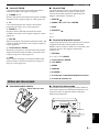
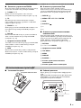
SUPPLIED ACCESSORIES
Remote control
Indoor FM antenna
AM loop antenna
Power cable
(R-S700 only)
Batteries (x2)
(AAA, R03, UM-4)

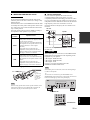
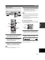
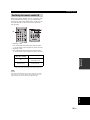
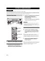
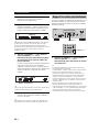
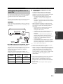
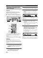
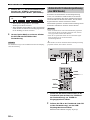
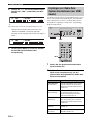
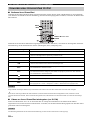
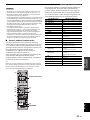
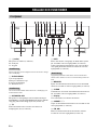
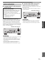
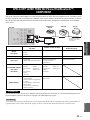
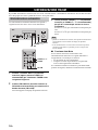
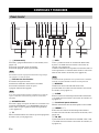
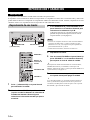
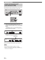
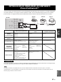
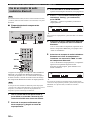
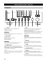
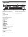
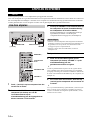
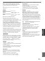
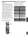
CONTROLS AND FUNCTIONS
4 En
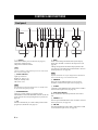
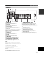
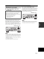
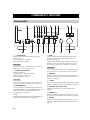
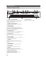
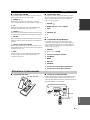
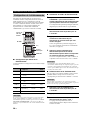
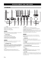
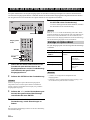
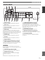
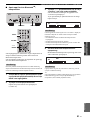
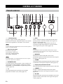
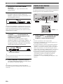
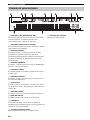
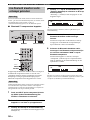
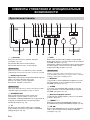
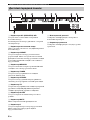
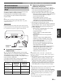
1 A (power)
Turns on and off the power of this unit (see page 14).
On position: Pushed inward
Off position: Released outward
This unit consumes a small amount of power even when turned
off or when in standby mode.
2 Power indicator
Lights up as follows:
Brightly lit: Power is on
Dimly lit: Standby mode
Off: Power is off
If an iPhone/iPod is charged while this unit is in standby mode,
the power indicator lights up brightly.
3 SPEAKERS A/B
Turns on or off the speaker set connected to the
SPEAKERS A and/or SPEAKERS B terminals on the rear
panel each time the corresponding button is pressed (see
page
14
).
4 TP
Searches automatically for a station that provides traffic
program (TP) broadcasts (see page 26).
5 INFO
Turns on and changes the Radio Data System display
mode when TUNER is selected as the input source (see
page 24).
Changes the playback information displayed about the
song playing on the iPhone/iPod when DOCK is selected
as the input source (see page 28).
Playback information can only be displayed for an iPhone/iPod
that is connected using a Universal Dock for iPod.
6 MEMORY
Stores the current FM/AM station as a preset when
TUNER is selected as the input source (see page 21).
7 CLEAR
Clears the current FM/AM preset station when TUNER is
selected as the input source (see page 23).
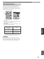
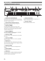
8 Front panel display
Shows information about the operational status of this
unit.
9 PRESET j / i
Selects a preset FM/AM station when TUNER is selected
as the input source (see page 22).
0 FM, AM
Sets the FM/AM tuner band to FM or AM when TUNER
is selected as the input source (see page 18).
CONTROLS AND FUNCTIONS
Front panel
(R-S700)
Note
Note
Note

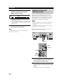
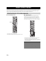
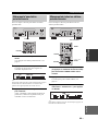
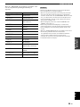
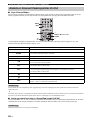
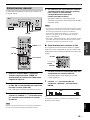
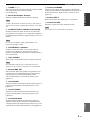
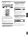
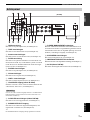
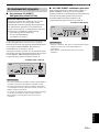
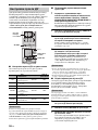
CONTROLS AND FUNCTIONS
5 En
INTRODUCTION
English
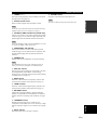
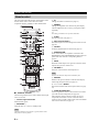
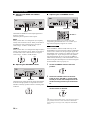
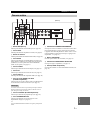
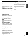
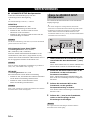
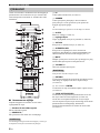
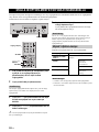
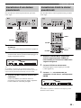
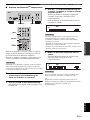
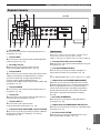
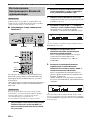
A TUNING jj / ii
Selects the tuning frequency when TUNER is selected as
the input source (see page 18).
B Remote control sensor
Receives infrared signals from the remote control.
Switch the remote control ID between ID1 and ID2 when using
multiple Yamaha receivers or amplifiers (see page 35).
C CD DIRECT AMP and indicator (R-S700 only)
Allows you to listen to a CD source in the purest possible
sound (see page 15). The indicator lights up and the front
panel display turns off when this function is turned on.
If both the CD DIRECT AMP and the PURE DIRECT are turned
on, only the CD DIRECT AMP will function.
D PURE DIRECT and indicator
Allows you to listen to a source in the purest possible
sound (see page 15). The indicator above it lights up and
the front panel display turns off when this function is
turned on.
E PHONES jack
Outputs audio to your headphones for private listening.
Press SPEAKER A/B so that the SP A/B indicators turn off
before you connect your headphones to the PHONES jack.
F REC OUT selector
Selects a source for recording to a CD recorder or to a tape
deck independently of the INPUT selector setting,
allowing you to record the selected source while listening
to another source (see page 17).
G BASS control
Increases or decreases the low frequency response. The
center position produces a flat response (see page 16).
H TREBLE control
Increases or decreases the high frequency response. The
center position produces a flat response (see page 16).
I BALANCE control
Adjusts the sound output balance of the left and right
speakers to compensate for sound imbalances caused by
speaker locations or listening room conditions (see page
16).
J LOUDNESS control
Retains a full tonal range at any volume level to
compensate for the human ears’ loss of sensitivity to high
and low-frequency ranges at a low volume level (see page
16).
K INPUT selector
Selects the input source you want to listen to.
L VOLUME control
Increases or decreases the sound output level.
This does not affect the output level of the REC jacks.
Note
Note
Note
Note

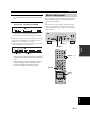
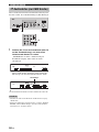
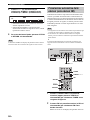
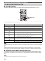
CONTROLS AND FUNCTIONS
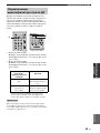
6 En
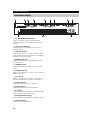
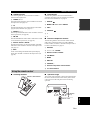
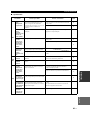
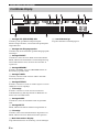
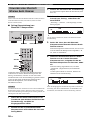
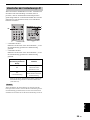
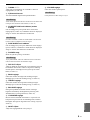
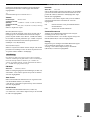
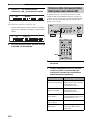
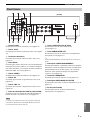
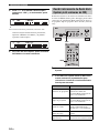
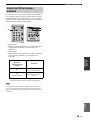
1 SP (SPEAKERS) A/B indicators
Light up according to the set of speakers selected.
Both indicators light up when both sets of speakers are
selected.
2 Input source indicators
Light up brightly to indicate the input source that is
currently selected.
3 PRESET indicator
Lights up when you recall a preset radio station. Blinks
while the automatic station preset feature is scanning for
FM stations to register as presets.
4 MEMORY indicator
Lights up or blinks when an FM/AM station is being
stored as a preset.
5 TUNED indicator
Lights up when this unit is tuned in to an FM or AM
station.
6 STEREO indicator
Lights up when this unit is receiving a strong signal for an
FM stereo broadcast.
7 TP indicator
Lights up when this unit is tuned in to a Traffic Program
(TP) station. Blinks when searching for a TP station.
8 SLEEP indicator
Lights up when the sleep timer is turned on.
9 MUTE indicator
Blinks while the MUTE function is turned on.
0 P indicator
Lights up when a preset number is selected. Blinks while
you are registering a preset radio station.
A Multi-information display
Shows information when adjusting or changing settings.
B Volume indicator
Displays the current volume level.
Front panel display

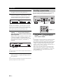
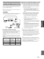
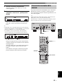
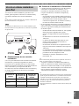
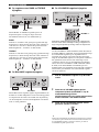
CONTROLS AND FUNCTIONS
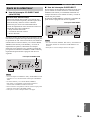
7 En
INTRODUCTION
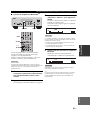
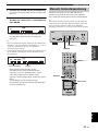
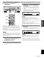
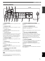
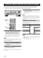
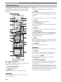
CONTROLS AND FUNCTIONS
English
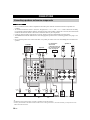
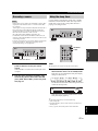
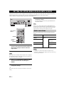
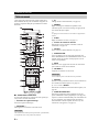
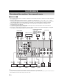
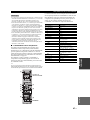
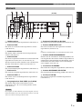
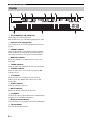
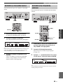
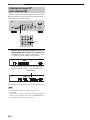
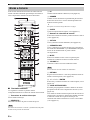
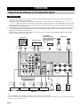
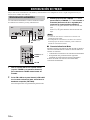
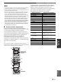
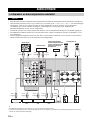
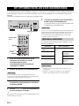
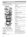
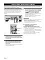
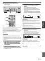
Rear panel
(R-S700)
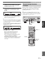
1 GND terminal
Used to connect a turntable (see page 10).
2 TAPE jacks
Used to connect a tape deck (see page 10).
3 Antenna terminals
Used to connect FM and AM antennas (see page 12).
4 DOCK jack
Used to connect an optional Yamaha Universal Dock for
iPod (such as the YDS-12), Wireless System for iPod
(YID-W10), or Bluetooth Wireless Audio Receiver
(YBA-10) (see page 27).
5 PHONO jacks
Used to connect a turntable (see page 10).
6 CD jacks
Used to connect a CD player (see page 10).
7 LINE 1-3 jacks
Used to connect audio components (see page 10).
8 iPod VIDEO output jack (R-S700 only)
Used to send iPhone/iPod video content to a video
monitor, such as a TV (see page 27).
Video content output is possible only when an iPhone/iPod is
connected this unit using a Universal Dock for iPod (such as the
YDS-12).
9 COUPLER jacks (R-S700 only)
Used to connect an external unit (see page 13).
0 SUBWOOFER OUT jack
Used to connect a subwoofer with built-in amplifier (see
page 10).
y
The SUBWOOFER OUT jack attenuates signals over 90 Hz.
A POWER MANAGEMENT switch
Used to enable or disable the automatic power down
function. When this function is enabled, this unit
automatically enters standby mode if it is not operated for
a certain amount of time (3 settings are available; see page
34).
B SPEAKERS terminals
Used to connect speakers (see page 10).
C IMPEDANCE SELECTOR switch
Used to select the impedance setting (see page 11).
D AC IN (R-S700 only)
Used to plug in the supplied power cable (see page 13).
Note

CONTROLS AND FUNCTIONS
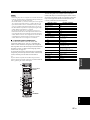
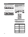
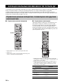
8 En
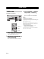
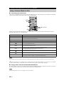
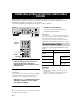
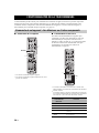
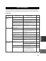
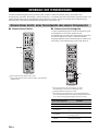
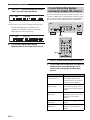
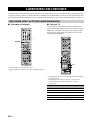
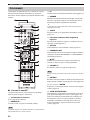
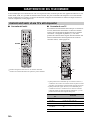
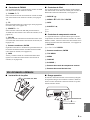
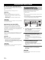
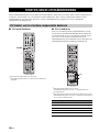
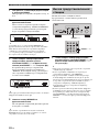
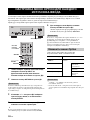
This section describes the function of each button on the
remote control used to control this unit or other
components made by Yamaha or other manufacturers.
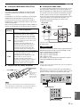
■ Common controls
The following buttons can be used no matter which input
source is selected.
1 Infrared signal transmitter
Sends infrared signals.
2 RECEIVER A
Turns this unit on, or sets it to standby mode.
This button functions only when the A (power) button on the
front panel is in the on position.
3 ID
Changes the remote control ID (see page 35).
4 DIMMER
Changes the brightness level of the front panel display.
Choose brightness from 3 levels by pressing this button
repeatedly.
y
This setting is retained even if you turn off this unit.
5 SLEEP
Sets the sleep timer (see page 17).
6 Input selector buttons
Selects the input source and changes the control area (see
page 36).
7 OPTION
Turns the OPTION menu on and off (see page 32).
8 SPEAKERS A/B
Turns on and off the set of speakers connected to the
SPEAKERS A and/or SPEAKERS B terminals on the rear
panel of this unit when the corresponding button is
pressed.
9 MUTE
Mutes the sound output. Press again to restore the sound
output to the previous volume level.
0 VOLUME +/–
Increases or decreases the sound output level.
This does not affect the output level of the REC jacks.
A RETURN
Returns to the previous menu or ends the menu display
when using the Option menu (see page 32).
B B / C / D / E / ENTER
Selects and confirms items in the Option menu (see page
32).
C CODE SET/RECEIVER
Used to program the remote control so that it can control
your other external components (see page 38).
After using the remote control to control one of your
components, this button is used to switch the remote
control to receiver mode so that remote control commands
will be sent to this unit (see page 37).
Remote control
Note
Note

CONTROLS AND FUNCTIONS
9 En
INTRODUCTION
English
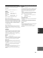
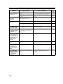
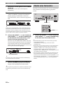
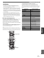
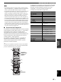
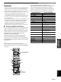
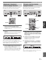
■ FM/AM controls
The following buttons can be used when TUNER is
selected as the input source.
D TUNING H / I
Selects the tuning frequency when TUNER is selected as
the input source (see page 18).
E TP
Searches automatically for a station that provides traffic
program (TP) broadcasts (see page 26).
F PRESET F / G
Selects a preset FM/AM station when TUNER is selected
as the input source (see page 22).
G FM, AM
Sets the FM/AM tuner band to FM or AM when TUNER
is selected as the input source (see page 18).
H Numeric buttons, ENTER
Specifies the frequency or the preset number of the FM/
AM station when TUNER is selected as the input source
(see page 19).
I INFO
Turns on and changes the Radio Data System display
mode when TUNER is selected as the input source (see
page 24).
■ iPod controls
The following buttons can be used when DOCK is
selected as the input source for listening to an iPhone/
iPod. For more information, see page 27.
A REPEAT
B MENU/ Ee / b / a / ENTER
I INFO
J SHUFFLE
K B
L C
■ External component controls
The following buttons can be used to control external
audio/video components when CD, TAPE, PHONO,
LINE1, LINE2, or LINE3 is selected as the input source.
For more information, see page 36.
A RETURN
B B / C / D / E / ENTER
H Numeric buttons, ENTER
J TOP MENU
K MENU
L DISPLAY
M SOURCE A
N External component control buttons
O TV control buttons
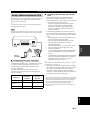
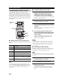
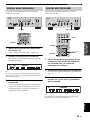
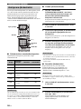
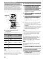
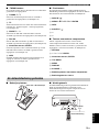
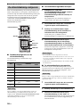
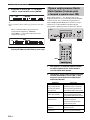
■ Installing batteries ■ Operation range
The remote control transmits a directional infrared beam.
Be sure to aim the remote control directly at the remote
control sensor on the front panel of this unit during
operation.
Using the remote control
AAA, R03, UM-4 batteries
Approximately
6 m (20 ft)
Remote control

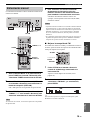
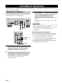
CONNECTIONS
10 En
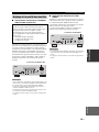
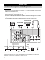
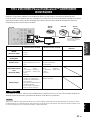
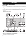
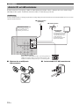
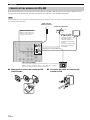
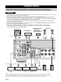
• Do not connect this unit or other components to the main power until all connections between components are
complete.
• All connections must be correct: L (left) to L, R (right) to R, “+” to “+” and “–” to “–”. If the connections are faulty,
no sound will be heard from the speakers, and if the polarity of the speaker connections is incorrect, the sound will be
unnatural and lack bass. Refer to the owner’s manual for each of your components.
• Use RCA cables for audio components (except for speaker connections and DOCK jack connections).
• The IMPEDANCE SELECTOR must be set to the appropriate position before connecting speakers. See page 11 for
details.
• Do not let bare speaker wires touch each other or any metal part of this unit. This could damage this unit and/or the
speakers.
y
• The PHONO jacks are designed for connecting a turntable with an MM cartridge.
• Connect your turntable to the GND terminal to reduce noise in the signal. However, for some turntables, you may hear less noise
without the GND connection.
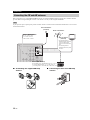
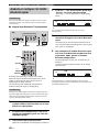
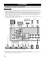
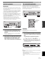
CONNECTIONS
Connecting speakers and source components
CAUTION
Turntable
VCR, etc.
Audio
out
CD recorder,
etc.
DVD player,
etc.
Tape deck
GND
Audio
out
Speakers A
Subwoofer
For information
about other
components that can
be connected to this
unit, see page 27.
Audio
in
Audio
out
Audio
out
Audio
out
Audio
in
Audio
out
Speakers B
CD player
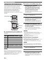
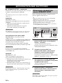
PREPARATION

11 En
CONNECTIONS
PREPARATION
English
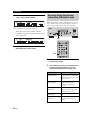
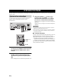
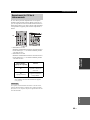
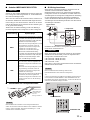
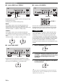
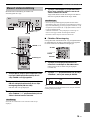
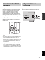
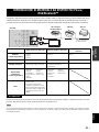
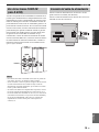
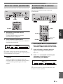
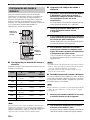
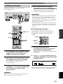
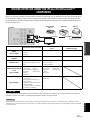
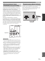
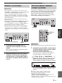
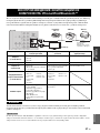
■ IMPEDANCE SELECTOR switch
Do not change the IMPEDANCE SELECTOR switch
while the power of this unit is turned on, as doing so may
damage the unit.
If the unit fails to turn on, the IMPEDANCE SELECTOR
switch may not be fully slid to either position. If this is the
case, remove the power cable and slide the switch all the
way to either position.
Select the switch position (LOW or HIGH) according to
the impedance of the speakers in your system.
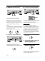
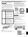
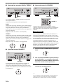
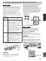
■ Connecting speaker cables
When inserting speaker cables into the speaker terminals, insert
only the bare speaker wire. If insulated cable is inserted, the
connection may be poor and sound may not be heard.
■ Bi-wire connection
Bi-wire connection separates the woofer from the
combined midrange and tweeter section. A bi-wire
compatible speaker has four binding post terminals. These
two sets of terminals allow the speaker to be split into two
independent sections. With these connections, the mid and
high frequency drivers are connected to one set of
terminals and the low frequency driver to another set of
terminals.
Connect the other speaker to the other set of terminals in
the same way.
When making bi-wire connections, set the IMPEDANCE
SELECTOR switch to HIGH or LOW depending on the
impedance of your speakers:
6 Ω or higher: HIGH (R-S700)
8 Ω or higher: HIGH (R-S500)
4 Ω or higher: LOW
See page 11 for more information about the
IMPEDANCE SELECTOR switch.
When making bi-wire connections, remove the shorting bridges
or cables on the speaker.
y
To use the bi-wire connections, press SPEAKERS A and
SPEAKERS B on the front panel or on the remote control so that
both SP A and B light up on the front panel display.
CAUTION
Switch
position
Impedance level
HIGH
• If you use one set (A or B), the impedance of
each speaker must be 6
Ω or higher (R-S700)
or 8
Ω or higher (R-S500).
• If you use two sets (A and B) simultaneously,
the impedance of each speaker must be 12
Ω
or higher (R-S700) or 16
Ω or higher
(R-S500).
• If you make bi-wire connections, the
impedance of each speaker must be 6
Ω or
higher (R-S700) or 8
Ω or higher (R-S500).
See page 11 for Bi-wire connection.
LOW
• If you use one set (A or B), the impedance of
each speaker must be 4
Ω or higher.
• If you use two sets (A and B) simultaneously,
the impedance of each speaker must be 8
Ω or
higher.
• If you make bi-wire connections, the
impedance of each speaker must be 4
Ω or
higher. See page 11 for Bi-wire connection.
Note
Remove
approximately
10 mm (3/8 in)
of insulation
from the end of
each speaker
cable.
CAUTION
Note
This unit
Speaker
SPEAKERS A/B
SPEAKERS A/B

12 En
CONNECTIONS
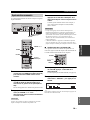
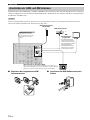
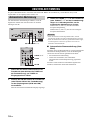
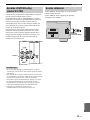
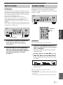
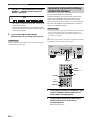
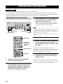
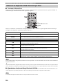
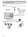
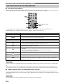
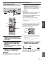
Indoor antennas for receiving FM and AM broadcasts are included with this unit. In general, these antennas should
provide sufficient signal strength. Connect each antenna correctly to the designated terminals.
If you experience poor reception quality, install an outdoor antenna. Consult the nearest authorized Yamaha dealer or service center
about outdoor antennas.
■ Assembling the supplied AM loop
antenna
■ Connecting the wire of the AM loop
antenna
Connecting the FM and AM antennas
Note
Indoor FM antenna
(included)
Outdoor AM antenna
Use 5 to 10 m of vinyl-
covered wire extended
outdoors from a window.
Outdoor FM antenna
Ground (GND terminal)
For maximum safety and minimum interference, connect
the antenna GND terminal to a good earth ground. A
good earth ground is a metal stake driven into moist earth.
• The AM loop antenna
should always be connected,
even if an outdoor AM
antenna is connected to this
unit.
• The AM loop antenna
should be placed away from
this unit.
AM loop antenna
(included)

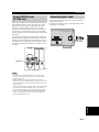
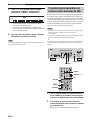
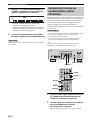
13 En
CONNECTIONS
PREPARATION
English
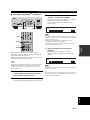
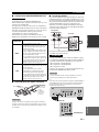
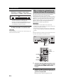
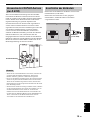
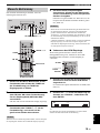
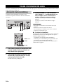
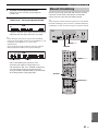
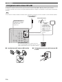
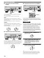
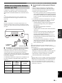
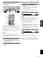
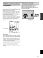
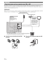
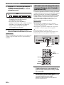
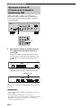
Removing the jumper pins from the PRE OUT/MAIN IN
jacks enables this unit to operate separately as a control
amplifier or a power amplifier. These jacks are used to
connect a signal-processing system such as a graphic
equalizer or a surround-sound processor to this unit. If an
external unit is connected to these jacks, the VOLUME
control of this unit can be used to adjust the overall sound
output level.
To connect an external unit, first remove the jumper pins
from the PRE OUT/MAIN IN jacks and then connect the
input jacks of that external unit to the PRE OUT jacks or
its output jacks to the MAIN IN jacks. For details, refer to
the owner’s manual included with the external unit to be
connected.
• If you do not use the COUPLER jacks, never remove the
jumper pins from these jacks. If removed, no sound will be
output from this unit.
• Before installing or removing the jumper pins, be sure to
disconnect the power cable of the unit. Leaving the power cable
connected could cause noise to be emitted from the speakers or
damage the unit.
• When you use this unit as a power amplifier, connect the output
jacks of the external control amplifier, etc. to the MAIN IN
jacks of this unit. In this case, the controls of this unit will not
function except the PHONES jack and the SPEAKERS A/B
buttons. Use the controls on the external control amplifier to
make volume adjustments, etc.
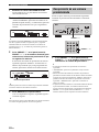
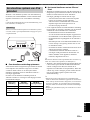
Plug the power cable into the AC IN on the rear panel of
this unit (R-S700 only).
Plug the power cable into the AC wall outlet after all other
connections are complete.
Using COUPLER jacks
(R-S700 only)
Notes
Jumper pins
Connecting power cable
Power cable
(R-S700 only)

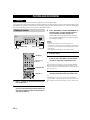
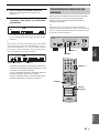
PLAYING AND RECORDING
14 En
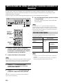
Extreme caution should be exercised when you play back CDs encoded in DTS.
If you play back a CD encoded in DTS on a CD player that does not support DTS, only noise will be heard, and this noise
may damage your speakers. Check whether your CD player supports CDs encoded in DTS. Also, check the sound output
level of your CD player before you play back a CD encoded in DTS.
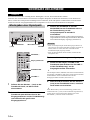
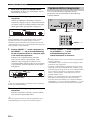
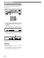
1 Press A (power) on the front panel inward to
turn on this unit.
2 Rotate the INPUT selector on the front panel
(or press one of the input selector buttons on
the remote control) to select the input source
you want to listen to.
3 Press SPEAKERS A and/or SPEAKERS B on
the front panel or on the remote control to
select speakers A and/or speakers B.
When speaker set A or speaker set B are turned on,
SP A or SP B is displayed on the front panel display
accordingly (see page 6).
• When one set of speakers is connected using bi-wire
connections, or when using two sets of speakers simultaneously
(A and B), make sure SP A and SP B are displayed on the front
panel display.
• When listening with headphones, turn off the speakers.
4 Play the source.
5 Rotate the VOLUME control on the front
panel (or press VOLUME +/– on the remote
control) to adjust the sound output level.
y
You can adjust the tonal quality by using the BASS, TREBLE,
BALANCE and LOUDNESS controls, the CD DIRECT AMP
switch (R-S700 only), or the PURE DIRECT switch on the front
panel (see page 15).
6 When finished listening, press A (power) on
the front panel outward to turn off this unit.
y
If RECEIVER A on the remote control is pressed while the
A (power) button on the front panel is in the on position, this unit
enters standby mode. Press RECEIVER A again to turn this unit
on.
PLAYING AND RECORDING
CAUTION
Playing a source
A (power)
SPEAKERS A/B INPUT selector
VOLUME
RECEIVER A
Input selector
buttons
SPEAKERS A/B
VOLUME +/–
Notes
BASIC OPERATION

15 En
PLAYING AND RECORDING
BASIC
OPERATION
English
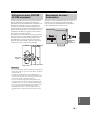
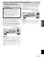
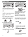
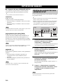
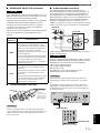
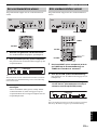
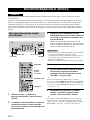
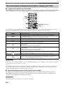
■ Using the CD DIRECT AMP switch
(R-S700 only)
Routes input signals from your CD player directly to the
specially built-in amplifier for the CD player. As a result,
the input signals bypass the INPUT selector and the
BASS, TREBLE, BALANCE and LOUDNESS controls
and then sent to the power amplifier, thus eliminating any
alterations to the CD signals and creating the purest
possible sound. The CD DIRECT AMP indicator lights up
and the front panel display turns off after a few seconds.
• If both the CD DIRECT AMP and the PURE DIRECT switches
are turned on, only the CD DIRECT AMP switch will function.
• The INPUT selector and the BASS, TREBLE, BALANCE, and
LOUDNESS controls do not function while the CD DIRECT
AMP feature is turned on.
• A CD player must be connected to the CD jacks in order to use
the CD DIRECT AMP feature.
• This setting is retained even if you turn off this unit.
■ Using the PURE DIRECT switch
Routes input signals from your audio sources so that the
input signals bypass the BASS, TREBLE, BALANCE and
LOUDNESS controls, thus eliminating any alterations to
the audio signals and creating the purest possible sound.
The PURE DIRECT indicator lights up and the front panel
display turns off after a few seconds.
• The BASS, TREBLE, BALANCE, and LOUDNESS controls
do not function while the PURE DIRECT feature is turned on.
• This setting is retained even if you turn off this unit.
Adjusting the tonal quality
CD Direct Amp feature
Generates a normal phase and reverse phase signal for
both the left and right channels from the input signal
and uses the four electronic volumes to send a
balanced signal to the amplifying circuit. This feature
provides clearer sound as a result of:
• improved signal-to-noise ratio
• external noise canceling
• reduced distortion
Notes
CD DIRECT AMP switch
Notes
PURE DIRECT switch

16 En
PLAYING AND RECORDING
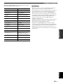
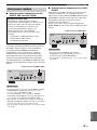
■ Adjusting the BASS and TREBLE
controls
The BASS and TREBLE controls adjust high and low
frequency response.
The center position produces a flat response.
BASS
When you feel there is not enough bass (low frequency
sound), rotate clockwise to boost. When you feel there is
too much bass, rotate counterclockwise to suppress.
Control range: –10 dB to +10 dB (20 Hz)
TREBLE
When you feel there is not enough treble (high frequency
sound), rotate clockwise to boost. When you feel there is
too much treble, rotate counterclockwise to suppress.
Control range: –10 dB to +10 dB (20 kHz)
■ Adjusting the BALANCE control
The BALANCE control adjusts the sound output balance
of the left and right speakers to compensate for sound
imbalance caused by speaker locations or listening room
conditions.
■ Adjusting the LOUDNESS control
Retain a full tonal range at any volume level, thus
compensating for the human ears’ loss of sensitivity to
high and low-frequency ranges at low volume.
If the CD DIRECT AMP switch (R-S700 only) or the
PURE DIRECT switch is turned on with the LOUDNESS
control set at a certain level, the input signals bypass the
LOUDNESS control, resulting in a sudden increase in the
sound output level. To prevent your ears or the speakers
from being damaged, be sure to press the CD DIRECT
AMP switch (R-S700 only) or the PURE DIRECT switch
after lowering the sound output level or after checking that
the LOUDNESS control is properly set.
1 Set the LOUDNESS control to the FLAT
position.
2 Rotate the VOLUME control on the front
panel (or press VOLUME +/– on the remote
control) to set the sound output level to the
loudest listening level that you would listen
to.
3 Rotate the LOUDNESS control until the
desired volume is obtained.
y
After setting the LOUDNESS control, enjoy listening to music at
your preferred volume level. If the effect of the LOUDNESS
control setting is too strong or weak, readjust the LOUDNESS
control.
BASS
TREBLE
BALANCE
CAUTION
LOUDNESS VOLUME
VOLUME +/–

17 En
PLAYING AND RECORDING
BASIC
OPERATION
English
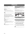
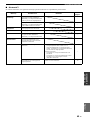
• Audio signals are not output to the TAPE REC or LINE 1 REC
output jacks when TAPE or LINE 1 is selected with the REC
OUT selector.
Audio signals are output to both the TAPE REC and the LINE 1
REC output jacks if when PHONO, DOCK, TUNER, CD,
SOURCE or LINE 2 is selected with the REC OUT selector.
• This unit must be turned on in order to record.
• The VOLUME, BASS, TREBLE, BALANCE and
LOUDNESS controls and the CD DIRECT AMP switch (R-
S700 only) and the PURE DIRECT switch have no effect on the
source being recorded.
• Check the copyright laws in your country before recording from
records, CDs, radio, etc. Recording copyright-protected
material may infringe on copyright laws.
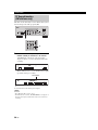
1 Rotate the REC OUT selector on the front
panel to select the source you want to
record.
When SOURCE is selected, the current input source
is output.
2 Play the source and begin recording using
the recording device connected to the REC
jacks (TAPE and/or LINE 1) on the rear panel.
See page 10.
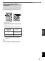
Use this feature to automatically set this unit to standby
mode after a certain amount of time. The sleep timer is
useful when you are going to sleep while this unit is
playing or recording a source.
The sleep timer can only be set with the remote control.
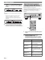
1 Press SLEEP repeatedly to set the amount of
time before this unit is set to standby mode.
Each time you press SLEEP, the front panel display
changes as shown below.
The SLEEP indicator blinks while setting the amount
of time for the sleep timer.
If the sleep timer is set, the SLEEP indicator on the
front panel display lights up.
y
To cancel the sleep timer, do one of the following:
• Select “Sleep Off”.
•Press RECEIVER A on the remote control to set this unit to
standby mode.
•Press A (power) on the front panel to turn off this unit.
Recording a source
Notes
INPUT selectorREC OUT selector
Using the sleep timer
Note
RECEIVER A
A (power)
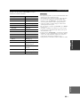
SLEEP

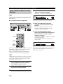
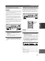
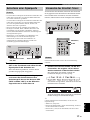
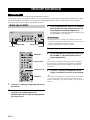
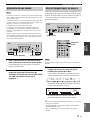
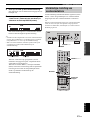
FM/AM TUNING
18 En
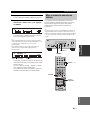
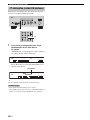
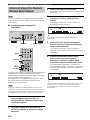
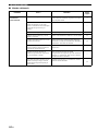
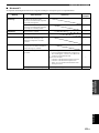
There are 2 tuning methods; automatic and manual. Select either method according to your preference and the strength of
station signals.
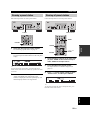
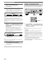
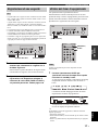
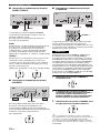
Automatic tuning is effective when station signals are
strong and there is no interference.
1 Rotate the INPUT selector on the front panel
(or press TUNER on the remote control) to
select TUNER as the input source.
2 Press FM or AM on the front panel (or FM or
AM on the remote control) to select the
reception band (FM or AM).
FM or AM is displayed on the front panel display.
3 Press and hold TUNING jj / ii on the front
panel (or TUNING H / I on the remote
control) for more than 1 second to begin
automatic tuning.
Press ii (or H) to tune in to a higher frequency.
Press jj (or I) to tune in to a lower frequency.
• When you tune in to a station, the frequency of the station is
displayed on the front panel display.
• If the tuning search does not stop at the desired station because
the station signals are weak, try using the manual tuning
method.
■ Auto Mute feature
When listening to an FM radio station, the output will
automatically be muted when the radio signal is weak if
the station was tuned in to by:
• using the automatic tuning feature
• recalling a preset that was registered using the
automatic preset registration feature
If you want to listen to a station that has a weak signal,
tune in to the station manually.
FM/AM TUNING
Automatic tuning
FM, AM
TUNING jj / ii
INPUT selector
TUNING H / I
FM, AM
TUNER
Notes
Sayfa yükleniyor...
Sayfa yükleniyor...
Sayfa yükleniyor...
Sayfa yükleniyor...
Sayfa yükleniyor...
Sayfa yükleniyor...
Sayfa yükleniyor...
Sayfa yükleniyor...
Sayfa yükleniyor...
Sayfa yükleniyor...
Sayfa yükleniyor...
Sayfa yükleniyor...
Sayfa yükleniyor...
Sayfa yükleniyor...
Sayfa yükleniyor...
Sayfa yükleniyor...
Sayfa yükleniyor...
Sayfa yükleniyor...
Sayfa yükleniyor...
Sayfa yükleniyor...
Sayfa yükleniyor...
Sayfa yükleniyor...
Sayfa yükleniyor...
Sayfa yükleniyor...
Sayfa yükleniyor...
Sayfa yükleniyor...
Sayfa yükleniyor...
Sayfa yükleniyor...
Sayfa yükleniyor...
Sayfa yükleniyor...
Sayfa yükleniyor...
Sayfa yükleniyor...
Sayfa yükleniyor...
Sayfa yükleniyor...
Sayfa yükleniyor...
Sayfa yükleniyor...
Sayfa yükleniyor...
Sayfa yükleniyor...
Sayfa yükleniyor...
Sayfa yükleniyor...
Sayfa yükleniyor...
Sayfa yükleniyor...
Sayfa yükleniyor...
Sayfa yükleniyor...
Sayfa yükleniyor...
Sayfa yükleniyor...
Sayfa yükleniyor...
Sayfa yükleniyor...
Sayfa yükleniyor...
Sayfa yükleniyor...
Sayfa yükleniyor...
Sayfa yükleniyor...
Sayfa yükleniyor...
Sayfa yükleniyor...
Sayfa yükleniyor...
Sayfa yükleniyor...
Sayfa yükleniyor...
Sayfa yükleniyor...
Sayfa yükleniyor...
Sayfa yükleniyor...
Sayfa yükleniyor...
Sayfa yükleniyor...
Sayfa yükleniyor...
Sayfa yükleniyor...
Sayfa yükleniyor...
Sayfa yükleniyor...
Sayfa yükleniyor...
Sayfa yükleniyor...
Sayfa yükleniyor...
Sayfa yükleniyor...
Sayfa yükleniyor...
Sayfa yükleniyor...
Sayfa yükleniyor...
Sayfa yükleniyor...
Sayfa yükleniyor...
Sayfa yükleniyor...
Sayfa yükleniyor...
Sayfa yükleniyor...
Sayfa yükleniyor...
Sayfa yükleniyor...
Sayfa yükleniyor...
Sayfa yükleniyor...
Sayfa yükleniyor...
Sayfa yükleniyor...
Sayfa yükleniyor...
Sayfa yükleniyor...
Sayfa yükleniyor...
Sayfa yükleniyor...
Sayfa yükleniyor...
Sayfa yükleniyor...
Sayfa yükleniyor...
Sayfa yükleniyor...
Sayfa yükleniyor...
Sayfa yükleniyor...
Sayfa yükleniyor...
Sayfa yükleniyor...
Sayfa yükleniyor...
Sayfa yükleniyor...
Sayfa yükleniyor...
Sayfa yükleniyor...
Sayfa yükleniyor...
Sayfa yükleniyor...
Sayfa yükleniyor...
Sayfa yükleniyor...
Sayfa yükleniyor...
Sayfa yükleniyor...
Sayfa yükleniyor...
Sayfa yükleniyor...
Sayfa yükleniyor...
Sayfa yükleniyor...
Sayfa yükleniyor...
Sayfa yükleniyor...
Sayfa yükleniyor...
Sayfa yükleniyor...
Sayfa yükleniyor...
Sayfa yükleniyor...
Sayfa yükleniyor...
Sayfa yükleniyor...
Sayfa yükleniyor...
Sayfa yükleniyor...
Sayfa yükleniyor...
Sayfa yükleniyor...
Sayfa yükleniyor...
Sayfa yükleniyor...
Sayfa yükleniyor...
Sayfa yükleniyor...
Sayfa yükleniyor...
Sayfa yükleniyor...
Sayfa yükleniyor...
Sayfa yükleniyor...
Sayfa yükleniyor...
Sayfa yükleniyor...
Sayfa yükleniyor...
Sayfa yükleniyor...
Sayfa yükleniyor...
Sayfa yükleniyor...
Sayfa yükleniyor...
Sayfa yükleniyor...
Sayfa yükleniyor...
Sayfa yükleniyor...
Sayfa yükleniyor...
Sayfa yükleniyor...
Sayfa yükleniyor...
Sayfa yükleniyor...
Sayfa yükleniyor...
Sayfa yükleniyor...
Sayfa yükleniyor...
Sayfa yükleniyor...
Sayfa yükleniyor...
Sayfa yükleniyor...
Sayfa yükleniyor...
Sayfa yükleniyor...
Sayfa yükleniyor...
Sayfa yükleniyor...
Sayfa yükleniyor...
Sayfa yükleniyor...
Sayfa yükleniyor...
Sayfa yükleniyor...
Sayfa yükleniyor...
Sayfa yükleniyor...
Sayfa yükleniyor...
Sayfa yükleniyor...
Sayfa yükleniyor...
Sayfa yükleniyor...
Sayfa yükleniyor...
Sayfa yükleniyor...
Sayfa yükleniyor...
Sayfa yükleniyor...
Sayfa yükleniyor...
Sayfa yükleniyor...
Sayfa yükleniyor...
Sayfa yükleniyor...
Sayfa yükleniyor...
Sayfa yükleniyor...
Sayfa yükleniyor...
Sayfa yükleniyor...
Sayfa yükleniyor...
Sayfa yükleniyor...
Sayfa yükleniyor...
Sayfa yükleniyor...
Sayfa yükleniyor...
Sayfa yükleniyor...
Sayfa yükleniyor...
Sayfa yükleniyor...
Sayfa yükleniyor...
Sayfa yükleniyor...
Sayfa yükleniyor...
Sayfa yükleniyor...
Sayfa yükleniyor...
Sayfa yükleniyor...
Sayfa yükleniyor...
Sayfa yükleniyor...
Sayfa yükleniyor...
Sayfa yükleniyor...
Sayfa yükleniyor...
Sayfa yükleniyor...
Sayfa yükleniyor...
Sayfa yükleniyor...
Sayfa yükleniyor...
Sayfa yükleniyor...
Sayfa yükleniyor...
Sayfa yükleniyor...
Sayfa yükleniyor...
Sayfa yükleniyor...
Sayfa yükleniyor...
Sayfa yükleniyor...
Sayfa yükleniyor...
Sayfa yükleniyor...
Sayfa yükleniyor...
Sayfa yükleniyor...
Sayfa yükleniyor...
Sayfa yükleniyor...
Sayfa yükleniyor...
Sayfa yükleniyor...
Sayfa yükleniyor...
Sayfa yükleniyor...
Sayfa yükleniyor...
Sayfa yükleniyor...
Sayfa yükleniyor...
Sayfa yükleniyor...
Sayfa yükleniyor...
Sayfa yükleniyor...
Sayfa yükleniyor...
Sayfa yükleniyor...
Sayfa yükleniyor...
Sayfa yükleniyor...
Sayfa yükleniyor...
Sayfa yükleniyor...
Sayfa yükleniyor...
Sayfa yükleniyor...
Sayfa yükleniyor...
Sayfa yükleniyor...
Sayfa yükleniyor...
Sayfa yükleniyor...
Sayfa yükleniyor...
Sayfa yükleniyor...
Sayfa yükleniyor...
Sayfa yükleniyor...
Sayfa yükleniyor...
Sayfa yükleniyor...
Sayfa yükleniyor...
Sayfa yükleniyor...
Sayfa yükleniyor...
Sayfa yükleniyor...
Sayfa yükleniyor...
Sayfa yükleniyor...
Sayfa yükleniyor...
Sayfa yükleniyor...
Sayfa yükleniyor...
Sayfa yükleniyor...
Sayfa yükleniyor...
Sayfa yükleniyor...
Sayfa yükleniyor...
Sayfa yükleniyor...
Sayfa yükleniyor...
Sayfa yükleniyor...
Sayfa yükleniyor...
Sayfa yükleniyor...
Sayfa yükleniyor...
Sayfa yükleniyor...
Sayfa yükleniyor...
Sayfa yükleniyor...
Sayfa yükleniyor...
Sayfa yükleniyor...
Sayfa yükleniyor...
Sayfa yükleniyor...
Sayfa yükleniyor...
Sayfa yükleniyor...
Sayfa yükleniyor...
Sayfa yükleniyor...
Sayfa yükleniyor...
Sayfa yükleniyor...
Sayfa yükleniyor...
Sayfa yükleniyor...
Sayfa yükleniyor...
Sayfa yükleniyor...
Sayfa yükleniyor...
Sayfa yükleniyor...
Sayfa yükleniyor...
Sayfa yükleniyor...
Sayfa yükleniyor...
Sayfa yükleniyor...
Sayfa yükleniyor...
Sayfa yükleniyor...
Sayfa yükleniyor...
Sayfa yükleniyor...
Sayfa yükleniyor...
Sayfa yükleniyor...
Sayfa yükleniyor...
Sayfa yükleniyor...
Sayfa yükleniyor...
Sayfa yükleniyor...
Sayfa yükleniyor...
Sayfa yükleniyor...
Sayfa yükleniyor...
Sayfa yükleniyor...
Sayfa yükleniyor...
Sayfa yükleniyor...
Sayfa yükleniyor...
Sayfa yükleniyor...
Sayfa yükleniyor...
Sayfa yükleniyor...
Sayfa yükleniyor...
Sayfa yükleniyor...
Sayfa yükleniyor...
Sayfa yükleniyor...
Sayfa yükleniyor...
Sayfa yükleniyor...
Sayfa yükleniyor...
Sayfa yükleniyor...
Sayfa yükleniyor...
Sayfa yükleniyor...
Sayfa yükleniyor...
Sayfa yükleniyor...
Sayfa yükleniyor...
Sayfa yükleniyor...
Sayfa yükleniyor...
Sayfa yükleniyor...
Sayfa yükleniyor...
Sayfa yükleniyor...
Sayfa yükleniyor...
Sayfa yükleniyor...
Sayfa yükleniyor...
Sayfa yükleniyor...
Sayfa yükleniyor...
Sayfa yükleniyor...
Sayfa yükleniyor...
Sayfa yükleniyor...
Sayfa yükleniyor...
Sayfa yükleniyor...
Sayfa yükleniyor...
Sayfa yükleniyor...
Sayfa yükleniyor...
Sayfa yükleniyor...
Sayfa yükleniyor...
Sayfa yükleniyor...
Sayfa yükleniyor...
Sayfa yükleniyor...
Sayfa yükleniyor...
Sayfa yükleniyor...
Sayfa yükleniyor...
Sayfa yükleniyor...
Sayfa yükleniyor...
Sayfa yükleniyor...
Sayfa yükleniyor...
Sayfa yükleniyor...
Sayfa yükleniyor...
Sayfa yükleniyor...
Sayfa yükleniyor...
Sayfa yükleniyor...
Sayfa yükleniyor...
Sayfa yükleniyor...
Sayfa yükleniyor...
Sayfa yükleniyor...
Sayfa yükleniyor...
Sayfa yükleniyor...
Sayfa yükleniyor...
Sayfa yükleniyor...
Sayfa yükleniyor...
Sayfa yükleniyor...
Sayfa yükleniyor...
Sayfa yükleniyor...
Sayfa yükleniyor...
-
 1
1
-
 2
2
-
 3
3
-
 4
4
-
 5
5
-
 6
6
-
 7
7
-
 8
8
-
 9
9
-
 10
10
-
 11
11
-
 12
12
-
 13
13
-
 14
14
-
 15
15
-
 16
16
-
 17
17
-
 18
18
-
 19
19
-
 20
20
-
 21
21
-
 22
22
-
 23
23
-
 24
24
-
 25
25
-
 26
26
-
 27
27
-
 28
28
-
 29
29
-
 30
30
-
 31
31
-
 32
32
-
 33
33
-
 34
34
-
 35
35
-
 36
36
-
 37
37
-
 38
38
-
 39
39
-
 40
40
-
 41
41
-
 42
42
-
 43
43
-
 44
44
-
 45
45
-
 46
46
-
 47
47
-
 48
48
-
 49
49
-
 50
50
-
 51
51
-
 52
52
-
 53
53
-
 54
54
-
 55
55
-
 56
56
-
 57
57
-
 58
58
-
 59
59
-
 60
60
-
 61
61
-
 62
62
-
 63
63
-
 64
64
-
 65
65
-
 66
66
-
 67
67
-
 68
68
-
 69
69
-
 70
70
-
 71
71
-
 72
72
-
 73
73
-
 74
74
-
 75
75
-
 76
76
-
 77
77
-
 78
78
-
 79
79
-
 80
80
-
 81
81
-
 82
82
-
 83
83
-
 84
84
-
 85
85
-
 86
86
-
 87
87
-
 88
88
-
 89
89
-
 90
90
-
 91
91
-
 92
92
-
 93
93
-
 94
94
-
 95
95
-
 96
96
-
 97
97
-
 98
98
-
 99
99
-
 100
100
-
 101
101
-
 102
102
-
 103
103
-
 104
104
-
 105
105
-
 106
106
-
 107
107
-
 108
108
-
 109
109
-
 110
110
-
 111
111
-
 112
112
-
 113
113
-
 114
114
-
 115
115
-
 116
116
-
 117
117
-
 118
118
-
 119
119
-
 120
120
-
 121
121
-
 122
122
-
 123
123
-
 124
124
-
 125
125
-
 126
126
-
 127
127
-
 128
128
-
 129
129
-
 130
130
-
 131
131
-
 132
132
-
 133
133
-
 134
134
-
 135
135
-
 136
136
-
 137
137
-
 138
138
-
 139
139
-
 140
140
-
 141
141
-
 142
142
-
 143
143
-
 144
144
-
 145
145
-
 146
146
-
 147
147
-
 148
148
-
 149
149
-
 150
150
-
 151
151
-
 152
152
-
 153
153
-
 154
154
-
 155
155
-
 156
156
-
 157
157
-
 158
158
-
 159
159
-
 160
160
-
 161
161
-
 162
162
-
 163
163
-
 164
164
-
 165
165
-
 166
166
-
 167
167
-
 168
168
-
 169
169
-
 170
170
-
 171
171
-
 172
172
-
 173
173
-
 174
174
-
 175
175
-
 176
176
-
 177
177
-
 178
178
-
 179
179
-
 180
180
-
 181
181
-
 182
182
-
 183
183
-
 184
184
-
 185
185
-
 186
186
-
 187
187
-
 188
188
-
 189
189
-
 190
190
-
 191
191
-
 192
192
-
 193
193
-
 194
194
-
 195
195
-
 196
196
-
 197
197
-
 198
198
-
 199
199
-
 200
200
-
 201
201
-
 202
202
-
 203
203
-
 204
204
-
 205
205
-
 206
206
-
 207
207
-
 208
208
-
 209
209
-
 210
210
-
 211
211
-
 212
212
-
 213
213
-
 214
214
-
 215
215
-
 216
216
-
 217
217
-
 218
218
-
 219
219
-
 220
220
-
 221
221
-
 222
222
-
 223
223
-
 224
224
-
 225
225
-
 226
226
-
 227
227
-
 228
228
-
 229
229
-
 230
230
-
 231
231
-
 232
232
-
 233
233
-
 234
234
-
 235
235
-
 236
236
-
 237
237
-
 238
238
-
 239
239
-
 240
240
-
 241
241
-
 242
242
-
 243
243
-
 244
244
-
 245
245
-
 246
246
-
 247
247
-
 248
248
-
 249
249
-
 250
250
-
 251
251
-
 252
252
-
 253
253
-
 254
254
-
 255
255
-
 256
256
-
 257
257
-
 258
258
-
 259
259
-
 260
260
-
 261
261
-
 262
262
-
 263
263
-
 264
264
-
 265
265
-
 266
266
-
 267
267
-
 268
268
-
 269
269
-
 270
270
-
 271
271
-
 272
272
-
 273
273
-
 274
274
-
 275
275
-
 276
276
-
 277
277
-
 278
278
-
 279
279
-
 280
280
-
 281
281
-
 282
282
-
 283
283
-
 284
284
-
 285
285
-
 286
286
-
 287
287
-
 288
288
-
 289
289
-
 290
290
-
 291
291
-
 292
292
-
 293
293
-
 294
294
-
 295
295
-
 296
296
-
 297
297
-
 298
298
-
 299
299
-
 300
300
-
 301
301
-
 302
302
-
 303
303
-
 304
304
-
 305
305
-
 306
306
-
 307
307
-
 308
308
-
 309
309
-
 310
310
-
 311
311
-
 312
312
-
 313
313
-
 314
314
-
 315
315
-
 316
316
-
 317
317
-
 318
318
-
 319
319
-
 320
320
-
 321
321
-
 322
322
-
 323
323
-
 324
324
-
 325
325
-
 326
326
-
 327
327
-
 328
328
-
 329
329
-
 330
330
-
 331
331
-
 332
332
-
 333
333
-
 334
334
-
 335
335
-
 336
336
-
 337
337
-
 338
338
-
 339
339
-
 340
340
-
 341
341
-
 342
342
-
 343
343
-
 344
344
-
 345
345
-
 346
346
-
 347
347
-
 348
348
-
 349
349
-
 350
350
-
 351
351
-
 352
352
-
 353
353
-
 354
354
-
 355
355
-
 356
356
-
 357
357
-
 358
358
-
 359
359
-
 360
360
-
 361
361
-
 362
362
-
 363
363
-
 364
364
-
 365
365
-
 366
366
-
 367
367
-
 368
368
-
 369
369
-
 370
370
-
 371
371
-
 372
372
-
 373
373
-
 374
374
-
 375
375
-
 376
376
-
 377
377
-
 378
378
-
 379
379
-
 380
380
-
 381
381
-
 382
382
-
 383
383


Yamaha R-S500 El kitabı
- Kategori
- Alıcı
- Tip
- El kitabı
- Bu kılavuz aynı zamanda aşağıdakiler için de uygundur:
diğer dillerde
- español: Yamaha R-S500 El manual del propietario
- français: Yamaha R-S500 Le manuel du propriétaire
- italiano: Yamaha R-S500 Manuale del proprietario
- svenska: Yamaha R-S500 Bruksanvisning
- čeština: Yamaha R-S500 Návod k obsluze
- Deutsch: Yamaha R-S500 Bedienungsanleitung
- English: Yamaha R-S500 Owner's manual
- dansk: Yamaha R-S500 Brugervejledning
- русский: Yamaha R-S500 Инструкция по применению
- suomi: Yamaha R-S500 Omistajan opas
- Nederlands: Yamaha R-S500 de handleiding
- română: Yamaha R-S500 Manualul proprietarului
