
Ceiling Mount Bracket
PMT-L21 (for Low Ceilings)
PMT-H25 (for High Ceilings)
Installation Manual
Be sure to read this manual thoroughly
before using this bracket. After you have
read this manual, retain it for future
reference.
When installing the projector using this
bracket, all installation work must be
performed by a qualified contractor or
dealer personnel. The customer must
never attempt to perform this installation
work.
SAFETY INSTRUCTIONS .............................................................................................................2
PACKING LIST .............................................................................................................................. 4
NAMES OF PARTS ....................................................................................................................... 5
DIMENSIONS OF PARTS .............................................................................................................7
SCREEN SIZE AND SETTING-UP DISTANCE ............................................................................ 8
INSTALLATION EXAMPLES....................................................................................................... 10
INSTALLING THE PROJECTOR ................................................................................................. 11
ADJUSTING THE PROJECTION ANGLE................................................................................... 14
SPECIFICATIONS ....................................................................................................................... 16
Contents
English
Français
Deutsch
Svenska
Italiano
Español
Nederlands
(PMT-L21)
(PMT-H25)

PMT-L21/PMT-H25
SAFETY INSTRUCTIONS
1. Always follow the instructions set forth in this manual when installing the projector
using this bracket.
Improper or inadequate installation could cause the projector to fall and injure someone.
2. The installation must be secure enough to bear the weight of the projector, the ceiling
bracket, and other hardware indefinitely, and must also be secure enough to withstand
vibration.
Inadequate installation could cause the projector to fall and injure someone.
3. To ensure safety, all bolts and screws must be tightened securely.
Loose bolts or screws could cause the projector to fall and injure someone.
4. Use only the parts provided with the bracket, and any other parts (commrecially
available) that are specified in this manual.
Using other parts could cause the projector to fall and injure someone.
5. Do not modify the bracket or the parts provided with the bracket.
Modifying the bracket or the other parts could cause the projector to fall and injure someone.
6. Do not use damaged parts.
Using damaged parts could cause the projector to fall and injure someone.
If any parts become damaged, contact your dealer.
7. Make sure to leave enough open space around the unit to allow heat generated by the
projector to dissipate.
Failure to provide adequate space around the unit could cause the projector to overheat internally, causing a
fire.
8. Before replacing the lamp cartridge, always remove the projector (with the mounting
adapter attached) from the ceiling bracket.
Attempting to replace the lamp cartridge while the projector is attached to the ceiling bracket could cause
the projector or the ceiling bracket to fall and injure someone.
E-2

E-3
English
Français
Deutsch
Svenska
Italiano
Español
Nederlands
9. Never hang from the projector or the ceiling bracket.
Hanging from the projector or the ceiling bracket could cause the projector or the ceiling bracket to fall and
injure someone.
10. Do not install the projector in a location near an air conditioning vent or in a location
subject to vibration.
Such conditions could have an adverse effect on the projector, and could even cause a fire or electric shock.
11. Do not install the projector in a location that is subject to high levels of dust or
humidity.
Dust accumulating inside the projector could cause a short circuit that in turn could cause a fire or electric
shock.
12. Do not install the projector in a location that is exposed to direct sunlight or in a
location that is subject to extreme fluctuations in temperature (such as near an air
conditioner).
Such conditions can cause the projector housing to warp or to become discolored.
13. Do not wipe the exterior of the ceiling bracket with benzene, paint thinner or cleaning
compounds.
Doing so could damage the finish.
14. Special techniques and experience are essential when installing the projector using
this bracket. Request that your dealer arrange to have the equipment installed. The
customer should never attempt to suspend the projector from the ceiling.
Improper installation could cause the ceiling bracket or the projector to fall and injure someone.
15. Once the projector is installed, safety checks should be conducted on a regular basis.
If the projector is used over an extended period of time, screws can become loose and the installation can
become weaker due to the passage of time, vibration, etc.

E-4
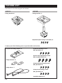
PACKING LIST
Check that all of the following parts are included.
PMT-L21
Ceiling bracket x 1
PMT-H25
Ceiling bracket x 1
Common parts (The following parts are provided with each bracket.)
Projector mounting adapter x 1
Projector mounting screws
(M4, pan head) x 4
Adjustment pole locking screws (M5) x 4
Safety brackets x 2
Safety wires x 2
Vertical angle adjustment screws
(M6, hexagonal head) x 4
Safety bracket mounting screws
(M4, pan head) x 4
Safety wire mounting screws
(M4, pan head) x 4
Installation Manual x 1

E-5
English
Français
Deutsch
Svenska
Italiano
Español
Nederlands
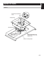
NAMES OF PARTS
PMT-L21
Ceiling bracket
Projector mounting adapter
Tilt angle adjustment screws
(There are also screws on the
opposite side.)
Horizontal angle adjustment
screws
Mounting guide pin
Vertical angle adjustment screws
(There are also screws on the
opposite side.)

E-6
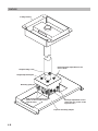
PMT-H25
Height locking screw
Ceiling bracket
Projector mounting adapter
Tilt angle adjustment screws
(There are also screws on the
opposite side.)
Horizontal angle adjustment screw
(four in total)
Height adjustment pole
Mounting guide pin
Vertical angle adjustment screws
(There are also screws on the
opposite side.)

E-7
English
Français
Deutsch
Svenska
Italiano
Español
Nederlands
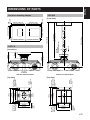
DIMENSIONS OF PARTS
Projector mounting adapter
with the LPX-500 installed
[Top View]
PMT-H25
[Front View]
with the LPX-500 installed
[Top View]
PMT-L21
[Front View]
Ø10 x 13 mm
(Ø3/8 x 1/2 inch)
(elliptical hole)
Ø10 mm
(Ø3/8 inch)
(hole)
Ø9 mm
(Ø3/8 inch)
(hole)
Ø9 x 13 mm
(Ø3/8 x 1/2 inch)
(elliptical hole)
10˚
10˚
196 mm
170 mm
140 mm
120 mm
156 mm
777 to 1347 mm
887 to 1457 mm
226 mm
200 mm
140 mm
175 mm
Ø8.8 mm
(Ø3/16 inch)
(fully penetrating holes)
(7-3/4 inch)
(6-11/16 inch)
(5-1/2 inch)
(4-3/4 inch)
(6-1/8 inch)
(30-9/16 to 53 inch)
(34-15/16 to 57-3/8 inch)
(1-3/16 inch)
Ø10 x 13 mm
(Ø3/8 x 1/2 inch)
(elliptical hole)
Ø10 mm
(Ø3/8 inch)
(hole)
Ø9 mm
(Ø3/8 inch)
(hole)
Ø9 x 13 mm
(Ø3/8 x 1/2 inch)
(elliptical hole)
(8-7/8 inch)
(7-7/8 inch)
30 mm
(5-1/2 inch)
(6-7/8 inch)
159 mm (6-1/4 inch)
8 mm
(5/16 inch)
8 mm
(5/16 inch)
178 mm (7-1/16 inch)
184 mm (7-1/4 inch) 178.5 mm (7 inch)
170.5 mm (6-3/4 inch)
170.5 mm (6-3/4 inch) 170.5 mm (6-3/4 inch)
147.3 mm (5-3/4 inch)
175 mm (6-7/8 inch)
192 mm
(7-9/16 inch)
81 mm
(3-3/16 inch)
137 mm
(5-3/8 inch)
10° 10°
832 to 1402 mm
(32-3/4 to 55-3/16 inch)

E-8
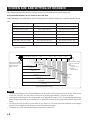
SCREEN SIZE AND SETTING-UP DISTANCE
The distance between the projector and the screen (16:9) determines the actual image size.
Recommended distance: 0.9 to 13.0 m (2.9 to 12.6 feet)
While referring to the table below, position the projector so that the image size is smaller than the screen
size.
Screen size (cm [feet])
Approximate projection size* (m [feet])
Distance in Fig. A below (cm [feet])
30" (66 x 37 [2.1 x 1.2]) 0.9 to 1.2 [2.9 to 3.9] 5.0 to 5.1 [0.16 to 0.17]
40" (89 x 50 [2.8 x 1.6]) 1.2 to 1.6 [3.9 to 5.2] 6.7 to 6.8 [0.22 to 0.22]
60" (130 x 75 [4.2 x 2.4]) 1.8 to 2.5 [5.9 to 8.2] 10.2 [0.33]
80" (180 x 100 [5.7 x 3.2]) 2.5 to 3.4 [8.2 to 11.1] 13.6 to 13.7 [0.45 to 0.45]
100" (220 x 120 [7.2 x 4.1]) 3.1 to 4.3 [10.1 to 14.1] 17.0 to 17.1 [0.56 to 0.56]
200" (440 x 250 [14.4 x 8.2]) 6.3 to 8.6 [20.6 to 28.2] 34.0 to 34.3 [1.12 to 1.13]
300" (660 x 370 [21.6 x 12.1]) 9.5 to 13.0 [31.1 to 42.6] 51.0 to 51.4 [1.67 to 1.69]
* Distance and dimensions should be used as a guide for installation. The actual distance will vary depending on
projection conditions.
Distance from center of
ceiling bracket to front
edge of projector:
Approx. 12 cm
Distance from ceiling
surface to center of
lens:
PMT-L21:
Approx. 19 cm
PMT-H25:
89 to 146 cm
30"
(66 × 37)
40"
(89 × 50)
60"
(130 × 75)
80"
(180 × 100)
100"
(220 × 120)
200"
(440 × 250)
Screen size (cm)
300"
(660 × 370)
Approximate projection size (m)
0.9 to 1.2
1.2 to 1.6
1.8 to 2.5
2.5 to 3.4
3.1 to 4.3
6.3 to 8.6
9.5 to 13.0
5.0 to
5.1
6.7 to
6.8
10.2 13.6 to
13.7
17.0 to
17.1
34.0 to
34.3
51.0 to
51.4
Distance from center of
lens to top edge of screen
(cm)
Notes
• The projection distance is the horizontal distance from the surface of the projector lens to the surface of the screen.
In the case of the LPX-500, the surface of the lens is recessed by approximately 3 cm from its exterior.
• Although the vertical angle of the ceiling bracket can be adjusted in a range of ±15°, a large angle adjustment may
distort the projected image. We recommend you to adjust both the angle of the ceiling bracket and the angle of the
screen.
• The lens of the LPX-500 allows a zoom ration of up to about 1.35. The image size at the maximum zoom setting is
about 1.35 times bigger than the image size at the minimum zoom setting.
• The image size will be reduced when keystone correction is carried out.

E-9
English
Français
Deutsch
Svenska
Italiano
Español
Nederlands
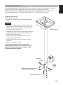
PMT-H25 height adjustment
The height adjustment pole for the PMT-H25 has holes spaced 3 cm apart that can be used to adjust the
height. When the bracket is shipped from the factory, the pole is set at the shortest height.
Follow the procedure described below to adjust the pole to the appropriate height. For details on the
appropriate height, refer to “SCREEN SIZE AND SETTING-UP DISTANCE” on page 8.
[Adjustment Procedure]
1
Remove the safety pin.
2 Loosen the nut, and then remove the height locking
screw.
Caution
• Removing the height locking screw will unlock the height
adjustment pole from the ceiling bracket. In order to ensure
that the height adjustment pole does not fall, always hold
the pole while performing this work.
3
Determine the correct position in accordance with the
height of the screen, insert the height locking screw,
and then hand-tighten the nut.
4 Securely tighten the four height adjustment pole
locking screws (M5) provided.
5 Securely tighten the nut that was previously hand-
tightened.
6 Be sure to insert the safety pin.
After adjusting the height, make sure that the
adjustment pole locking screws and the nut are all
tightened securely. Also make sure that the safety
pin has been inserted properly.
1
2
3
4
Safety pin
Nut
Adjustment pole locking screws
(Tighten the other side also.)
Height
locking
screw
Hight adjustment pole
Ceiling bracket

E-10
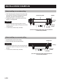
INSTALLATION EXAMPLES
When installing to a wooden ceiling
1 Drill matching holes through the reinforcing
plate and the ceiling in the proper locations
and then pass bolts through the holes.
2 Tighten the bolts to secure the reinforcing
plate to a ceiling beam.
Cautions
• Make sure that the reinforcing plate is strong
enough to bear the weight of the projector and the
ceiling bracket.
• Use M8 bolts (commercially available).
When installing to a concrete ceiling
Reinforcing plate
Washer
Nut and
washer
Bolt (M8)
Ceiling
beam
(Use the reinforcing plate, bolts, nuts and washers
commercially available.)
1 Install anchor nuts in the ceiling.
2 Screw the bolts into the anchor nuts.
Cautions
• Make sure that the anchor nuts are strong enough
to bear the weight of the projector and the ceiling
bracket.
• Use M8 bolts (commercially available).
Anchor nut
Ceiling
Nut and
washer
Bolt (M8)
(Use the anchor nuts, bolts, nuts and washers
commercially available.)

E-11
English
Français
Deutsch
Svenska
Italiano
Español
Nederlands
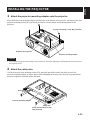
INSTALLING THE PROJECTOR
1 Attach the projector mounting adapter onto the projector.
Align the holes in the mounting adapter with the holes in the bottom of the projector, and then use the four
projector mounting screws (M4, pan head) provided to securely attach the mounting adapter to the
projector.
Caution
• Do not tighten the projector mounting screws excessively. Excessive tightening could damage the mount and cause
the projector to fall.
2 Attach the safety wire.
Use the four safety wire mounting screws (M4, pan head) provided to attach the safety wires to the
projector mounting adapter, as shown below. After tightening the screws, place the wire loops around the
projector’s adjusters, and then tighten the band.
Projector mounting adapter
Projector mounting screws (M4, pan head)
Bottom of the projector
Safety wire mounting screws
(M4, pan head)
Projector mounting adapter
Band
Safety wire

E-12
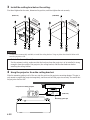
3 Install the ceiling bracket on the ceiling.
First hand-tighten the four nuts, determine the position, and then tighten the nuts securely.
(PMT-L21) (PMT-H25)
Caution
• Use M8 bolts (commercially available) to install the ceiling bracket. Using any bolts other than M8 bolts could
cause the projector to fall.
Note to Dealers and Installers
For the customer’s safety, make sure that the location where the projector is to be installed is strong
enough to bear the weight of the projector, the ceiling bracket, and the other hardware before
installing the ceiling bracket.
4 Hang the projector from the ceiling bracket.
Slide the mounting guide pin all of the way into the notch on the projector mounting adapter. This pin is
only meant to support the projector temporarily, and does not hold the projector securely. Be careful that
the projector does not fall.
(PMT-L21)
Mounting guide pin
Projector mounting adapter
Projection
direction
Projection
direction

E-13
English
Français
Deutsch
Svenska
Italiano
Español
Nederlands
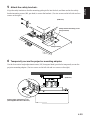
5 Attach the safety brackets.
Align the safety brackets so that the mounting guide pin fits into the hole, and then use the four safety
bracket mounting screws (M4, pan head) to secure the brackets. (Use two screws on the left side and two
screws on the right.)
Safety bracket mounting screw
(M4, pan head)
Safety bracket
(PMT-L21)
6 Temporarily secure the projector mounting adapter.
Use the four vertical angle adjustment screws (M6, hexagonal head) provided to temporarily secure the
projector mounting adapter. (Use two screws on the left side and two screws on the right.)
Vertical angle adjustment screw
(Hand-tighten the other side also.)
(PMT-L21)

E-14
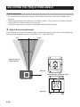
ADJUSTING THE PROJECTION ANGLE
Before adjustment
• Turn the projector on and project an image, following the instructions on the owner’s manual of the
projector.
• Set the appropriate projection method on “Installation” item in “Set up” menu. For the detail about the
setting, refer to the owner’s manual of the projector.
• First, select a projection size using the zoom feature, and then adjust the angle.
1 Adjust the horizontal angle.
Adjust the projector so that the projected image is centered horizontally on the screen, and then tighten the
horizontal angle adjustment screws (2 on the PMT-L21, 4 on the PMT-H25).
10˚
10˚
Maximum angle of
adjustment: ±10˚
(PMT-L21)
(PMT-H25)
Horizontal angle adjustment screws
Left
Right

E-15
English
Français
Deutsch
Svenska
Italiano
Español
Nederlands
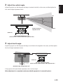
2 Adjust the vertical angle.
Adjust the projector so that the projected image is centered vertically on the screen, and then tighten the
four vertical angle adjustment screws.
3 Adjust the tilt angle.
Adjust the projector so that the projected image is not tilted at all compared to the screen, and then tighten
the four tilt angle adjustment screws.
15˚
15˚
Maximum angle of
adjustment: ±15˚
(PMT-L21)
Vertical angle adjustment screws
(There are also screws located on the opposite side.)
10˚ 10˚
Maximum angle of adjustment: ±10˚
(PMT-L21)
Tilt angle adjustment screws
(There are also screws located on the opposite side.)
If the projector still needs further adjustment, start over from step 1.
After adjustment is completed, make sure that the projector is secured in place.
Top
Bottom

E-16
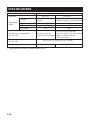
SPECIFICATIONS
Product Name Ceiling Mount Bracket
Model No. PMT-L21 PMT-H25
Height
789 to 1359 mm (31-1/16 to 53-1/2 inch)
(variable in 30 mm (1-3/16-inch) steps)
Vertical angle ±15˚ ±15˚
Horizontal angle ±10˚ ±10˚
Tilt angle ±10˚ ±10˚
Dimensions of ceiling bracket
(W × D × H)
176 × 226 × 789 to 1359 mm
(6-15/16
×
8-7/8
×
31-1/16 to 53-1/2 inch)
(Height is variable in 30-mm
(1-3/16-inch) steps)
Dimensions of adapter
(W × D × H)
Weight 2.2 kg (4 lbs 14 oz) 4.0 kg (8 lbs 13 oz)
• Specifications are subject to change without notice.
362.5 × 179 × 77 mm (14-1/4 × 7 × 3 inch)
Adjustment
range
94 mm (3-11/16 inch)
(fixed)
156 × 196 × 94 mm
(6-1/8
×
7-3/4
×
3-11/16 inch)

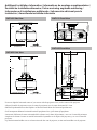
Additional Installation Information / Informations de montage supplémentaires /
Zusätzliche Installationshinweise / Extra anvisning angående montering /
Informazione di installazione addizionale / Información adicional para la
instalación / Aanvullende installatie-informatie
PMT-L21 Front View
192 mm
(7-9/16 inch)
81 mm
(3-3/16 inch)
137 mm
(5-3/8 inch)
111 mm
(4-3/8 inch)
108.5 mm
(4-1/4 inch)
409 mm
(16-1/8 inch)
PMT-H25 Front View
887–1457 mm
(34-15/16–57-3/8 inch)
777–1347 mm
(30-9/16–53 inch)
832–1402 mm
(32-3/4–55-3/16 inch)
Ø8.8 mm
(Ø3/16 inch)
(fully penetrating holes)
111 mm
(4 3/8 inch)
108.5 mm
(4-1/4 inch)
30 mm
(1-3/16 inch)
409 mm
(16-1/8 inch)
PMT-L21 Side View
More than 361 mm
(14-3/16 inch)
159 mm
(6-3/16 inch)
Wall
Projection Direction
122 mm
(4-13/16 inch)
PMT-H25 Side View
Wall
More than 361 mm
(14-3/16 inch)
159 mm
(6-3/16 inch)
Projection Direction
122 mm
(4-13/16 inch)
Be sure to align the horizontal center of your screen with the projector’s lens, not the center of the projector.
Alignez la lentille du projecteur et non le centre du projecteur avec le centre horizontal de l’écran.
Statt der Projektormitte muss das Objektiv auf die horizontale Mitte der Leinwand gerichtet sein.
Se till att anpassa skärmens horisontella mitt till projektorns lins, ej till mitten på projektorn.
Assicurarsi di allineare il centro orizzontale dello schermo con la lente del proiettore, e non con il centro del proiettore.
Asegúrese de alinear el centro en sentido horizontal de la pantalla con el objetivo del proyector, y no con el centro del
proyector.
Lijn het horizontaal midden van uw scherm uit met de lens van de projector, en niet met het midden van de projector.
-
 1
1
-
 2
2
-
 3
3
-
 4
4
-
 5
5
-
 6
6
-
 7
7
-
 8
8
-
 9
9
-
 10
10
-
 11
11
-
 12
12
-
 13
13
-
 14
14
-
 15
15
-
 16
16
-
 17
17


Diğer dillerde
- español: Yamaha PMT-H25 El manual del propietario
- français: Yamaha PMT-H25 Le manuel du propriétaire
- italiano: Yamaha PMT-H25 Manuale del proprietario
- svenska: Yamaha PMT-H25 Bruksanvisning
- čeština: Yamaha PMT-H25 Návod k obsluze
- polski: Yamaha PMT-H25 Instrukcja obsługi
- Deutsch: Yamaha PMT-H25 Bedienungsanleitung
- português: Yamaha PMT-H25 Manual do proprietário
- English: Yamaha PMT-H25 Owner's manual
- dansk: Yamaha PMT-H25 Brugervejledning
- русский: Yamaha PMT-H25 Инструкция по применению
- suomi: Yamaha PMT-H25 Omistajan opas
- Nederlands: Yamaha PMT-H25 de handleiding
- română: Yamaha PMT-H25 Manualul proprietarului