Yamaha PM1D Kullanım kılavuzu
- Kategori
- Ses mikserleri
- Tip
- Kullanım kılavuzu
Bu kılavuz aynı zamanda aşağıdakiler için de uygundur:

EE
PM1D System Software V1.5
Supplementary Manual

PM1D System Software V1.5 Supplementary Manual
2
Copyright
Copying or distributing this manual in part or in whole using any method without the written permission of
Yamaha Corporation is prohibited.
Tr ade marks
Company names and product names are trademarks and registered trademarks of their respective owners.
Symbols such as ® and TM are not explicitly given in this document.
The illustrations and LCD screens as shown in this owner’s manual are for instructional purposes only, and may
appear somewhat different from those on your instrument.

Contents
3
Contents
Additions/changes in V1.5. . . . . . . . . . . . . . . . 4
Changes to the constantly-displayed screen. . 6
Upper part of the display . . . . . . . . . . . . . . . 6
Lower part of the display. . . . . . . . . . . . . . . . 8
DUAL CONSOLE mode added . . . . . . . . . . . . 11
About Dual Console mode . . . . . . . . . . . . . 11
About scene/library memories. . . . . . . . . . . 13
About the console shutdown function. . . . . 14
DUAL CONSOLE screen . . . . . . . . . . . . . . . 14
Connections in Dual Console mode . . . . . . 17
Establishing communication between con-
soles . . . . . . . . . . . . . . . . . . . . . . . . . . . . . 18
Transmitting only the necessary scenes / li-
braries. . . . . . . . . . . . . . . . . . . . . . . . . . . . 21
Limitations of Dual Console mode. . . . . . . . 21
Powering-off the consoles . . . . . . . . . . . . . . 26
Cascade connections . . . . . . . . . . . . . . . . . . . 27
About cascade connections. . . . . . . . . . . . . 27
CASCADE screen. . . . . . . . . . . . . . . . . . . . . 27
Cascade connections . . . . . . . . . . . . . . . . . 29
Establishing a cascade connection. . . . . . . . 31
Cautions when using cascade connection . . 33
Using GPI (General Purpose Interface) . . . . . 35
GPI screen. . . . . . . . . . . . . . . . . . . . . . . . . . 36
Using GPI IN . . . . . . . . . . . . . . . . . . . . . . . . 40
Using GPI OUT . . . . . . . . . . . . . . . . . . . . . . 41
Fader Start function . . . . . . . . . . . . . . . . . . . . 42
FADER START screen . . . . . . . . . . . . . . . . . . 43
Using the Fader Start function. . . . . . . . . . . 45
Tap Tempo function. . . . . . . . . . . . . . . . . . . . 51
Added functions in the USER DEFINE screen 52
Input channel panel assignments . . . . . . . . . 52
PANEL ASSIGN screen. . . . . . . . . . . . . . . . . 52
Switching the panel assign setting . . . . . . . 55
Horizontal pair and vertical pair . . . . . . . . . . 56
Mix minus. . . . . . . . . . . . . . . . . . . . . . . . . . . . 58
New functions in the PAN/ROUTING screen 58
Using mix minus . . . . . . . . . . . . . . . . . . . . . 59
Cautions regarding mix minus . . . . . . . . . . 60
Job select . . . . . . . . . . . . . . . . . . . . . . . . . . . . 61
Mix send on/off . . . . . . . . . . . . . . . . . . . . . 61
Mix send point . . . . . . . . . . . . . . . . . . . . . . 62
Mix send level. . . . . . . . . . . . . . . . . . . . . . . 62
Mix send pan/balance. . . . . . . . . . . . . . . . . 63
Auto Store function . . . . . . . . . . . . . . . . . . . . .64
Using Auto Store from the screen . . . . . . . . 64
Using Auto Store from the [STORE] switch . .65
Global Paste function . . . . . . . . . . . . . . . . . . .66
GLOBAL PASTE screen . . . . . . . . . . . . . . . . 66
Using the Global Paste function . . . . . . . . . .68
Parameter control via CONTROL CHANGE and
NRPN . . . . . . . . . . . . . . . . . . . . . . . . . . . . . . .71
MIDI CTRL CHANGE screen . . . . . . . . . . . . 71
Using CONTROL CHANGE / NRPN messag-
es to record/play parameter changes . . . . .74
Manual Fading function . . . . . . . . . . . . . . . . 76
New functions in the FADE TIME screen . . . 76
Using Manual Fading (1) . . . . . . . . . . . . . . 76
Using Manual Fading (2) . . . . . . . . . . . . . . .78
Unit name . . . . . . . . . . . . . . . . . . . . . . . . . . . .79
UNIT NAME screen. . . . . . . . . . . . . . . . . . . 79
Naming a unit/port . . . . . . . . . . . . . . . . . . .81
Matrix send shortcuts . . . . . . . . . . . . . . . . . . .82
DCA mute indicator . . . . . . . . . . . . . . . . . . . . 85
Oscillator improvements . . . . . . . . . . . . . . . . .86
Improvements in the OSCILLATOR screen . 86
Improvements in the INPUT PATCH / OUT-
PUT PATCH screens . . . . . . . . . . . . . . . . . . . .89
USB PC (computer) connection . . . . . . . . . . 89
Automatic scrolling in the CH to MIX screen
and MATRIX/ST ROUTING screen. . . . . . . . 90
ON/OFF button for COMM IN . . . . . . . . . . . .91
Added functions in the PREFERENCE screen. .92
Supplementary explanation for existing func-
tions . . . . . . . . . . . . . . . . . . . . . . . . . . . . . . . 93
Scene Memory/Effect Library to Program
Change Table. . . . . . . . . . . . . . . . . . . . . . . . .94
MIDI control change NRPN (Non Registered
Parameter Number) assignment table . . . . 94
MIDI control change parameter assignment
table . . . . . . . . . . . . . . . . . . . . . . . . . . . . . . . .97
MIDI Data Format . . . . . . . . . . . . . . . . . . . . .100

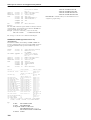
PM1D System Software V1.5 Supplementary Manual
4
This manual explains the functionality that has been added or changed in PM1D system software V1.5. Please
refer to the original manual in conjunction with this manual.
*In cases where the display of the console (CS1D) differs from the screen of the PM1D Manager application program,
explanations that apply only to PM1D Manager are indicated as [PM1D Manager].
Additions/changes in V1.5
This section briefly summarizes the additions and changes in PM1D system software V1.5. For details on each
function, refer to the appropriate page.
■
Changes to the constantly-displayed
screen
Major changes have been made to the items that are
always shown in the top and bottom of the screen
(
→
p.6).
■
New DUAL CONSOLE mode
As an operation mode of the PM1D system, a DUAL
CONSOLE mode has been added, allowing two con-
soles to be used with one system (
→
p.11).
■
Cascade connection
Two systems can now be cascade-connected. A cas-
cade-connected system can send any bus output to
the same bus of the other system (
→
p.27).
■
GPI connector is now enabled
The D-sub 25 pin GPI connector provided on the
console and engine can now be used to input/output
eight channels of control signals (
→
p.35).
■
REMOTE connector is now enabled
The D-sub 9-pin REMOTE connector of the console
and engine can now be used to control a recorder or
other device (
→
p.35).
■
Fader Start function
You can now specify that various commands be
transmitted from an assigned connector when the
level of a specified channel is raised above –60 dB or
lowered to –
∞
dB (
→
p.42).
■
Tap tempo function
A “tap tempo” function has been added, allowing
you to manually set the TEMPO parameter of an
internal effect by tapping an external switch con-
nected to the GPI connector (
→
p.51).
■
Expanded USER DEFINE functions
In conjunction with the addition of various func-
tionality, the user-definable functions have been sig-
nificantly expanded (
→
p.52).
■
Input channel panel assignment can
now be selected
The input channels assigned to INPUT blocks 1–4 of
the console can now be freely specified in blocks of
twelve consecutive channels. Similarly, the ST IN
channels assigned to ST IN blocks 1–2 can also be
assigned in blocks of two adjacent channels (
→
p.52).
Also, the DISPLAY SELECT section of the TRACK-
ING RECALL screen now has an INPUT [PANEL]
button that causes the current panel assignment state
to be displayed in the screen.
■
New pairing mode
In addition to the existing pairing mode in which
adjacent input channels 1+2, 3+4, ... can be paired,
you can now use “vertical pairing mode” in which
input channels 1+49, 2+50 ... are paired. This mode
allows you to use a single fader as if it were a stereo
fader (
→
p.56).
■
Mix minus setting
A MIX MINUS button has been added to the CH to
MIX screen of the PAN/ROUTING function. This
button provides a simple way to subtract only a spe-
cific channel from the signal that is being sent to a
certain MIX bus. This is useful when a performer or
announcer wishes to monitor the sound without his
own voice (
→
p.58).
■
Job select
Now you can move the cursor to a parameter and
press the [SHIFT] + [ENTER] keys to access a
popup-menu that lists the jobs available for that
parameter. The cursor will turn yellow to indicate
parameters for which you can use this function
(
→
p.61).
■
Auto Store function
When storing a scene, you can now use an “Auto
Store function” that automatically selects the unit,
patch, or name library number and title (
→
p.64).
■
Global Paste function
Using the new “Global Paste function,” the settings of
any channel or parameter in the current scene can be
copied and pasted to one or more scenes in scene
memory. This is a convenient way by which changes
in the current scene can be applied to previously-
stored scenes (
→
p.66).

Additions/changes in V1.5
5
■
Operate parameters via control
changes
Now you can use MIDI control changes to remotely
control PM1D parameters from an external device,
or transmit console operations as control changes
(
→
p.71).
■
Manual fading
A new “Manual Fading” function has been added.
When recalling a scene for which a fade time has
been set, you can now use the [DATA] encoder to
fade in the positive or negative direction. This is con-
venient when you want to vary the volume in con-
junction with action on stage (
→
p.76).
■
Unit name
You can now assign a unit name to each port of an
input/output unit or card. If necessary, the unit
name of each port can be displayed in the field in
which the short name of an input channel was shown
in the screen (
→
p.79).
■
Matrix send shortcut
The send level from a MIX channel or STEREO A/B
channel to a MATRIX channel can now be controlled
from a panel encoder (
→
p.82).
■
DCA mute indicator
When you mute a DCA group, the [ASSIGN DCA]
LED of the channels associated with that DCA can
now be made to blink if desired. This is convenient
when you want to know which channels are actually
being muted (
→
p.85).
■
Improved oscillator
The oscillator now lets you use two sine waves simul-
taneously. You can specify the frequency and level for
each, and output them independently to odd-num-
bered / even-numbered channels (
→
p.86).
■
Improvements in the INPUT PATCH /
OUTPUT PATCH screens
The unit name of each port is now displayed in the
UNIT PATCH / OUTPUT PATCH screens. Vertical
and horizontal red lines can also indicate the cur-
rently selected grid (
→
p.89).
■
USB connection to a PC
In addition to the serial connection supported on
earlier versions, you can now use a USB connection
to connect the PM1D to a PC (
→
p.89).
■
Improved operation in the CH to MIX
and MATRIX/ST ROUTING screens
Cursor movement now follows scrolling in the CH to
MIX function of the PAN/ROUTING function and
in the MATRIX/ST ROUTING screen of the
MATRIX/ST function (
→
p.90).
■
ON/OFF button added to COMM IN
The COMM IN function can now be turned ON/
OFF independently (
→
p.91).
■
Additional functions in the PREFER-
ENCE screen
A variety of setting items have been added in the
PREFERENCE screen (
→
p.92).
■
Channel selection can now be sepa-
rately specified for the AUTO DISPLAY
function (SELECTED CH ON/OFF but-
ton)
One of the AUTO DISPLAY functions automatically
moves the cursor to the corresponding parameter
when you switch the channel that is being operated.
In the PREFERENCE screen AUTO DISPLAY sec-
tion, this function can now be switched on/off inde-
pendently of the other AUTO DISPLAY items
(
→
p.92).

PM1D System Software V1.5 Supplementary Manual
6
Changes to the constantly-displayed screen
In PM1D system software V1.5, the following changes have been made to the items that are always shown in
the top and bottom of the console display.
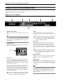
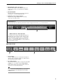
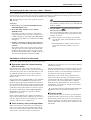
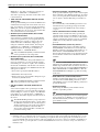
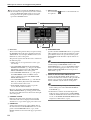
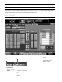
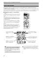
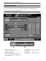
Upper part of the display
1
DISPLAY FUNCTION
Shows the currently selected function as an abbrevia-
tion.
Hint
Click this to switch between the FUNCTION MENU
screen and the screen of the currently selected func-
tion. (Equivalent to the MENU button of the previ-
ous version.)
2
CONNECTION
Indicates the status of the connections between the
engine(s) and console(s).
•
Console 1/2
If DUAL CONSOLE is selected as the console opera-
tion mode (SYSTEM CONFIGURATION in the
SYSTEM CONNECTION screen, etc.), this indicates
whether that console (CS1D) is specified as console 1
or as console 2 (
→
p.19).
The color of this numeral will depend on how CAS-
CADE is set for the operation mode. In the case of
CASCADE OFF or CASCADE ON [MASTER], this
numeral will be white on a black background. If
CASCADE ON [SLAVE], this numeral will be black
on a white background.
If cascade communication between the systems
cannot be established even though CASCADE
ON is selected, this numeral will blink.
•
DUAL
If DUAL CONSOLE is selected as the operation
mode for the console, “DUAL” will be displayed here
(
→
p.19).
If communication between the consoles cannot
be established even though DUAL CONSOLE
mode is selected, an X mark will be displayed
over the “DUAL” indication.
•
Engine A/B
If the PM1D system is being used in mirror mode,
this indicates which engine (A or B) is currently
enabled, and the number of usable channels. The
enabled engine is shown on a green background. You
can also click this button to switch between engines
A/B.
If the engine that should be enabled is not oper-
ating normally, or if the connection has been
broken, an X mark will be displayed over the A
or B symbol.
3
PANEL STATUS
Indicates the current panel assignment (the channel
numbers assigned to the INPUT block / ST IN
block).
4
FADER FLIP
Indicates the state of the FADER FLIP switch located
on the console panel (i.e., whether [MIX] or [CH] is
on). You can also use these buttons to switch [MIX]
and [CH].
Hint
If the FADER FLIP LINK button is turned off in the
UTILITY function PANEL ASSIGN screen (a new
screen added in V1.5), fader flip can be switched
independently for INPUT blocks 1/2 (left) and 3/4
(right) (
→
p.54).
1 2 3 5 6
4
Console 1/2
DUAL Engine A/B

Changes to the constantly-displayed screen
7
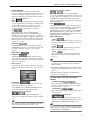
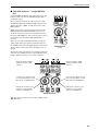
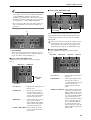
5 SCENE MEMORY
Displays the number and title used when most
recently recalling/storing the currently selected scene
memory. Depending on the state of the scene, the
following symbols may be displayed in the margin of
the SCENE MEMORY field.
• EDIT
This symbol will be displayed if you edit a parameter
of a scene, patch, unit, or name after recalling/storing
a scene memory. When you recall/store a scene
memory, this symbol will disappear. (However, it
may not disappear if Recall Safe is turned on.)
• TC
This symbol will be displayed if the EVENT
RECALLING button is set to ENABLE in the TC
EVENT screen. You cannot rewrite scene memories
or patch/unit/name libraries while this symbol is dis-
played. This means that you will also be unable to use
functions such as store, undo store, link on/off, title
editing, sort, or load.
• PREVIEW
In PREVIEW mode, this symbol will be displayed.
In PREVIEW mode, the scene number and title will
be displayed in white characters on a red back-
ground.
• READ ONLY
• PROTECT
The READ ONLY symbol will be displayed if the
scene currently selected for store/recall is read-only
(00.0-00.9). The PROTECT symbol will be displayed
if protect is turned on.
6 Other symbols
The following symbols will be displayed at the upper
right of the display according to the state of the con-
sole.
• SOLO/CUE
According to the current solo or cue state, this area
will display the following symbols:
SOLO, EFFECT CUE, SUBIN CUE, INPUT CUE,
DCA CUE, OUTPUT CUE, KEY IN CUE
• TB/OSC (Talkback / Oscillator)
The TB symbol will be displayed if talkback is on,
and the OSC symbol will be displayed if the oscillator
is on.
Hint
If the above operations occur simultaneously, they
will be displayed in the order of TB → OSC.
• COMM IN (Communication In)
If COMM IN is turned on in the MONITOR A
screen, the COMM IN symbol will be displayed on a
green background. In addition if a port is assigned to
COMM IN, the background of this symbol will
change to red when the input signal passes through
the COMM IN gate.
• LCR
The LCR symbol will be displayed if LCR is turned
on for at least one input channel or output channel
(in the LCR screen of the PAN/ROUTING or
MATRIX/ST function). In addition if the CENTER
BUS CONTROL button (in the LCR screen of the
PAN/ROUTING or MATRIX/ST function) is on, the
LCR [B] symbol will be displayed.
• RS422, MIDI, BUSY
- RS422
This symbol will be displayed when a response to a
transport command sent via the RS422 connector
is received.
- MIDI
This symbol will be displayed when a program
change or control change is received.
- BUSY
This symbol will be displayed during startup or
while internal memory or a PC card file is being
accessed.
Hint
• If the above states occur simultaneously, they will
be displayed in descending priority of RS422 →
MIDI → BUSY.
• The RS422 and MIDI symbols will remain visible
for approximately 200 msec after reception is com-
pleted.
• The BUSY symbol will disappear immediately
when access is completed.
• MANUAL FADE, AUTO FADE, TRACKING
ENABLE
- MANUAL FADE
This symbol will be displayed if Manual Fading is
enabled (even if a fade operation is not actually
being performed) (→p.76).
- AUTO FADE
This symbol will be displayed while Auto Fading is
being executed.
- TRACKING (Tracking Recall)
This symbol will be displayed if tracking recall is
enabled (the TRACKING RECALL button is set to
ENABLE in the TRACKING RECALL screen).
Hint
If the above states occur simultaneously, they will be
displayed in descending priority of MANUAL FADE
→ AUTO FADE → TRACKING.

PM1D System Software V1.5 Supplementary Manual
8
[PM1D Manager]
In PM1D Manager, the following information will be displayed instead of 3 PANEL STATUS and 4 FADER
FLIP described on page 6.
1 Connection status
This area of the PM1D Manager screen will indicate
the status of the connection between the PC and the
console or engine.
• ........... Indicates that a cable is con-
nected between the PC and
console or engine, but com-
munication has not been
established.
• ........... Indicates that a cable is con-
nected between the PC and
console or engine, and that
communication has been
established. In this state, the
PM1D system can be con-
trolled from the computer.
• ...........Indicates that either the
cable is not connected,
or that the other device
is not powered-on.
2 Connection destination / connection
method
In OFFLINE or ONLINE states, this area will
show a graphic that indicates the connection des-
tination (console or engine), and the connector
(COM port name or USB port name) that is
selected in the Communication Port (Option
menu) of Communication Setup.
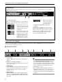
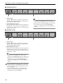
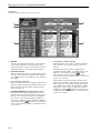
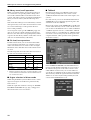
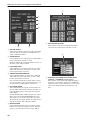
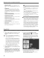
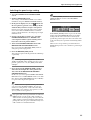
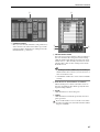
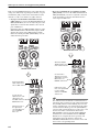
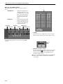
Lower part of the display
The lower part of the display is divided into the following four parts. Click the √/® buttons at the lower left of the
screen to switch the items that are shown.
■ CONSOLE STATUS
1 Select buttons
Click the √/® buttons to switch the items that are
displayed.
2 IN SEL (Selected input channel)
Indicates the input channel that is currently selected
by the [SEL] switch.
3 NAME MODE
Selects whether the display will show the short name
of the input channel (CH NAME), or the name of
the unit assigned to that input channel (UNIT
NAME) (→p.79).
4 MODULE FLIP
Indicates the on/off state of the MODULE [FLIP]
switch in the SELECTED INPUT CHANNEL block.
You can also click this button to change the module
flip setting.
Hint
• If the PATTERN CHANGE button is turned on in
the MODULE FLIP BUTTON MODE section of
the UTILITY function PANEL ASSIGN screen (a
new screen added in V1.5), the indications of these
buttons will change to “PATT.” In this case, they are
used to switch channel assign patterns for the
INPUT block (→p.52).
• If the MODULE FLIP / PATTERN CHANGE
LINK button in the same screen is turned off, set-
tings for module flip and patterns can be made
independently for the left and right INPUT blocks
(→p.54).
21
2 3 4 65 71

Changes to the constantly-displayed screen
9
5 MIX SEND NO. (Mix send number)
Indicates the number of the MIX bus that is cur-
rently selected as the send destination for INPUT
blocks 1–4.
6 MASTER FADER
Indicates the function that is currently assigned to
DCA faders 1–12 (DCA GROUP block).
7 OUT SEL (Selected output channel)
Indicates the output channel that is currently
selected by the [SEL] switch.
[PM1D Manager]
In PM1D Manager, the following information will be displayed instead of 4–6 described above.
1 DIRECT RECALL / MUTE MASTER
According to the setting of the RECALL button or
MUTE button, these buttons either directly recall
twelve previously-assigned scenes, or switch mute
groups 1–12 on/off. These buttons have the same
function as SCENE MEMORY [1]–[12] switches on
the panel of the console.
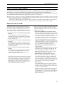
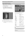
■ USER DEFINE
1 Select buttons
Click the √/® buttons to switch the items that are
displayed. If you click the middle, you will return to
the CONSOLE STATUS display.
2 User define buttons
These list the functions that are assigned to the USER
DEFINE [1]–[8] switches in the USER DEFINE
block of the console. You can also click a button to
execute the corresponding function.
Hint
Functions for the USER DEFINE [1]–[8] switches
can be assigned in the UTILITY function USER
DEFINE screen.
1
1 2

PM1D System Software V1.5 Supplementary Manual
10
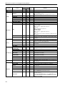
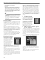
■ CONSOLE GPI IN
1 Select buttons
Click the √/® buttons to switch the items that are
displayed. If you click the middle, you will return to
the CONSOLE STATUS display.
2 Console GPI IN test buttons
These buttons list the functions that are assigned via
the GPI connector of the console to GPI IN (ports 1–
8). You can also click a button to test the correspond-
ing function (→p.40).
Hint
• Functions for the GPI IN test buttons can be
assigned in the MIDI/GPI/TC function GPI screen.
• Even if you are not using the GPI port, you can use
these buttons in place of the USER DEFINE
switches by assigning functions to the GPI IN test
buttons.
■ ENGINE GPI IN
1 Select buttons
Click the √/® buttons to switch the items that are
displayed. If you click the middle, you will return to
the CONSOLE STATUS display.
2 Engine GPI IN test buttons
These buttons list the functions that are assigned via
the GPI connector of the engine to GPI IN (ports 1–
8). You can also click a button to test the correspond-
ing function (→p.40).
Hint
• Functions for the GPI IN test buttons can be
assigned in the MIDI/GPI/TC function GPI screen.
• Even if you are not using the GPI port, you can use
these buttons in place of the USER DEFINE
switches by assigning functions to the GPI IN test
buttons.
Since the GPI IN of the engine can be controlled
only from console 1, the GPI IN test buttons will
not be displayed in DUAL CONSOLE mode if con-
sole 2 is specified.
However in PM1D Manager, the display is not
restricted even if console 2 is specified in DUAL
CONSOLE mode when OFFLINE.
1 2
1 2

DUAL CONSOLE mode added
11
DUAL CONSOLE mode added
As an operation mode of the PM1D system, version 1.5 adds Dual Console mode, in which two console are
used by one system. The functionality and operation of Dual Console mode is explained below.
In the following explanation, functions and operations that apply only to console 1 are indicated as [Console
1], and functions and operations that apply only to console 2 as [Console 2].
If the console (CS1D) you are using was manufactured before June 2002, you may be unable to select Dual Console
mode even if connections are correct. In this case, you will need to have a gate array rewritten in order to use Dual
Console mode. Please contact your Yamaha dealer.
It is necessary to have the gate array rewritten only if you wish to use Dual Console mode. If you are using the sys-
tem in other modes, rewriting is not necessary, and you may continue using the system without change.
About Dual Console mode
Dual Console mode is a mode in which two consoles
(CS1D) are used in a single PM1D system. In this mode,
two consoles share one (in standard mode) or two (in
mirror mode) engines (DSP1D-EX {DSP1D}). Here are
some examples of how Dual Console mode can be used:
• Use two consoles to control the main mix and mon-
itor mix
In this application, the same input channels are
patched to the panels of both consoles. One engineer
controls the main mix, and another engineer con-
trols the monitor mix.
• Use two consoles to control the same mix from two
locations
In this application, two consoles are placed in sepa-
rate locations (for example one near the stage and
the other in the audience seating), and two engineers
control the same mix.
• Use two consoles to control 96 channels simulta-
neously
In this application, input channels 1–48 are patched
to one console, and input channels 49–96 to the
other console, allowing one or more engineers to
control 96 channels simultaneously.
In Dual Console mode, the console that is connected
to the engine will operate as the master unit, and the
other console will operate as the slave unit. However,
in order to avoid confusion with the master/slave
relationship in “engine cascade” (described later in
this document), we refer to the master unit as “con-
sole 1,” and the slave unit as “console 2.”
Console 1 and console 2 differ in the functions they can
control, and in the order of priority when operations
overlap. The differences between consoles 1 and 2 can be
summarized as follows.
• Items that are linked between consoles 1 and 2
In general, changes that you make to the mix param-
eters in the current scene are linked between consoles
1 and 2. (An operation on one console will be
reflected by the other.) Operations of console 2 will
not nullify operations of console 1. Even if differ-
ences occur between the states of console 1 and con-
sole 2, the engine will always be set according to
console 1. If a difference occurs between parameters
that should be linked, you can select whether to copy
all scenes and all libraries when connection occurs,
or to copy them as desired after connection.
• Items that are operated independently between
consoles 1 and 2
Channel selections by the [SEL] switches, changes in
panel layout such as fader flip or module flip, and
screen switching by the function switches are not
linked between consoles. These operations can be
made independently on each console.
• Items that can be operated only by console 1
Most operations that affect the core of the system,
such as switching between engines, switching the
word clock master, and changing the connections
between components, can be performed only by con-
sole 1. The settings of most items can be viewed on
the console 2 screen, but cannot be modified.
• PC connection
A PC (PM1D Manager) can be connected only to
console 1 or to the engine. It cannot be connected to
console 2. Nor is it possible to connect and use two
or more PCs simultaneously.
Whether a parameter is linked when operated, and
the priority between consoles 1 and 2, will differ
depending on the screen. The table on the following
page summarizes the operation of each screen in
Dual Console mode.

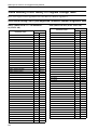
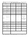
PM1D System Software V1.5 Supplementary Manual
12
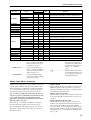
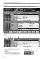
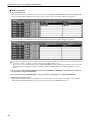
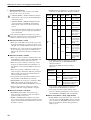
Function Screen
Linked
Indepen-
dent
Remarks
1
→21↔2
EFFECT
O
GEQ
O
SCENE
MEMORY
q
Only the trigger for number and store/recall operations is
transmitted and received.
SORT-related settings can be operated only on console 1
RECALL SAFE
O
FADE TIME
O
DIRECT RECALL
O
TRACKING RECALL
O
GLOBAL PASTE
O
MIDI/GPI/TC
MIDI PGM CHANGE
O
MIDI CTRL CHANGE
O
GPI
q
• GPI IN settings
Console 1 or PC:
Only console 1 / engine port can be set
Console 2:
Only console 2 port can be set
• GPI OUT settings
Console 1 or PC:
Only console 1 / engine port can be set
Console 2:
Only console 2 port can be set. However, engine port can
be viewed
TC EVENT
O
FADER START
O
Cannot be set on a PC connected to a system that includes
a console
UTILITY
PREFERENCE
O
USER DEFINE
O
From system software 1.5, this can be set/operated indepen-
dently for consoles 1 and 2 and the PC
LOAD / SAVE
O
There are limitations on the parameters that can be loaded
by console 2
PANEL ASSIGN
O
PAIR MODE
O
SYS/W.CLOCK
SYSTEM
CONNECTION
q
Buttons that switch the wiring of console 2 itself can also be
operated from console 2
DUAL CONSOLE
O
CASCADE
O
INPUT UNIT
q
Virtual units can be created only from console 1.
Unit parameters are linked.
OUTPUT UNIT
q
Virtual units can be created only from console 1.
Unit parameters are linked.
WORD CLOCK
O
DITHER
O
UNIT NAME
O
METER
q
METERING POINT and PEAK HOLD can be operated only
from console 1
MON/CUE
TALKBACK
q Only TB OUT is in common
OSCILLATOR
O The two consoles share one 2CH set of oscillators.
2TR IN
q
Settings other than INPUT CONSOLE can also be operated
from console 2
ST OUT DIGITAL
O
MONITOR A
O
MONITOR B
—— —
Cannot be operated, since in Dual Console mode, this func-
tions as MONITOR A of the other console
CUE/SOLO
q
Cue is independent, solo function on/off can be operated
only from console 1
Linked if the CUE MODE button is set to SOLO ON, or if in
the SYS/W.CLOCK function DUAL CONSOLE screen CUE
ON/OFF is turned ON.

DUAL CONSOLE mode added
13
• Linked (1→2).............Screens in which the con-
sole 1/2 settings are linked.
However, they can be oper-
ated only by console 1.
• Linked (1↔2).............Screens in which the con-
sole 1/2 settings are linked.
They can be operated from
either console 1 or 2.
• Independent...............Screens in which settings
can be made independently
by consoles1 and 2.
• O ..................................Indicates that all parame-
ters in the corresponding
function/screen will operate
as indicated (independent,
linked 1→2, or linked
1↔2).
•
qq
qq
.................................Indicates that some param-
eters in this function/screen
are exceptions, and operate
other than indicated.
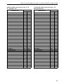
About scene/library memories
When a scene or library is stored or recalled on one con-
sole, the other will follow this operation. However, this
simply means that a command of “recall scene number
***.*” is transmitted to the other console; the result of
the store/recall is not conveyed to the other console.
Thus, in order to completely synchronize the two con-
soles, it is necessary to match the current memory (the
scene, patch, units, names currently shown in the
panel), the scene memories and libraries that are used,
and some of the setup data.
If this data does not match, scene/library recall opera-
tions may cause the settings of the current scene to
become completely different between the two consoles.
Data can be synchronized between the two consoles in
the following ways.
• Tr ansfer all data
In this method, all data is transmitted via the CON-
TROL I/O connector from console 1 to console 2.
You can perform this operation in a single step when
you initiate Dual Console mode.
• Tr ansfer only necessary data
In this method, only the scenes and libraries that will
be used are manually transmitted from console 1 to
console 2.
• Tr ansfer all data via memory card
In this method, all data of console 1 is saved on a
memory card, and this data is then loaded into con-
sole 2. To use this method, use the LOAD/SAVE
screen of console 1 to save all data on a memory card,
then insert that card into console 2 and load the data.
(For details, refer to “CS1D Reference Manual (Soft-
ware),” p.40.)
OUT PATCH
OUTPUT PATCH
O
If a discrepancy occurs between the patching when a scene/
unit is recalled, the patching of console 1 will take priority
INSERT PATCH
O
INSERT POINT
O
INSERT VIEW
O
NAME
O
OUT INSERT
O
OUT EQ
O
OUT COMP
O
OUT DELAY
O
OUT DCA MUTE
O
MATRIX/ST
O
OUT CH VIEW
O
IN PATCH
INPUT PATCH
O
If a discrepancy occurs between the patching when a scene/
unit is recalled, the patching of console 1 will take priority
DIRECT OUT PATCH
O
INSERT PATCH
O
INSERT/DIRECT POINT
O
INSERT/DIRECT VIEW
O
NAME
O
HA/INSERT
O
IN EQ
O
IN GATE/COMP
O
IN DELAY
O
IN DCA/MUTE
O
PAN/ROUTING
O
INPUT CH VIEW
O
Function Screen
Linked
Indepen-
dent
Remarks
1→21↔2

PM1D System Software V1.5 Supplementary Manual
14
About the console shutdown function
A Shutdown function has been added to keep current memory from being modified in Dual Console mode.
In Dual Console mode, powering-off either console may modify the current memory of the other console or
the engine, but by shutting-down the console before powering it off, you can prevent current memory from
being modified.
For the procedure, refer to page 26.
• This shutdown function is necessary only in Dual Console mode. If you are not operating in Dual Console mode,
the SHUTDOWN button (→p.26) will not be displayed.
• If you power-off the console without performing this procedure as described, the current memory used by the
other console or the engine may be modified. However, settings other than current memory (i.e., scene memory,
the various setup memories and libraries) will not be affected. Thus, if you have stored the current memory to a
scene, you can re-recall that scene to recover from an accidental power-off that occurred without performing the
shutdown.
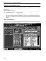
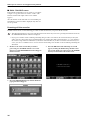
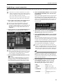
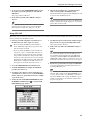
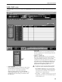
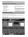
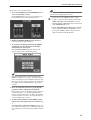
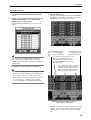
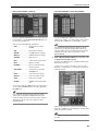
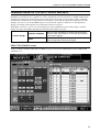
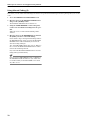
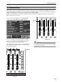
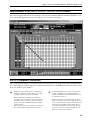
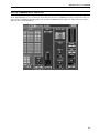
DUAL CONSOLE screen
PM1D system software V1.5 adds a DUAL CONSOLE screen to the SYS/W.CLOCK function. In this screen you can make
settings and perform operations for Dual Console mode.

DUAL CONSOLE mode added
15
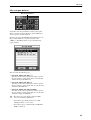
1 SYSTEM CONFIGURATION
Indicates the current operation mode and cascade
mode of the PM1D system. Click the button to
open the SYSTEM CONFIGURATION popup win-
dow, where you can switch the operation mode and
cascade mode.
Hint
The SYSTEM CONFIGURATION field is displayed
in the SYS/W.CLOCK function SYSTEM CONNEC-
TION screen, DUAL CONSOLE screen, and CAS-
CADE screen (newly added in version 1.5). All of
these represent the same setting.
2 DUAL CONSOLE LINK (DUAL CONSOLE mode
link settings)
Here you can select whether cue operation and talk-
back-controlled dimmer operation will be linked.
If the CUE ON/OFF LINK button is on, operations
of the [CUE] switches, EFFECT CUE, SUB IN CUE,
and gate KEY IN CUE will be linked.
If the TALKBACK DIMMER ON/OFF LINK button
is on, turning talkback on from one console will
attenuate the monitor signal on the other console as
well.
Note that the TALKBACK DIMMER ON/OFF
LINK button links the dimmer operation; it does
not link talkback on/off operation. The amount of
attenuation when the dimmer is on can be adjusted
independently in the MONITOR A screen of each
console.
1
2

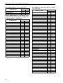
PM1D System Software V1.5 Supplementary Manual
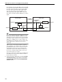
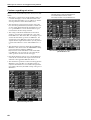
16
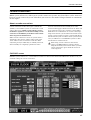
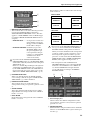
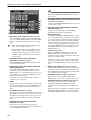
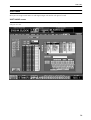
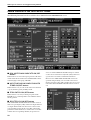
[Console 1]
The following screen appears only on console 1.
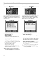
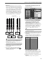
3 UPDATE
Each time you click this button, the current memory,
scene memories/libraries, and setup data will be
compared between console 1 and console 2, and the
ALL DATA STATUS (4) display will be updated.
4 ALL DATA STATUS
This area displays the result of comparing the data of
console 1 and 2. If all data is identical, this will indi-
cate “SAME.” If there is any difference, this will indi-
cate “DIFF.”
5 Scene memories / libraries
This area displays the result of comparing each scene
memory and library. You can click the buttons at the
left to select the items that will be displayed in the
library data list (7).
6 CURRENT MEMORY (Current memory status)
This indicates the result of comparing the current
memory (the scene currently reflected by the panel,
patches, units, and names). If these are all identical
for consoles 1 and 2, this will indicate “SAME.” If
there are any differences, this will indicate “DIFF.” If
you click the COPY button located in the cen-
ter, the current memory will be copied from console
1 to console 2.
7 Scene memory / library data list
This displays the scene memory / library data that is
selected by the scene memory / library status (5)
buttons.
The ALL field at the top of the list will indicate
“SAME” if all data matches, or “DIFF” if there is any
difference. If you click the COPY button
located in the center, the entire contents of the
selected scene memory or library will be copied from
console 1 to console 2.
The lower lines of the list show the contents of the
selected scene memories / libraries for each console.
If the contents of each number match, this will indi-
cate “SAME.” If they differ, this will indicate “DIFF.”
Only while a scene memory is displayed in the list,
clicking the COPY button located in the cen-
ter will copy the contents of that scene memory from
console 1 to console 2.
7
6
5
3
4

DUAL CONSOLE mode added
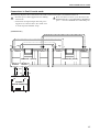
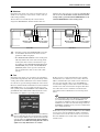
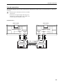
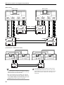
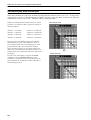
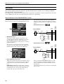
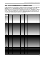
17
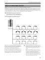
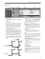
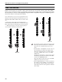
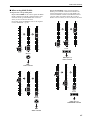
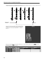
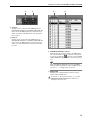
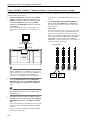
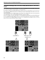
Connections in Dual Console mode
The following diagrams show connections between the consoles and engine(s) in Dual Console mode.
• You must power-off all equipment before making
connections.
• Connections for input/output units and power
supplies are not discussed here. For details, refer
to “CS1D Operation Manual, Setup.”
Please note that on console 2 you will connect the
DIGITAL I/O lines to the DIGITAL I/O ENGINE A
ports — not to the DIGITAL I/O CONSOLE ports.
[Standard mode]
IN OUT
IN OUT
INOUT
1212 121212
12
121212
12 12
12
IN OUT
ENGINE A
(DSP1D-EX{DSP1D})
CONTROL
I/O
CONSOLE
I/O
CONSOLE 1 (CS1D)
CONTROL I/O
CONSOLE
CONTROL I/O
ENGINE A
DIGITAL I/O
ENGINE A
DIGITAL I/O
CONSOLE
CONSOLE 2 (CS1D)
CONTROL I/O
CONSOLE
DIGITAL I/O
ENGINE A

PM1D System Software V1.5 Supplementary Manual
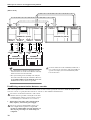
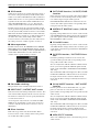
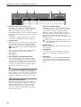
18
[Mirror mode]
Hint
• The dashed lines in the above diagram are spare
connections for use in the event that the currently-
valid connectors become unusable.
• The system will operate normally even with just
the connections shown by the solid lines. However,
we recommend that you also make the spare con-
nections shown above whenever possible.
Connect each device to the identically-numbered (1
or 2) connector on each device. The system will not
operate correctly if you connect differently-num-
bered connectors.
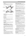
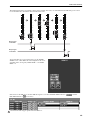
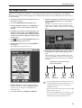
Establishing communication between consoles
This section explains how to select Dual Console mode on each console, specify the console to which the engine is con-
nected as “console 1,” specify the other console as “console 2,” and establish communication.
In order to use Dual Console mode, each console
number must be specified correctly. Be aware that
communication will not occur if consoles 1 and 2
are interchanged, or if both are set to console 1.
1. Turn on the power in the order of input/output
units, engine(s), and console power supply.
Incorrect operation while making settings can
cause a high-volume signal to be output. We
strongly recommend that you turn down the vol-
ume of your power amps etc. until settings are
completed.
IN OUT
IN OUT
INOUT
1212 121212
12
121212
12 12
12
IN OUT
ENGINE A
(DSP1D-EX{DSP1D})
CONTROL
I/O
CONSOLE
I/O
CONSOLE 1 (CS1D)
CONTROL I/O
CONSOLE
DIGITAL I/O
CONSOLE
CONSOLE 2 (CS1D)
CONTROL I/O
CONSOLE
IN OUT
INOUT
12
121212
12 12
ENGINE B
(DSP1D-EX{DSP1D})
CONTROL
I/O
CONSOLE
I/O
CONTROL I/O
ENGINE A
DIGITAL I/O
ENGINE A
CONTROL I/O
ENGINE B
DIGITAL I/O
ENGINE B
DIGITAL I/O
ENGINE A

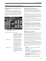
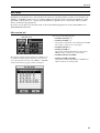
DUAL CONSOLE mode added
19
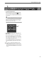
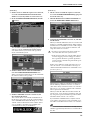
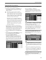
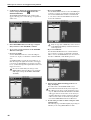
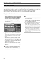
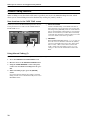
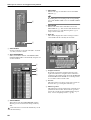
[Console 2]
2. On the console to which the engine is not connected,
access the SYS/W.CLOCK function DUAL CON-
SOLE screen (a newly added screen in version 1.5).
3. In the SYSTEM CONFIGURATION field, click the
button.
The SYSTEM CONFIGURATION popup window
will appear. In the OPERATION MODE SELECT
area of this window you can select the operation
mode of the PM1D system.
4. Click the DUAL button within the CONSOLE sec-
tion of the OPERATION MODE SELECT area.
When you turn the DUAL button on, the CONSOLE
No. buttons will become operable.
5. Click the CONSOLE 2 button to turn it on, and
then click the OK button.
The console will be set to DUAL CONSOLE mode.
In the upper part of the screen, the control number
of the CONNECTION field will change to “2,” and
“DUAL” will be indicated below the number. (How-
ever, an X will be superimposed on DUAL since
communication is not yet established.)
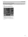
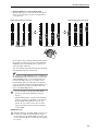
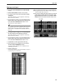
[Console 1]
6. On the console to which the engine is connected,
access the SYSTEM CONFIGURATION popup win-
dow in the same way.
7. Click the DUAL button within the CONSOLE sec-
tion of the OPERATION MODE SELECT area.
8. Verify that the CONSOLE 1 button is on, and click
the OK button.
When you click the OK button, the two consoles will
attempt to establish communication. When commu-
nication has been established, console 1 will compare
the system version, scene memories, libraries, and
setup data of the two consoles.
• In order to use Dual Console mode, both con-
soles must have the same system version.
• If the versions of the two consoles differ, the ver-
sion check popup window will appear, and fur-
ther operation will not be possible. Update the
system version to match, and perform the opera-
tion once again.
If there is any difference in the data of the two con-
soles, the console 1 screen will show a message of
“Will transmit differential data to CONSOLE 2. Are
you sure? [xx sec.]”
This message is asking you whether it is OK to trans-
mit the differing data from console 1 to console 2.
(The data is always sent from console 1 to console 2.
The [xx sec.] (or [xx min.]) indicates the estimated
time required for transmission.
When you click the OK button in this window, all
current scene, scene, memory, and library data, and
any setup data required for linked operation will be
transmitted from console 1 to console 2.
If you click the CANCEL button, only the current
scene and the setup data necessary for linked opera-
tion will be transmitted from console 1 to console 2.
Hint
If the scene memories and libraries are fully used, it
will take approximately 60 minutes to transmit all of
the data.

PM1D System Software V1.5 Supplementary Manual
20
CAUTION!
• Be aware that once data transmission is started, it
cannot be aborted. Please use caution.
• The expected time is merely an estimate. A longer
time than indicated here may actually be required.
• If you do not have enough time for transmission to
be performed, we strongly recommend that you
click the CANCEL button when the above message
appears, and either transmit only the necessary
data (→p.21) or transfer the data via memory card.
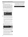
9. If it is OK to transmit the data, click the OK button.
Data transmission will begin. The screen will show a
progress bar to indicate the state of progress.
• While transmission is occurring, never turn off
the power or interrupt communication. If for
some reason the console power supply is turned
off, the memory contents of console 2 will be lost.
In this case you will need to initialize console 2.
• Even if you click the CANCEL button in step 9,
part of the setup data and the current data will be
transmitted, so as long as you are operating the
current scene, the two consoles will operate in
tandem.
However, since the libraries and scene do not
match, performing a store/recall operation may
cause the current scene on the two consoles to
have completely different settings.
When transmission is completed, the X symbol will
disappear from the “DUAL” indication in the CON-
NECTION area at the top of the screen. Now the two
consoles can be used simultaneously.
Hint
• If you power-off the system in this state, console 1
will attempt to initiate communication in Dual
Console mode the next time it is powered-on.
• To cancel Dual Console mode, access the DUAL
CONSOLE screen on console 1 or 2, click the
button in the SYSTEM CONFIGURATION field,
and select SINGLE CONSOLE mode.
If Dual Console mode is established, switching to
Single Console mode will set both console 1 and
console 2 to Single Console mode.
If, after communication is established, communica-
tion with the DIGITAL I/O connector or CONTROL
I/O connector is interrupted, a warning message like
the following will appear in the lower part of the
screen. Please check the appropriate connection.
Sayfa yükleniyor...
Sayfa yükleniyor...
Sayfa yükleniyor...
Sayfa yükleniyor...
Sayfa yükleniyor...
Sayfa yükleniyor...
Sayfa yükleniyor...
Sayfa yükleniyor...
Sayfa yükleniyor...
Sayfa yükleniyor...
Sayfa yükleniyor...
Sayfa yükleniyor...
Sayfa yükleniyor...
Sayfa yükleniyor...
Sayfa yükleniyor...
Sayfa yükleniyor...
Sayfa yükleniyor...
Sayfa yükleniyor...
Sayfa yükleniyor...
Sayfa yükleniyor...
Sayfa yükleniyor...
Sayfa yükleniyor...
Sayfa yükleniyor...
Sayfa yükleniyor...
Sayfa yükleniyor...
Sayfa yükleniyor...
Sayfa yükleniyor...
Sayfa yükleniyor...
Sayfa yükleniyor...
Sayfa yükleniyor...
Sayfa yükleniyor...
Sayfa yükleniyor...
Sayfa yükleniyor...
Sayfa yükleniyor...
Sayfa yükleniyor...
Sayfa yükleniyor...
Sayfa yükleniyor...
Sayfa yükleniyor...
Sayfa yükleniyor...
Sayfa yükleniyor...
Sayfa yükleniyor...
Sayfa yükleniyor...
Sayfa yükleniyor...
Sayfa yükleniyor...
Sayfa yükleniyor...
Sayfa yükleniyor...
Sayfa yükleniyor...
Sayfa yükleniyor...
Sayfa yükleniyor...
Sayfa yükleniyor...
Sayfa yükleniyor...
Sayfa yükleniyor...
Sayfa yükleniyor...
Sayfa yükleniyor...
Sayfa yükleniyor...
Sayfa yükleniyor...
Sayfa yükleniyor...
Sayfa yükleniyor...
Sayfa yükleniyor...
Sayfa yükleniyor...
Sayfa yükleniyor...
Sayfa yükleniyor...
Sayfa yükleniyor...
Sayfa yükleniyor...
Sayfa yükleniyor...
Sayfa yükleniyor...
Sayfa yükleniyor...
Sayfa yükleniyor...
Sayfa yükleniyor...
Sayfa yükleniyor...
Sayfa yükleniyor...
Sayfa yükleniyor...
Sayfa yükleniyor...
Sayfa yükleniyor...
Sayfa yükleniyor...
Sayfa yükleniyor...
Sayfa yükleniyor...
Sayfa yükleniyor...
Sayfa yükleniyor...
Sayfa yükleniyor...
Sayfa yükleniyor...
Sayfa yükleniyor...
Sayfa yükleniyor...
Sayfa yükleniyor...
-
 1
1
-
 2
2
-
 3
3
-
 4
4
-
 5
5
-
 6
6
-
 7
7
-
 8
8
-
 9
9
-
 10
10
-
 11
11
-
 12
12
-
 13
13
-
 14
14
-
 15
15
-
 16
16
-
 17
17
-
 18
18
-
 19
19
-
 20
20
-
 21
21
-
 22
22
-
 23
23
-
 24
24
-
 25
25
-
 26
26
-
 27
27
-
 28
28
-
 29
29
-
 30
30
-
 31
31
-
 32
32
-
 33
33
-
 34
34
-
 35
35
-
 36
36
-
 37
37
-
 38
38
-
 39
39
-
 40
40
-
 41
41
-
 42
42
-
 43
43
-
 44
44
-
 45
45
-
 46
46
-
 47
47
-
 48
48
-
 49
49
-
 50
50
-
 51
51
-
 52
52
-
 53
53
-
 54
54
-
 55
55
-
 56
56
-
 57
57
-
 58
58
-
 59
59
-
 60
60
-
 61
61
-
 62
62
-
 63
63
-
 64
64
-
 65
65
-
 66
66
-
 67
67
-
 68
68
-
 69
69
-
 70
70
-
 71
71
-
 72
72
-
 73
73
-
 74
74
-
 75
75
-
 76
76
-
 77
77
-
 78
78
-
 79
79
-
 80
80
-
 81
81
-
 82
82
-
 83
83
-
 84
84
-
 85
85
-
 86
86
-
 87
87
-
 88
88
-
 89
89
-
 90
90
-
 91
91
-
 92
92
-
 93
93
-
 94
94
-
 95
95
-
 96
96
-
 97
97
-
 98
98
-
 99
99
-
 100
100
-
 101
101
-
 102
102
-
 103
103
-
 104
104


Yamaha PM1D Kullanım kılavuzu
- Kategori
- Ses mikserleri
- Tip
- Kullanım kılavuzu
- Bu kılavuz aynı zamanda aşağıdakiler için de uygundur:
diğer dillerde
- español: Yamaha PM1D Manual de usuario
- français: Yamaha PM1D Manuel utilisateur
- italiano: Yamaha PM1D Manuale utente
- svenska: Yamaha PM1D Användarmanual
- 日本語: Yamaha PM1D ユーザーマニュアル
- čeština: Yamaha PM1D Uživatelský manuál
- polski: Yamaha PM1D Instrukcja obsługi
- Deutsch: Yamaha PM1D Benutzerhandbuch
- português: Yamaha PM1D Manual do usuário
- English: Yamaha PM1D User manual
- dansk: Yamaha PM1D Brugermanual
- русский: Yamaha PM1D Руководство пользователя
- Nederlands: Yamaha PM1D Handleiding
- română: Yamaha PM1D Manual de utilizare