
YAMAHA ELECTRONICS CORPORATION, USA
6660 ORANGETHORPE AVE., BUENA PARK, CALIF. 90620, U.S.A.
YAMAHA CANADA MUSIC LTD.
135 MILNER AVE., SCARBOROUGH, ONTARIO M1S 3R1, CANADA
YAMAHA ELECTRONIK EUROPA G.m.b.H.
SIEMENSSTR. 22-34, 25462 RELLINGEN BEI HAMBURG, GERMANY
YAMAHA ELECTRONIQUE FRANCE S.A.
RUE AMBROISE CROIZAT BP70 CROISSY-BEAUBOURG 77312 MARNE-LA-VALLEE CEDEX02, FRANCE
YAMAHA ELECTRONICS (UK) LTD.
YAMAHA HOUSE, 200 RICKMANSWORTH ROAD WATFORD, HERTS WD18 7GQ, ENGLAND
YAMAHA SCANDINAVIA A.B.
J A WETTERGRENS GATA 1, BOX 30053, 400 43 VÄSTRA FRÖLUNDA, SWEDEN
YAMAHA MUSIC AUSTRALIA PTY, LTD.
17-33 MARKET ST., SOUTH MELBOURNE, 3205 VIC., AUSTRALIA
©
2006 All rights reserved.
RX-V359
Printed in China WG72060
RX-V359
AV Receiver
Ampli-tuner audio-vidéo
OWNER’S MANUAL
MODE D’EMPLOI
BEDIENUNGSANLEITUNG
BRUKSANVISNING
MANUALE DI ISTRUZIONI
MANUAL DE INSTRUCCIONES
BE
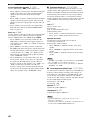
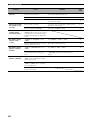
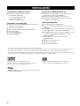
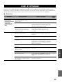
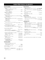
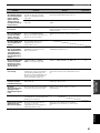
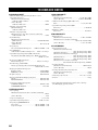
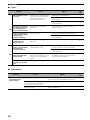
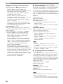
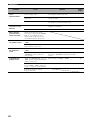
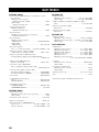
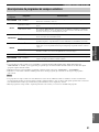
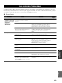
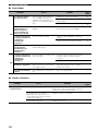
SECCIÓN DE AUDIO
• Potencia de salida RMS mínima para los altavoces delanteros,
central y surround
[Modelos de EE.UU. y Canadá]
1 kHz, THD de 0,9%, 8 Ω/6 Ω ....................................... 110 W
[Otros modelos]
1 kHz, THD de 0,9%, 6 Ω ............................................... 100 W
• Potencia de salida máxima
[Modelo de Europa]
1 kHz, THD de 0,7%, 4 Ω .............................................. 105 W
• Potencia máxima
[Modelos de Asia, China, Corea y general]
1 kHz, THD de 10%, 6 Ω ................................................ 110 W
• Potencia dinámica
[Modelos de EE.UU. y Canadá]
(IHF, 8/6/4/2 Ω) ......................................... 120/140/160/180 W
[Otros modelos]
(IHF, 6/4/2 Ω) .................................................... 105/135/165 W
• Respuesta de frecuencia
CD, etc. a delanteros L/R ....................... 10 Hz a 100 kHz, –3 dB
• Distorsión armónica total
1 kHz, 50 W, 6 Ω, delanteros L/R ........................ 0,06% o menos
• Relación señal a ruido (red IHF-A)
CD (250 mV) a delanteros L/R, efectos apagados
............................................................................... 100 dB o más
• Ruido residual (red IHF-A)
Delanteros L/R .................................................... 150 µV o menos
• Separación de canales (1 kHz/10 kHz)
CD, etc. (5,1 kΩ terminado) a delanteros L/R
...................................................................... 60 dB/45 dB o más
• Control de tono (delanteros L/R)
Refuerzo/corte BASS ............................................ ±10 dB/100 Hz
Refuerzo/corte TREBLE ....................................... ±10 dB/20 kHz
• Salida de auriculares ................................................ 400 mV/470 Ω
• Sensibilidad de entrada/Impedancia de entrada
CD, etc .................................................................. 200 mV/47 kΩ
MULTI CH INPUT ............................................... 200 mV/47 kΩ
• Nivel de salida/Impedancia de salida
AUDIO OUT (REC) ............................................ 200 mV/1,2 kΩ
SUBWOOFER OUTPUT ........................................... 4 V/1,2 kΩ
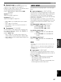
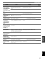
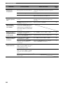
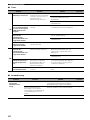
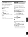
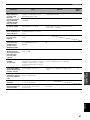
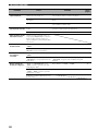
SECCIÓN DE VÍDEO
• Tipo de señal de vídeo
[Modelos de EE.UU., Canadá, Corea y general] ................. NTSC
[Otros modelos] ...................................................................... PAL
• Nivel de señal componente .......................................... 1 Vp-p/75 Ω
• Relación señal a ruido ................................................... 50 dB o más
• Respuesta de frecuencia (MONITOR OUT)
Señal de vídeo ........................................... 5 Hz a 10 MHz, –3 dB
Señal componente ..................................... 5 Hz a 60 MHz, –3 dB
SECCIÓN DE FM
• Gama de sintonización
[Modelos de EE.UU. y Canadá] ....................... 87,5 a 107,9 MHz
[Otros modelos] ............................................ 87,50 a 108,00 MHz
• Umbral de silenciamiento de 50 dB (IHF, mod. del 100%)
Mono ................................................................. 2,8 µV (20,2 dBf)
• Relación señal a ruido (IHF)
Mono/estéreo ............................................................ 73 dB/70 dB
• Distorsión armónica (1 kHz)
Mono/estéreo ............................................................... 0,5%/0,5%
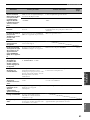
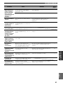
SECCIÓN DE AM
• Gama de sintonización
[Modelos de EE.UU. y Canadá] .......................... 530 a 1710 kHz
[Modelos de Asia y general] ................ 530/531 a 1710/1611 kHz
[Otros modelos] ................................................... 531 a 1611 kHz
GENERALIDADES
• Alimentación
[Modelos de EE.UU. y Canadá] ........................ CA 120 V, 60 Hz
[Modelo de Australia] ........................................ CA 240 V, 50 Hz
[Modelos del R.U. y Europa] ............................ CA 230 V, 50 Hz
[Modelo de Corea] ............................................. CA 220 V, 60 Hz
[Modelo de China] ............................................. CA 220 V, 50 Hz
[Modelos de Asia y general]
............................................. CA 110–120/220–240 V, 50/60 Hz
•Consumo
[Modelos de EE.UU. y Canadá] ............................ 240 W/320 VA
[Otros modelos] .................................................................. 240 W
• Consumo en espera
[Modelos de EE.UU. y Canadá] .......................................... 0,5 W
[Otros modelos] ................................................................... 0,7 W
• Dimensiones (An x Al x Prof) ......................... 435 x 151 x 315 mm
• Peso ......................................................................................... 9,0 kg
* Las especificaciones están sujetas a cambios sin previo aviso.
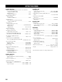
ESPECIFICACIONES
RX-V359_E_cv.fm Page 1 Saturday, January 7, 2006 1:04 PM

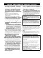
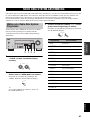
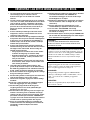
CAUTION: READ THIS BEFORE OPERATING YOUR UNIT.
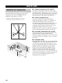
1 To assure the finest performance, please read this
manual carefully. Keep it in a safe place for future
reference.
2 Install this sound system in a well ventilated, cool,
dry, clean place – away from direct sunlight, heat
sources, vibration, dust, moisture, and/or cold.
Allow ventilation space of at least 30 cm on the top,
20 cm on the left and right, and 20 cm on the back of
this unit.
3 Locate this unit away from other electrical
appliances, motors, or transformers to avoid
humming sounds.
4 Do not expose this unit to sudden temperature
changes from cold to hot, and do not locate this unit
in a environment with high humidity (i.e. a room with
a humidifier) to prevent condensation inside this
unit, which may cause an electrical shock, fire,
damage to this unit, and/or personal injury.
5 Avoid installing this unit where foreign object may
fall onto this unit and/or this unit may be exposed to
liquid dripping or splashing. On the top of this unit,
do not place:
– Other components, as they may cause damage
and/or discoloration on the surface of this unit.
– Burning objects (i.e. candles), as they may cause
fire, damage to this unit, and/or personal injury.
– Containers with liquid in them, as they may fall
and liquid may cause electrical shock to the user
and/or damage to this unit.
6 Do not cover this unit with a newspaper, tablecloth,
curtain, etc. in order not to obstruct heat radiation. If
the temperature inside this unit rises, it may cause
fire, damage to this unit, and/or personal injury.
7 Do not plug in this unit to a wall outlet until all
connections are complete.
8 Do not operate this unit upside-down. It may
overheat, possibly causing damage.
9 Do not use force on switches, knobs and/or cords.
10 When disconnecting the power cable from the wall
outlet, grasp the plug; do not pull the cord.
11 Do not clean this unit with chemical solvents; this
might damage the finish. Use a clean, dry cloth.
12 Only voltage specified on this unit must be used.
Using this unit with a higher voltage than specified
is dangerous and may cause fire, damage to this
unit, and/or personal injury. YAMAHA will not be
held responsible for any damage resulting from use
of this unit with a voltage other than specified.
13 To prevent damage by lightning, keep the power
cord and outdoor antennas disconnected from a
wall outlet or the unit during a lightning storm.
14 Do not attempt to modify or fix this unit. Contact
qualified YAMAHA service personnel when any
service is needed. The cabinet should never be
opened for any reasons.
15 When not planning to use this unit for long periods
of time (i.e. vacation), disconnect the AC power plug
from the wall outlet.
16 Install this unit near the AC outlet and where the AC
power plug can be reached easily.
17 Be sure to read the “TROUBLESHOOTING” section
on common operating errors before concluding that
this unit is faulty.
18 Before moving this unit, press STANDBY/ON to set
this unit in the standby mode, and disconnect the
AC power plug from the wall outlet.
■ For U.K. customers
If the socket outlets in the home are not suitable for the
plug supplied with this appliance, it should be cut off and
an appropriate 3 pin plug fitted. For details, refer to the
instructions described below.
The plug severed from the mains lead must be destroyed, as a
plug with bared flexible cord is hazardous if engaged in a live
socket outlet.
■ Special Instructions for U.K. Model
CAUTION: READ THIS BEFORE OPERATING YOUR UNIT.
WARNING
TO REDUCE THE RISK OF FIRE OR ELECTRIC
SHOCK, DO NOT EXPOSE THIS UNIT TO RAIN
OR MOISTURE.
This unit is not disconnected from the AC power
source as long as it is connected to the wall outlet, even
if this unit itself is turned off by STANDBY/ON. This
state is called the standby mode. In this state, this unit
is designed to consume a very small quantity of power.
Note
IMPORTANT
THE WIRES IN MAINS LEAD ARE COLOURED IN
ACCORDANCE WITH THE FOLLOWING CODE:
Blue: NEUTRAL
Brown: LIVE
As the colours of the wires in the mains lead of this
apparatus may not correspond with the coloured
markings identifying the terminals in your plug,
proceed as follows:
The wire which is coloured BLUE must be connected
to the terminal which is marked with the letter N or
coloured BLACK. The wire which is coloured
BROWN must be connected to the terminal which is
marked with the letter L or coloured RED.
Making sure that neither core is connected to the earth
terminal of the three pin plug.

1
PREPARATIONINTRODUCTION
BASIC
OPERATION
ADVANCED
OPERATION
ADDITIONAL
INFORMATION
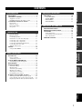
English
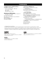
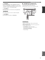
FEATURES............................................................. 2
GETTING STARTED............................................ 3
Supplied accessories .................................................. 3
Installing batteries in the remote control ................... 3
CONTROLS AND FUNCTIONS ......................... 4
Front panel ................................................................. 4
Remote control........................................................... 6
Front panel display .................................................... 8
Rear panel .................................................................. 9
CONNECTIONS .................................................. 10
Placing speakers....................................................... 10
Connecting speakers ................................................ 11
Information on jacks and cable plugs ...................... 13
Connecting video components................................. 14
Connecting audio components................................. 17
Connecting the FM and AM antennas..................... 18
Connecting the power cable..................................... 19
Turning on the power............................................... 19
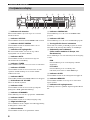
SETUP ................................................................... 20
Using BASIC MENU .............................................. 20
PLAYBACK.......................................................... 23
Basic operations....................................................... 23
Additional operations............................................... 25
SOUND FIELD PROGRAMS............................. 30
Sound field program descriptions............................ 31
RECORDING ....................................................... 34
FM/AM TUNING ................................................. 35
Automatic tuning ..................................................... 35
Manual tuning.......................................................... 36
Automatic preset tuning........................................... 37
Manual preset tuning ............................................... 38
Selecting preset stations........................................... 39
Exchanging preset stations ...................................... 40
RADIO DATA SYSTEM TUNING .................... 41
Selecting the Radio Data System program .............. 41
Using the Radio Data System station network ........ 42
Displaying the Radio Data System information ...... 43
SET MENU ............................................................44
Using SET MENU................................................... 45
SOUND MENU....................................................... 45
INPUT MENU......................................................... 47
OPTION MENU...................................................... 48
TROUBLESHOOTING .......................................49
RESETTING THE SYSTEM...............................53
GLOSSARY...........................................................54
Audio information ................................................... 54
Sound field program information ............................ 55
Video information.................................................... 55
SPECIFICATIONS...............................................56
CONTENTS
INTRODUCTION
PREPARATION
BASIC OPERATION
ADVANCED OPERATION
ADDITIONAL INFORMATION

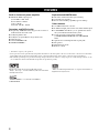
FEATURES
2
Built-in 5-channel power amplifier
◆ Minimum RMS output power
(0.9% THD, 1 kHz, 6 Ω)
Front: 100 W + 100 W
Center: 100 W
Surround: 100 W + 100 W
Decoders and DSP circuits
◆ Proprietary YAMAHA technology for the creation of
multi-channel surround sound
◆ Dolby Digital decoder
◆ Dolby Pro Logic/Dolby Pro Logic II decoder
◆ DTS decoder
◆ Virtual CINEMA DSP
◆ SILENT CINEMA
™
Sophisticated AM/FM tuner
◆ 40-station random and direct preset tuning
◆ Automatic preset tuning
◆ Preset station shifting capability (preset editing)
Other features
◆ 192-kHz/24-bit D/A converter
◆ 6 additional input jacks for discrete multi-channel input
◆ A SET MENU that allows you to optimize this unit to
suit your individual audiovisual system
◆ Component video input/output capability
(3 COMPONENT VIDEO INs and 1 MONITOR
OUT)
◆ Optical and coaxial digital audio signal jacks
◆ Sleep timer
◆ Night listening mode
◆ Remote control
• y indicates a tip for your operation.
• Some operations can be performed by using either the buttons on the front panel or the ones on the remote control. In case the button
names differ between the front panel and the remote control, the button name on the remote control is given in parentheses.
• This manual is printed prior to production. Design and specifications are subject to change in part as a result of improvements, etc. In
case of differences between the manual and product, the product has priority.
Manufactured under license from Dolby Laboratories.
“Dolby”, “Pro Logic”, and the double-D symbol are trademarks
of Dolby Laboratories.
“SILENT CINEMA” is a trademark of YAMAHA
CORPORATION.
“DTS” and “DTS Digital Surround” are registered trademarks of
Digital Theater Systems, Inc.
FEATURES

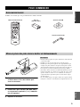
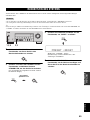
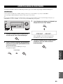
GETTING STARTED
3
INTRODUCTION
English
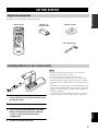
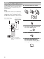
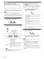
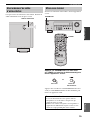
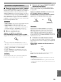
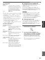
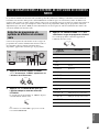
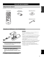
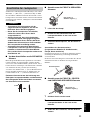
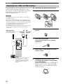
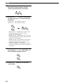
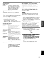
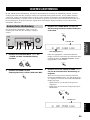
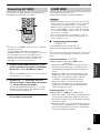
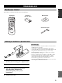
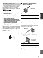
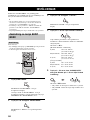
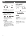
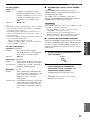
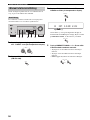
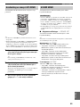
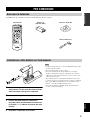
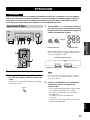
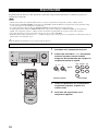
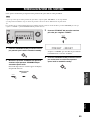
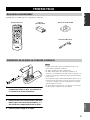
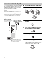
Check that you received all of the following parts.
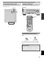
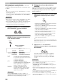
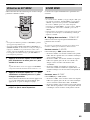
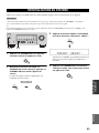
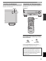
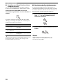
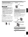
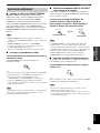
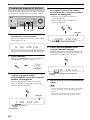
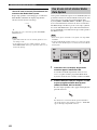
1 Press the tab of the battery compartment
cover and pull it in the direction of the arrow
to open the cover.
2 Remove the cover.
3 Insert the two supplied batteries (AA, R06,
UM-3) according to the polarity markings
(+ and –) on the inside of the battery
compartment.
4 Put the cover back into place.
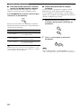
• Change all of the batteries if you notice a decrease in the
operation range of the remote control.
• Do not use an old battery together with a new one.
• Do not use different types of batteries (such as alkaline and
manganese batteries) together. Read the packaging carefully as
these different types of batteries may have the same shape and
color.
• If the batteries have leaked, dispose of them immediately. Avoid
touching the leaked material or letting it come into contact with
clothing, etc. Clean the battery compartment thoroughly before
installing new batteries.
• Do not throw away batteries with general house waste; dispose
of them correctly in accordance with your local regulations.
GETTING STARTED
Supplied accessories
DVD
CD
TUNER
STANDARD
TEST
VOLUME
PROG PROG
SET MENU
LEVEL
VOLUME
MUTE
STRAIGHT
5CH STEREO
NIGHT
SLEEP
A/B/C/D/E
PRESET
MD/CD-R
V-A UX
MULTI CH IN
DTV/CBL
VCR
POWER
Remote control
Batteries (2)
(AA, R06, UM-3)
AM loop antenna
Indoor FM antenna
Installing batteries in the remote control
1
2
4
3
Notes

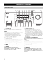
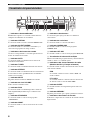
CONTROLS AND FUNCTIONS
4
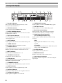
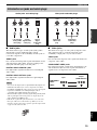
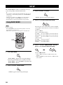
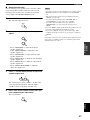
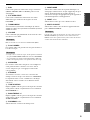
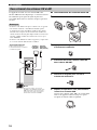
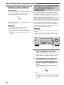
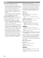
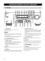
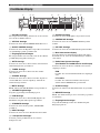
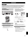
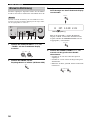
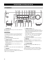
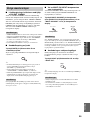
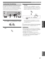
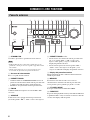
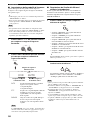
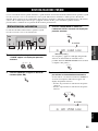
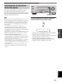
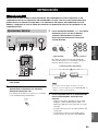
1 STANDBY/ON
Turns on this unit or sets it to the standby mode.
• In the standby mode, this unit consumes a small amount of
power in order to receive infrared-signals from the remote
control.
• When you turn on this unit, there will be a 4 to 5-second delay
before this unit can reproduce sound.
2 Remote control sensor
Receives signals from the remote control.
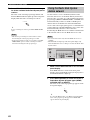
3 PRESET/TUNING
• Switches the function of PRESET/TUNING
l
/
h
between selecting preset station numbers and selecting
the tuning frequency.
• Edits the assignments of present stations.
4 FM/AM
Switches the reception band between FM and AM.
5 A/B/C/D/E
Selects one of the 5 preset station groups (A to E) when
“FM” or “AM” is selected as the input source.
6 PRESET/TUNING l / h
• Selects one of the 8 preset station numbers (1 to 8)
when “FM” or “AM” is selected as the input source.
The colon (:) is displayed in the front panel display.
• Selects the tuning frequency when “FM” or “AM” is
selected as the input source. The colon (:) is not
displayed in the front panel display.
7 Front panel display
Shows information about the operational status of this unit.
8 MEMORY
Stores a preset station in the memory. Hold down this
button for more than 3 seconds to start automatic preset
tuning.
9 PTY SEEK MODE
Sets this unit in the PTY SEEK mode.
0 FREQ/TEXT
Switches the Radio Data System display between the PS
mode, PTY mode, RT mode, CT mode (if the station
offers the corresponding data services) and the frequency
display.
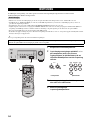
CONTROLS AND FUNCTIONS
Front panel
PHONES
SILENT CINEMA
SPEAKERS
STRAIGHT
PRESET
TUNING
FM
AM
PRESET
MEMORY
TUNING MODE
PTY SEEK
MODE
START
EON
TEXT
FREQ
TUNING
A
B
C
D
E
TONE CONTROL
TREBLE
PROGRAM
INPUT MODE
MULTI CH INPUT
INPUT
BASS
EFFECT
EDIT
NEXT
SET MENU
MAN'L
AUTO F M
STANDBY
ON
A
B
OFF
AUTO
MAN'L
VOLUME
1
EFGH JIKLM
234 5 67890ABC D
Notes

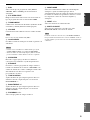
CONTROLS AND FUNCTIONS
5
INTRODUCTION
English
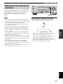
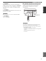
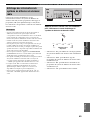
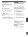
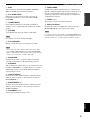
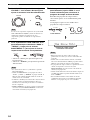
A EON
Selects a radio program type (NEWS, AFFAIRS, INFO,
or SPORT) for automatic tuning.
B PTY SEEK START
Starts searching for a station once the desired program
type is selected in the PTY SEEK mode.
C TUNING MODE
Switches between automatic tuning (the AUTO indicator
is turned on) and manual tuning (the AUTO indicator is
turned off).
D VOLUME
Controls the output level of all audio channels.
This does not affect the AUDIO OUT (REC) level.
E PHONES jack
Outputs audio signals for private listening with
headphones.
• When you connect headphones, no signals are output at the
SUBWOOFER OUTPUT jack or at the SPEAKERS terminals.
• All Dolby Digital and DTS audio signals are mixed down to the
left and right headphone channels.
F SPEAKERS
Turns on or off the set of front speakers connected to the A
and/or B terminals on the rear panel.
G STRAIGHT
Turns the sound field programs off or on. When this unit is
in the “STRAIGHT” mode, 2-channel or multi-channel
input signals are output directly from their respective
speakers without effect processing.
H TONE CONTROL
Adjusts the bass/treble balance of the front left and right
speakers in conjunction with BASS/TREBLE +/–.
I BASS/TREBLE +/–
Adjusts the bass/treble balance of the front left and right
speakers in conjunction with TONE CONTROL.
J PROGRAM l / h
Selects sound field programs.
K INPUT MODE
Selects either digital or analog input signals exclusively or
sets this unit to automatically detect the type of input
signals and select the corresponding input signals when
one component is connected via both digital and analog
connections.
L INPUT l / h
Selects the desired input source.
M MULTI CH INPUT
Selects the component connected to the MULTI CH
INPUT jacks as the input source.
The input source connected to the MULTI CH INPUT jacks takes
priority over the source selected with INPUT l / h on the front
panel (or the input selector buttons on the remote control).
Note
Notes
Note

CONTROLS AND FUNCTIONS
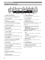
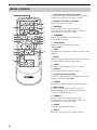
6
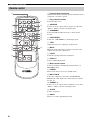
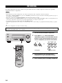
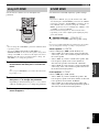
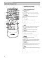
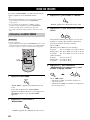
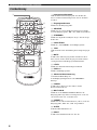
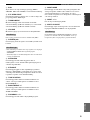
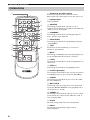
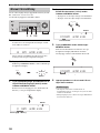
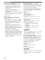
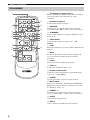
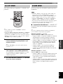
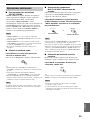
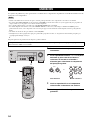
1 Infrared signal transmitter
Outputs infrared control signals. Aim the transmitter at the
component you want to operate.
2 Input selector buttons
Select the input source.
3 A/B/C/D/E
Selects one of the 5 preset station groups (A to E) when
“FM” or “AM” is selected as the input source.
4 STANDARD
Selects the built-in Dolby Pro Logic or Pro Logic II
decoder.
5 5CH STEREO
Selects the “5CH STEREO” sound field program.
6 TEST
Outputs the test tone to adjust the speaker levels.
7 MUTE
Mutes the audio output. Press again to restore the audio
output to the previous volume level.
8 LEVEL
Selects the speaker channel to be adjusted.
9 PROG +/–
Selects sound field programs.
0 Multi control section
Selects and adjusts sound field program parameters or
SET MENU items.
A POWER
Turns on this unit or set it to the standby mode.
B MULTI CH IN
Selects the component connected to the MULTI CH
INPUT jacks as the input source when using an external
decoder, etc.
C PRESET +/–
Selects one of the 8 preset station numbers (1 to 8) when
“FM” or “AM” is selected as the input source.
D SLEEP
Sets the sleep timer.
E NIGHT
Turns on or off the night listening mode.
Remote control
DVD
CD
TUNER
STANDARD
TEST
VOLUME
PROG PROG
SET MENU
LEVEL
VOLUME
MUTE
STRAIGHT
5CH STEREO
NIGHT
SLEEP
A/B/C/D/E
PRESET
MD/CD-R
V-AUX
MULTI CH IN
DTV/CBL
VCR
POWER
1
2
3
6
7
8
9
0
A
B
C
D
E
F
G
H
4
5

CONTROLS AND FUNCTIONS
7
INTRODUCTION
English
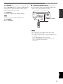
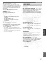
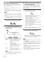
F STRAIGHT
Turns the sound field programs off or on. When this unit is
in the “STRAIGHT” mode, 2-channel or multi-channel
input signals are output directly from their respective
speakers without effect processing.
G VOLUME +/–
Controls the output level of all audio channels.
This does not affect the AUDIO OUT (REC) level.
H SET MENU
Enters “SET MENU”.
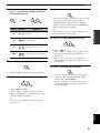
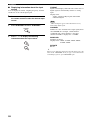
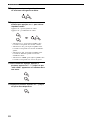
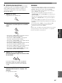
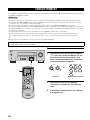
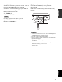
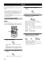
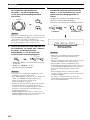
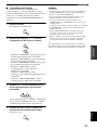
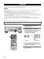
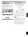
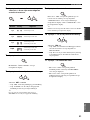
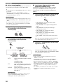
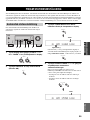
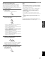
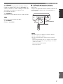
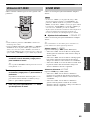
■ Using the remote control
The remote control transmits a directional infrared ray.
Be sure to aim the remote control directly at the remote
control sensor on this unit during operation.
• Do not spill water or other liquids on the remote control.
• Do not drop the remote control.
• Do not leave or store the remote control in the following types
of conditions:
– places of high humidity, such as near a bath
– places of high temperature, such as near a heater or stove
– places of extremely low temperatures
– dusty places
Note
Notes
30º 30º
Approximately 6 m (20 ft)

CONTROLS AND FUNCTIONS
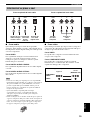
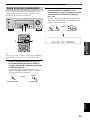
8
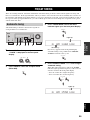
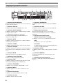
1 Decoder indicators
The respective indicator lights up when any of the
decoders of this unit function.
2 VIRTUAL indicator
Lights up when Virtual CINEMA DSP is active.
3 SILENT CINEMA indicator
Lights up when headphones are connected and a sound
field program is selected.
4 Input source indicators
A corresponding cursor lights up to show the currently
selected input source.
5 AUTO indicator
Lights up when this unit is in the automatic tuning mode.
6 TUNED indicator
Lights up when this unit is tuned into a station.
7 STEREO indicator
Lights up when this unit is receiving a strong signal for an
FM stereo broadcast while the AUTO indicator is lit.
8 MUTE indicator
Flashes while the MUTE function is on.
9 VOLUME level indicator
Indicates the current volume level.
0 PCM indicator
Lights up when this unit is reproducing PCM (Pulse Code
Modulation) digital audio signals.
A STANDARD indicator
Lights up when the “STANDARD” program is selected.
B NIGHT indicator
Lights up when you select a night listening mode.
C Speaker indicators
Light up according to the set of front speakers selected.
D Headphones indicator
Lights up when headphones are connected.
E CINEMA DSP indicator
Lights up when you select a CINEMA DSP program.
F HiFi DSP indicator
Lights up when you select a HiFi DSP program.
G Multi-information display
Shows the name of the current program and other
information when adjusting or changing settings.
H Radio Data System indicators
(U.K. and Europe models only)
Lights up when the Radio Data System data is being
received.
EON
Lights up when the EON data service is being
received.
PTY HOLD
Lights up while searching for the Radio Data System
stations in the PTY SEEK mode.
I SLEEP indicator
Lights up while the sleep timer is on.
J MEMORY indicator
Flashes to show that a station can be stored.
K Input channel indicators
Indicate the channel components of the current digital
input signal.
Front panel display
VIRTUAL
SILENT CINEMA
STANDARD NIGHT
AB
SP
HiFi DSP
AUTO
TUNED
STEREO
MEMORY
MUTE
VOLUME
PTY
HOLD PS
PTY
RT
CT EON
SLEEP
ft
dB
LFE SL SR
L
C
R
dB
VCR
V-AUX
DTV/CBL
DVD
MD/CD-R
TUNER CD
DIGITAL
PCM
PL
PL
G
0ABCEDF JIK
H
1 32 4 756 8 9

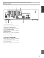
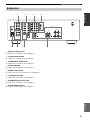
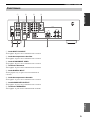
CONTROLS AND FUNCTIONS
9
INTRODUCTION
English
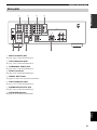
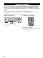
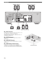
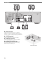
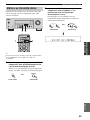
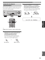
1 MULTI CH INPUT jacks
See page 16 for connection information.
2 Video component jacks
See page 14 for connection information.
3 COMPONENT VIDEO jacks
See page 16 for connection information.
4 Antenna terminals
See page 18 for connection information.
5 DIGITAL INPUT jacks
See pages 14 and 15 for connection information.
6 Audio component jacks
See page 17 for connection information.
7 SUBWOOFER OUTPUT jack
See page 12 for connection information.
8 SPEAKERS terminals
See page 11 for connection information.
Rear panel
MULTI CH INPUT
FRONT
CENTER
SUB
WOOFER
SURROUND
CD
MD/
CD-R
(PLAY)
(REC)
IN
OUT
L
R
DIGITAL
INPUT
DVD
COAXIAL
3
DTV/CBL
OPTICAL
DVD
AUDIO
AUDIO
L
R
DVD
DTV/
CBL
IN
OUT
VCR
VCR
V-AUX
VIDEO
OUTPUT
SUB
WOOFER
MONITOR
OUT
DTV/
CBL
DV
D
A
B
C
COMPONENT VIDEO
PBYPR
MONITOR OUT
SURROUND
L
R
AM
ANT
GND
FM
ANT
TUNER
2
1
SPEAKERS
L
R
B
A
FRONT
CENTER
FRON
T
L
R
1234
56 7 8

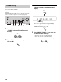
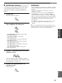
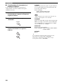
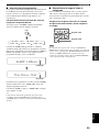
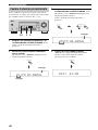
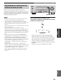
CONNECTIONS
10
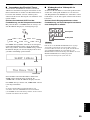
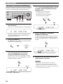
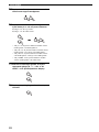
The speaker layout below shows the standard ITU-R
*
speaker setting. You can use it to enjoy CINEMA DSP and
multi-channel audio sources.
*
ITU-R is the radio communication sector of the ITU
(International Telecommunication Union).
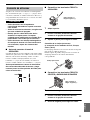
■ Front speakers (FL and FR)
The front speakers are used for the main source sound plus
effect sounds. Place these speakers an equal distance from
the ideal listening position. The distance of each speaker
from each side of the video monitor should be the same.
■ Center speaker (C)
The center speaker is for the center channel sounds
(dialog, vocals, etc.). If for some reason it is not practical
to use a center speaker, you can do without it. Best results,
however, are obtained with the full system. Place the
center speaker centrally between the front speakers and as
close to the monitor as possible, such as directly over or
under it.
■ Surround speakers (SL and SR)
The surround speakers are used for effect and surround
sounds. Place these speakers behind your listening
position, facing slightly inwards, about 1.8 m (6 ft) above
the floor.
■ Subwoofer (SW)
The use of a subwoofer, such as the YAMAHA Active
Servo Processing Subwoofer System, is effective not only
for reinforcing bass frequencies from any or all channels,
but also for high fidelity reproduction of the LFE (low-
frequency effect) channel included in Dolby Digital and
DTS software. The position of the subwoofer is not so
critical, because low bass sounds are not highly
directional. But it is better to place the subwoofer near the
front speakers. Turn it slightly toward the center of the
room to reduce wall reflections.
CONNECTIONS
Placing speakers
60˚
30˚
FL
FR
C
SL
SR
SR
80˚
SL
FR
FL
C
SL
SR
SW
1.8 m (6 ft)

11
CONNECTIONS
PREPARATION
English
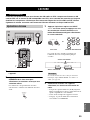
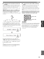
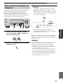
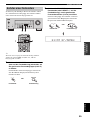
Be sure to connect the left channel (L), right channel (R),
“+” (red) and “–” (black) properly. If the connections are
faulty, no sound will be heard from the speakers, and if the
polarity of the speaker connections is incorrect, the sound
will be unnatural and lack bass.
• Use speakers with the specified impedance
shown on the rear panel of this unit.
• Before connecting the speakers, make sure
that this unit is turned off.
• Do not let the bare speaker wires touch each
other or do not let them touch any metal part
of this unit. This could damage this unit and/or
speakers.
• Use magnetically shielded speakers. If this
type of speakers still creates the interference
with the monitor, place the speakers away
from the monitor.
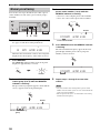
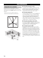
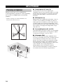
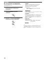
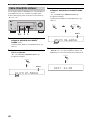
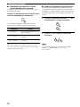
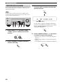
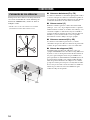
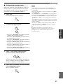
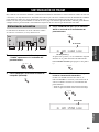
■ Before connecting to the SPEAKERS
terminal
A speaker cord is actually a pair of insulated cables
running side by side. Cables are colored or shaped
differently, perhaps with a stripe, groove or ridges.
Connect the striped (grooved, etc.) cable to the “+” (red)
terminals of this unit and your speaker. Connect the plain
cable to the “–” (black) terminals.
Remove approximately 10 mm (3/8”) of insulation
from the end of each speaker cable and then
twist the bare wires of the cable together to
prevent short circuits.
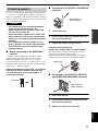
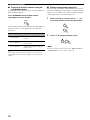
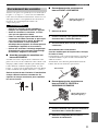
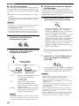
■ Connecting to the FRONT A SPEAKERS
terminals
1 Loosen the knob.
2 Insert the bare end of the speaker wire into
the hole on the terminal.
3 Tighten the knob to secure the wire.
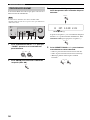
Connecting the banana plug
(except U.K., Europe, Korea and Asia models)
The banana plug is a single-pole electrical connector
widely used to terminate speaker cables.
First, tighten the knob and then insert the banana plug
connector into the end of the corresponding terminal.
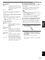
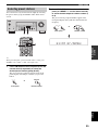
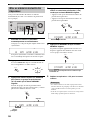
■ Connecting to the FRONT B, CENTER,
and SURROUND SPEAKERS terminals
1 Press down the tab.
2 Insert the bare end of the speaker wire into
the hole on the terminal.
3 Release the tab to secure the wire.
Connecting speakers
CAUTION
10 mm (3/8”)
1
2
3
Red: positive (+)
Black: negative (–)
Banana plug
3
1
2
Red: positive (+)
Black: negative (–)

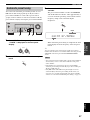
12
CONNECTIONS
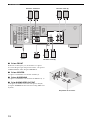
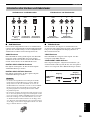
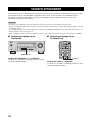
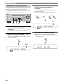
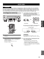
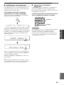
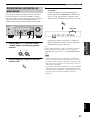
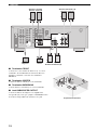
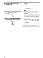
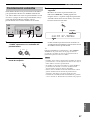
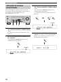
■ FRONT terminals
Connect one or two speaker systems (1, 2) to these
terminals. If you use only one front speaker system,
connect it to the FRONT A terminals.
■ CENTER terminals
Connect a center speaker (3) to these terminals.
■ SURROUND terminals
Connect surround speakers (4, 5) to these terminals.
■ SUBWOOFER OUTPUT jack
Connect a subwoofer with built-in amplifier (6) (such as
the YAMAHA Active Servo Processing Subwoofer
System) to this jack.
MULTI CH INPUT
FRONT
CENTER
SUB
WOOFER
SURROUND
CD
MD/
CD-R
(PLAY)
(REC)
IN
OUT
L
R
DIGITAL
INPUT
DVD
COAXIA
L
3
DTV-CBL
OPTICAL
DVD
AUDIO
AUDIO
L
R
DVD
DTV/
CBL
IN
OUT
VCR
VCR
V-AUX
VIDEO
OUTPUT
SUB
WOOFER
MONITOR
OUT
DTV/
CBL
DV
D
A
B
C
COMPONENT VIDEO
PBYPR
MONITOR OUT
SURROUND
L
R
AM
ANT
GND
FM
ANT
TUNER
2
1
SPEAKERS
L
R
B
A
FRONT
CENTER
FRON
T
L
R
5
31 2
2
4
1
6
Subwoofer Center
speaker
Front speakers (A)
LeftRight
Surround speakers
Front speakers (B)
LeftRight
LeftRight
6
1
2
5
4
3
Speaker layout

13
CONNECTIONS
PREPARATION
English
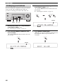
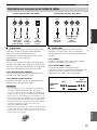
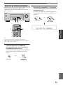
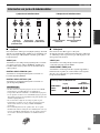
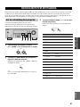
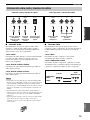
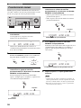
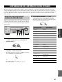
■ Audio jacks
This unit has three types of audio jacks (analog audio,
digital audio coaxial, and digital audio optical).
Connection depends on the availability of audio jacks on
your other components.
AUDIO jacks
For conventional analog audio signals transmitted via left
and right analog audio cables. Connect red plugs to the
right jacks and white plugs to the left jacks.
DIGITAL AUDIO COAXIAL jacks
For digital audio signals transmitted via coaxial digital
audio cables.
DIGITAL AUDIO OPTICAL jacks
For digital audio signals transmitted via optical digital
audio cables.
• You can use the digital jacks to input PCM, Dolby Digital and
DTS bitstreams. When you connect components to both the
COAXIAL and OPTICAL jacks, priority is given to the signals
input at the COAXIAL jack. All digital input jacks are
compatible with 96 kHz sampling digital signals.
• This unit handles digital and analog signals independently. Thus
audio signals input at the analog jacks are output only at the
analog AUDIO OUT (REC) jacks.
• Pull out the cap from the optical jack before you connect the
fiber optic cable. Do not discard the cap. When you are not
using the optical jack, be sure to put the cap back in place. This
cap protects the jack from dust.
■ Video jacks
This unit has two types of video jacks (composite video,
and component video). Connection depends on the
availability of input jacks on your video monitor.
VIDEO jacks
For conventional composite video signals transmitted via
composite video cables.
COMPONENT VIDEO jacks
For component signals, separated into the luminance (Y)
and chrominance (P
B, PR) video signals transmitted on
separate wires of component video cables.
Information on jacks and cable plugs
VIDEO
COMPONENT VIDEO
Y PB PR
PB
Y
P
R
V
COAXIAL
DIGITAL AUDIO
AUDIO
OPTICAL
DIGITAL AUDIO
R
L
C
O
R
L
Left and right
analog audio
cable plugs
Optical
digital
audio cable
plug
Coaxial
digital audio
cable plug
Composite
video cable
plug
Component
video cable
plugs
Audio jacks and cable plugs Video jacks and cable plugs
(Red)(White) (Orange) (Yellow) (Green) (Blue) (Red)
Notes
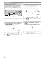
Video signal flow for MONITOR OUT
Output
(MONITOR OUT)
Input
COMPONENT
VIDEO
VIDEO

14
CONNECTIONS
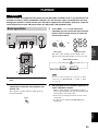
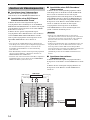
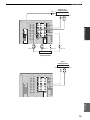
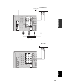
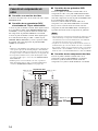
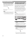
■ Connecting a video monitor
Connect the video input jack of your video monitor to the
MONITOR OUT jack.
■ Connecting a DVD player/cable TV/
satellite tuner
Connect the coaxial digital audio signal output jack of
your DVD player to the DIGITAL INPUT DVD
COAXIAL jack and connect the video signal output jack
of the component to the DVD VIDEO jack of this unit.
Connect the optical digital audio signal output jack of
your cable TV or satellite tuner to the DIGITAL INPUT
DTV/CBL jack and connect the video signal output jack
of the component to the DTV/CBL VIDEO jack of this
unit.
y
• Use the AUDIO jacks of this unit for a video component which
does not have optical digital output jack. To enjoy the surround
sound, use the sound field program selector buttons on the
remote control (see page 30).
• If your DVD player does not have a coaxial digital output jack
but has an optical cable, connect the jack to the DIGITAL
INPUT DVD OPTICAL.
• You can also connect a video monitor, DVD player, digital TV,
and cable TV to this unit using the COMPONENT VIDEO
connections (see page 16).
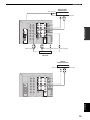
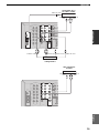
■ Connecting a DVD recorder/VCR
Connect the audio signal input jacks of your video
component to the VCR AUDIO OUT jacks of this unit.
Then connect the video signal input jack of the video
component to the VCR VIDEO OUT jack of this unit for
picture recording.
Connect the audio signal output jacks of your component to
the VCR AUDIO IN jacks of this unit. Then connect the
video signal output jack of the component to the VCR
VIDEO IN jack of this unit to play a source from your
recording component.
• Once you have connected a recording component to this unit,
keep the component turned on while using this unit. If the
power is turned off, this unit may distort the sound from other
components.
• Be sure to connect your video source components in the same
way you connect your video monitor to this unit. For example,
if you connect your video monitor to this unit using a VIDEO
connection, connect your video source components to this unit
using the VIDEO connections.
■ Connecting another video component
Connect the video signal output jack of your component to
the V-AUX VIDEO jack of this unit.
Connect the audio signal output jacks of the component to
the V-AUX AUDIO jacks of this unit.
Connecting video components
Notes
MULTI CH INPUT
FRONT
CENTER
SUB
WOOFER
SURROUND
CD
MD/
CD-R
(PLAY)
(REC)
IN
OUT
L
R
DIGITAL
INPUT
DVD
COAXIA
L
3
DTV/CBL
OPTICAL
DVD
AUDIO
AUDIO
L
R
DVD
DTV/
CBL
IN
OUT
VCR
VCR
V-AUX
VIDEO
OUTPUT
SUB
WOOFER
MONITOR
OUT
DTV/
CBL
DV
D
A
B
C
COMPONEN
PY
MONITOR OUT
SUR
R
R
2
1
VC
L R
V
O
DVD player
Video monitor
Video in
Audio out
Video out
Audio
out
Audio
out

15
CONNECTIONS
PREPARATION
English
MULTI CH INPUT
FRONT
CENTER
SUB
WOOFER
SURROUND
CD
MD/
CD-R
(PLAY)
(REC)
IN
OUT
L
R
DIGITAL
INPUT
DVD
COAXIA
L
3
DTV/CBL
OPTICAL
DVD
AUDIO
AUDIO
L
R
DVD
DTV/
CBL
IN
OUT
VCR
VCR
V-AUX
VIDEO
OUTPUT
SUB
WOOFER
MONITOR
OUT
DTV/
CBL
DV
D
A
B
C
COMPONEN
PY
MONITOR OUT
SUR
R
R
2
1
O
V
L R
VV
LR LR
Cable TV or
Satellite tuner
DVD recorder or
VCR
Audio
out
Audio inAudio out Video outVideo in
Video
out
Audio out
MULTI CH INPUT
FRONT
CENTER
SUB
WOOFER
SURROUND
CD
MD/
CD-R
(PLAY)
(REC)
IN
OUT
L
R
DIGITAL
INPUT
DVD
COAXIA
L
3
DTV/CBL
OPTICAL
DVD
AUDIO
AUDIO
L
R
DVD
DTV/
CBL
IN
OUT
VCR
VCR
V-AUX
VIDEO
OUTPUT
SUB
WOOFER
MONITOR
OUT
DTV/
CBL
DV
D
A
B
C
COMPONEN
PY
MONITOR OUT
SUR
R
R
2
1
L R
V
Another video
component
Audio
out
Video
out

16
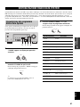
CONNECTIONS
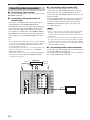
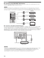
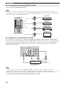
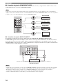
■ Connecting to the COMPONENT VIDEO jacks
You can enjoy high-quality pictures by connecting your video monitor and video source components to this unit using
COMPONENT VIDEO connections.
Be sure to connect your video source components in the same way you connect your video monitor to this unit. For example, if you
connect your video monitor to this unit using a COMPONENT VIDEO connection, connect your video source components to this unit
using the COMPONENT VIDEO connection.
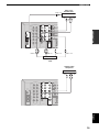
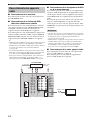
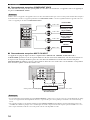
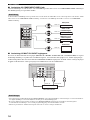
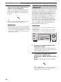
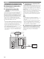
■ Connecting to the MULTI CH INPUT jacks
This unit is equipped with 6 additional input jacks (FRONT L/R, CENTER, SURROUND L/R and SUBWOOFER) for
discrete multi-channel input from a multi-format player, external decoder or sound processor. Connect the output jacks
on your multi-format player or external decoder to the MULTI CH INPUT jacks. Be sure to match the left and right
output jacks to the left and right input jacks for the front and surround channels.
• When you select the component connected to the MULTI CH INPUT jacks as the input source (see page 25), this unit automatically
turns off the digital sound field processor, and you cannot select sound field programs.
• This unit does not redirect signals input at the MULTI CH INPUT jacks to accommodate for missing speakers. We recommend that
you connect a 5.1-channel speaker system before using this feature.
• When headphones are used, signals are output only from the front left and right channels.
Note
Notes
VCR
DTV/
CBL
DV
D
A
B
C
COMPONENT VIDEO
PBYPR
MONITOR OUT
SURROUND
L
R
PR
PB
Y
PR
PB
Y
PR
PB
Y
PB
PR
Y
Video monitor
DVD player
DVD recorder or
VCR
Video out
Video out
Video out
Video in
Cable TV or
satellite tuner
MULTI CH INPUT
FRONT
CENTER
SUB
WOOFER
SURROUND
CD
DIGITAL
INPUT
DVD
COAXIAL
3
AUDIO
L
R
DVD
DTV/
CBL
IN
V-AUX
VID
E
LR
LR
Multi-format player or
external decoder
Surround outCenter out
Subwoofer out Front out

17
CONNECTIONS
PREPARATION
English
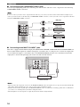
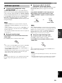
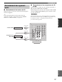
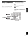
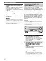
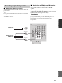
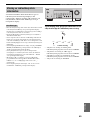
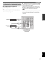
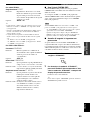
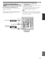
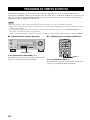
■ Connecting a CD player
Connect the output jacks of your CD player to the CD
jacks of this unit.
y
To make a digital connection to a CD player, select the
corresponding setting for DIGITAL INPUT jacks in “INPUT
ASSIGN” (see page 47).
■ Connecting a CD recorder/MD recorder
Connect the input jacks of your CD recorder or MD
recorder to the MD/CD-R OUT (REC) jacks.
Connect the output jacks of your CD recorder or MD
recorder to the MD/CD-R IN (PLAY) jacks to play a
source from your recording component.
Once you have connected a recording component to this unit,
keep the component turned on while using this unit. If the
component is turned off, this unit may distort the sound from
other components.
Connecting audio components
Note
MULTI CH INPUT
FRONT
CENTER
SUB
WOOFER
SURROUND
CD
MD/
CD-R
(PLAY)
(REC)
IN
OUT
L
R
DIGITAL
INPUT
DVD
COAXIA
L
3
DTV-CBL
OPTICAL
DVD
AUDIO
AUDIO
L
R
DVD
DTV
/
CBL
IN
OU
T
VCR
V-AU
X
OUTPUT
SUB
WOOFER
2
1
L
R
L
R
L
R
CD player
CD recorder or
MD recorder
Audio out
Audio out
Audio in

18
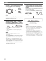
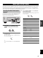
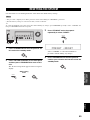
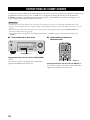
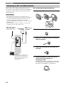
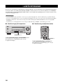
CONNECTIONS
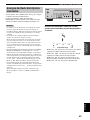
Both FM and AM indoor antennas are supplied with this
unit. In general, these antennas should provide sufficient
signal strength. Connect each antenna correctly to the
designated terminals.
• The AM loop antenna should be placed away from this unit.
• A properly installed outdoor antenna provides clearer reception
than an indoor one. If you experience poor reception quality,
install an outdoor antenna. Consult the nearest authorized
YAMAHA dealer or service center about outdoor antennas.
• The AM loop antenna should always be connected, even if an
outdoor AM antenna is connected to this unit.
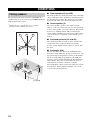
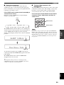
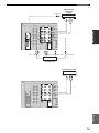
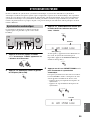
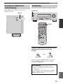
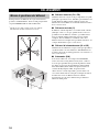
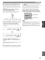
■ Connecting the AM loop antenna
1 Set up the AM loop antenna.
2 Press down the tab of the AM ANT terminal.
3 Insert the one of the AM loop antenna lead
wires into the AM ANT terminal.
4 Release the tab back to secure the wire.
5 Repeat steps 2 through 4 to connect the
other lead wire to the GND terminal.
Once you have properly connected the AM loop
antenna to this unit, orient the AM loop antenna for
the best reception when you tune into AM stations.
Connecting the FM and AM antennas
Notes
AM
ANT
GND
FM
ANT
TUNER
AM loop
antenna
(supplied)
Ground
For maximum safety and minimum
interference, connect the antenna GND
terminal to a good earth ground. A good
earth ground is a metal stake driven into
moist earth.
Indoor FM
antenna
(supplied)
Outdoor AM antenna
Use a 5 to 10 m (16 to 32 ft) of
vinyl-covered wire extended
outdoors from a window.
Sayfa yükleniyor...
Sayfa yükleniyor...
Sayfa yükleniyor...
Sayfa yükleniyor...
Sayfa yükleniyor...
Sayfa yükleniyor...
Sayfa yükleniyor...
Sayfa yükleniyor...
Sayfa yükleniyor...
Sayfa yükleniyor...
Sayfa yükleniyor...
Sayfa yükleniyor...
Sayfa yükleniyor...
Sayfa yükleniyor...
Sayfa yükleniyor...
Sayfa yükleniyor...
Sayfa yükleniyor...
Sayfa yükleniyor...
Sayfa yükleniyor...
Sayfa yükleniyor...
Sayfa yükleniyor...
Sayfa yükleniyor...
Sayfa yükleniyor...
Sayfa yükleniyor...
Sayfa yükleniyor...
Sayfa yükleniyor...
Sayfa yükleniyor...
Sayfa yükleniyor...
Sayfa yükleniyor...
Sayfa yükleniyor...
Sayfa yükleniyor...
Sayfa yükleniyor...
Sayfa yükleniyor...
Sayfa yükleniyor...
Sayfa yükleniyor...
Sayfa yükleniyor...
Sayfa yükleniyor...
Sayfa yükleniyor...
Sayfa yükleniyor...
Sayfa yükleniyor...
Sayfa yükleniyor...
Sayfa yükleniyor...
Sayfa yükleniyor...
Sayfa yükleniyor...
Sayfa yükleniyor...
Sayfa yükleniyor...
Sayfa yükleniyor...
Sayfa yükleniyor...
Sayfa yükleniyor...
Sayfa yükleniyor...
Sayfa yükleniyor...
Sayfa yükleniyor...
Sayfa yükleniyor...
Sayfa yükleniyor...
Sayfa yükleniyor...
Sayfa yükleniyor...
Sayfa yükleniyor...
Sayfa yükleniyor...
Sayfa yükleniyor...
Sayfa yükleniyor...
Sayfa yükleniyor...
Sayfa yükleniyor...
Sayfa yükleniyor...
Sayfa yükleniyor...
Sayfa yükleniyor...
Sayfa yükleniyor...
Sayfa yükleniyor...
Sayfa yükleniyor...
Sayfa yükleniyor...
Sayfa yükleniyor...
Sayfa yükleniyor...
Sayfa yükleniyor...
Sayfa yükleniyor...
Sayfa yükleniyor...
Sayfa yükleniyor...
Sayfa yükleniyor...
Sayfa yükleniyor...
Sayfa yükleniyor...
Sayfa yükleniyor...
Sayfa yükleniyor...
Sayfa yükleniyor...
Sayfa yükleniyor...
Sayfa yükleniyor...
Sayfa yükleniyor...
Sayfa yükleniyor...
Sayfa yükleniyor...
Sayfa yükleniyor...
Sayfa yükleniyor...
Sayfa yükleniyor...
Sayfa yükleniyor...
Sayfa yükleniyor...
Sayfa yükleniyor...
Sayfa yükleniyor...
Sayfa yükleniyor...
Sayfa yükleniyor...
Sayfa yükleniyor...
Sayfa yükleniyor...
Sayfa yükleniyor...
Sayfa yükleniyor...
Sayfa yükleniyor...
Sayfa yükleniyor...
Sayfa yükleniyor...
Sayfa yükleniyor...
Sayfa yükleniyor...
Sayfa yükleniyor...
Sayfa yükleniyor...
Sayfa yükleniyor...
Sayfa yükleniyor...
Sayfa yükleniyor...
Sayfa yükleniyor...
Sayfa yükleniyor...
Sayfa yükleniyor...
Sayfa yükleniyor...
Sayfa yükleniyor...
Sayfa yükleniyor...
Sayfa yükleniyor...
Sayfa yükleniyor...
Sayfa yükleniyor...
Sayfa yükleniyor...
Sayfa yükleniyor...
Sayfa yükleniyor...
Sayfa yükleniyor...
Sayfa yükleniyor...
Sayfa yükleniyor...
Sayfa yükleniyor...
Sayfa yükleniyor...
Sayfa yükleniyor...
Sayfa yükleniyor...
Sayfa yükleniyor...
Sayfa yükleniyor...
Sayfa yükleniyor...
Sayfa yükleniyor...
Sayfa yükleniyor...
Sayfa yükleniyor...
Sayfa yükleniyor...
Sayfa yükleniyor...
Sayfa yükleniyor...
Sayfa yükleniyor...
Sayfa yükleniyor...
Sayfa yükleniyor...
Sayfa yükleniyor...
Sayfa yükleniyor...
Sayfa yükleniyor...
Sayfa yükleniyor...
Sayfa yükleniyor...
Sayfa yükleniyor...
Sayfa yükleniyor...
Sayfa yükleniyor...
Sayfa yükleniyor...
Sayfa yükleniyor...
Sayfa yükleniyor...
Sayfa yükleniyor...
Sayfa yükleniyor...
Sayfa yükleniyor...
Sayfa yükleniyor...
Sayfa yükleniyor...
Sayfa yükleniyor...
Sayfa yükleniyor...
Sayfa yükleniyor...
Sayfa yükleniyor...
Sayfa yükleniyor...
Sayfa yükleniyor...
Sayfa yükleniyor...
Sayfa yükleniyor...
Sayfa yükleniyor...
Sayfa yükleniyor...
Sayfa yükleniyor...
Sayfa yükleniyor...
Sayfa yükleniyor...
Sayfa yükleniyor...
Sayfa yükleniyor...
Sayfa yükleniyor...
Sayfa yükleniyor...
Sayfa yükleniyor...
Sayfa yükleniyor...
Sayfa yükleniyor...
Sayfa yükleniyor...
Sayfa yükleniyor...
Sayfa yükleniyor...
Sayfa yükleniyor...
Sayfa yükleniyor...
Sayfa yükleniyor...
Sayfa yükleniyor...
Sayfa yükleniyor...
Sayfa yükleniyor...
Sayfa yükleniyor...
Sayfa yükleniyor...
Sayfa yükleniyor...
Sayfa yükleniyor...
Sayfa yükleniyor...
Sayfa yükleniyor...
Sayfa yükleniyor...
Sayfa yükleniyor...
Sayfa yükleniyor...
Sayfa yükleniyor...
Sayfa yükleniyor...
Sayfa yükleniyor...
Sayfa yükleniyor...
Sayfa yükleniyor...
Sayfa yükleniyor...
Sayfa yükleniyor...
Sayfa yükleniyor...
Sayfa yükleniyor...
Sayfa yükleniyor...
Sayfa yükleniyor...
Sayfa yükleniyor...
Sayfa yükleniyor...
Sayfa yükleniyor...
Sayfa yükleniyor...
Sayfa yükleniyor...
Sayfa yükleniyor...
Sayfa yükleniyor...
Sayfa yükleniyor...
Sayfa yükleniyor...
Sayfa yükleniyor...
Sayfa yükleniyor...
Sayfa yükleniyor...
Sayfa yükleniyor...
Sayfa yükleniyor...
Sayfa yükleniyor...
Sayfa yükleniyor...
Sayfa yükleniyor...
Sayfa yükleniyor...
Sayfa yükleniyor...
Sayfa yükleniyor...
Sayfa yükleniyor...
Sayfa yükleniyor...
Sayfa yükleniyor...
Sayfa yükleniyor...
Sayfa yükleniyor...
Sayfa yükleniyor...
Sayfa yükleniyor...
Sayfa yükleniyor...
Sayfa yükleniyor...
Sayfa yükleniyor...
Sayfa yükleniyor...
Sayfa yükleniyor...
Sayfa yükleniyor...
Sayfa yükleniyor...
Sayfa yükleniyor...
Sayfa yükleniyor...
Sayfa yükleniyor...
Sayfa yükleniyor...
Sayfa yükleniyor...
Sayfa yükleniyor...
Sayfa yükleniyor...
Sayfa yükleniyor...
Sayfa yükleniyor...
Sayfa yükleniyor...
Sayfa yükleniyor...
Sayfa yükleniyor...
Sayfa yükleniyor...
Sayfa yükleniyor...
Sayfa yükleniyor...
Sayfa yükleniyor...
Sayfa yükleniyor...
Sayfa yükleniyor...
Sayfa yükleniyor...
Sayfa yükleniyor...
Sayfa yükleniyor...
Sayfa yükleniyor...
Sayfa yükleniyor...
Sayfa yükleniyor...
Sayfa yükleniyor...
Sayfa yükleniyor...
Sayfa yükleniyor...
Sayfa yükleniyor...
Sayfa yükleniyor...
Sayfa yükleniyor...
Sayfa yükleniyor...
Sayfa yükleniyor...
Sayfa yükleniyor...
Sayfa yükleniyor...
Sayfa yükleniyor...
Sayfa yükleniyor...
Sayfa yükleniyor...
Sayfa yükleniyor...
Sayfa yükleniyor...
Sayfa yükleniyor...
Sayfa yükleniyor...
Sayfa yükleniyor...
Sayfa yükleniyor...
Sayfa yükleniyor...
Sayfa yükleniyor...
Sayfa yükleniyor...
Sayfa yükleniyor...
Sayfa yükleniyor...
Sayfa yükleniyor...
Sayfa yükleniyor...
Sayfa yükleniyor...
Sayfa yükleniyor...
Sayfa yükleniyor...
Sayfa yükleniyor...
Sayfa yükleniyor...
Sayfa yükleniyor...
Sayfa yükleniyor...
Sayfa yükleniyor...
Sayfa yükleniyor...
Sayfa yükleniyor...
Sayfa yükleniyor...
Sayfa yükleniyor...
Sayfa yükleniyor...
Sayfa yükleniyor...
Sayfa yükleniyor...
Sayfa yükleniyor...
Sayfa yükleniyor...
Sayfa yükleniyor...
Sayfa yükleniyor...
Sayfa yükleniyor...
Sayfa yükleniyor...
Sayfa yükleniyor...
Sayfa yükleniyor...
Sayfa yükleniyor...
Sayfa yükleniyor...
Sayfa yükleniyor...
Sayfa yükleniyor...
Sayfa yükleniyor...
Sayfa yükleniyor...
-
 1
1
-
 2
2
-
 3
3
-
 4
4
-
 5
5
-
 6
6
-
 7
7
-
 8
8
-
 9
9
-
 10
10
-
 11
11
-
 12
12
-
 13
13
-
 14
14
-
 15
15
-
 16
16
-
 17
17
-
 18
18
-
 19
19
-
 20
20
-
 21
21
-
 22
22
-
 23
23
-
 24
24
-
 25
25
-
 26
26
-
 27
27
-
 28
28
-
 29
29
-
 30
30
-
 31
31
-
 32
32
-
 33
33
-
 34
34
-
 35
35
-
 36
36
-
 37
37
-
 38
38
-
 39
39
-
 40
40
-
 41
41
-
 42
42
-
 43
43
-
 44
44
-
 45
45
-
 46
46
-
 47
47
-
 48
48
-
 49
49
-
 50
50
-
 51
51
-
 52
52
-
 53
53
-
 54
54
-
 55
55
-
 56
56
-
 57
57
-
 58
58
-
 59
59
-
 60
60
-
 61
61
-
 62
62
-
 63
63
-
 64
64
-
 65
65
-
 66
66
-
 67
67
-
 68
68
-
 69
69
-
 70
70
-
 71
71
-
 72
72
-
 73
73
-
 74
74
-
 75
75
-
 76
76
-
 77
77
-
 78
78
-
 79
79
-
 80
80
-
 81
81
-
 82
82
-
 83
83
-
 84
84
-
 85
85
-
 86
86
-
 87
87
-
 88
88
-
 89
89
-
 90
90
-
 91
91
-
 92
92
-
 93
93
-
 94
94
-
 95
95
-
 96
96
-
 97
97
-
 98
98
-
 99
99
-
 100
100
-
 101
101
-
 102
102
-
 103
103
-
 104
104
-
 105
105
-
 106
106
-
 107
107
-
 108
108
-
 109
109
-
 110
110
-
 111
111
-
 112
112
-
 113
113
-
 114
114
-
 115
115
-
 116
116
-
 117
117
-
 118
118
-
 119
119
-
 120
120
-
 121
121
-
 122
122
-
 123
123
-
 124
124
-
 125
125
-
 126
126
-
 127
127
-
 128
128
-
 129
129
-
 130
130
-
 131
131
-
 132
132
-
 133
133
-
 134
134
-
 135
135
-
 136
136
-
 137
137
-
 138
138
-
 139
139
-
 140
140
-
 141
141
-
 142
142
-
 143
143
-
 144
144
-
 145
145
-
 146
146
-
 147
147
-
 148
148
-
 149
149
-
 150
150
-
 151
151
-
 152
152
-
 153
153
-
 154
154
-
 155
155
-
 156
156
-
 157
157
-
 158
158
-
 159
159
-
 160
160
-
 161
161
-
 162
162
-
 163
163
-
 164
164
-
 165
165
-
 166
166
-
 167
167
-
 168
168
-
 169
169
-
 170
170
-
 171
171
-
 172
172
-
 173
173
-
 174
174
-
 175
175
-
 176
176
-
 177
177
-
 178
178
-
 179
179
-
 180
180
-
 181
181
-
 182
182
-
 183
183
-
 184
184
-
 185
185
-
 186
186
-
 187
187
-
 188
188
-
 189
189
-
 190
190
-
 191
191
-
 192
192
-
 193
193
-
 194
194
-
 195
195
-
 196
196
-
 197
197
-
 198
198
-
 199
199
-
 200
200
-
 201
201
-
 202
202
-
 203
203
-
 204
204
-
 205
205
-
 206
206
-
 207
207
-
 208
208
-
 209
209
-
 210
210
-
 211
211
-
 212
212
-
 213
213
-
 214
214
-
 215
215
-
 216
216
-
 217
217
-
 218
218
-
 219
219
-
 220
220
-
 221
221
-
 222
222
-
 223
223
-
 224
224
-
 225
225
-
 226
226
-
 227
227
-
 228
228
-
 229
229
-
 230
230
-
 231
231
-
 232
232
-
 233
233
-
 234
234
-
 235
235
-
 236
236
-
 237
237
-
 238
238
-
 239
239
-
 240
240
-
 241
241
-
 242
242
-
 243
243
-
 244
244
-
 245
245
-
 246
246
-
 247
247
-
 248
248
-
 249
249
-
 250
250
-
 251
251
-
 252
252
-
 253
253
-
 254
254
-
 255
255
-
 256
256
-
 257
257
-
 258
258
-
 259
259
-
 260
260
-
 261
261
-
 262
262
-
 263
263
-
 264
264
-
 265
265
-
 266
266
-
 267
267
-
 268
268
-
 269
269
-
 270
270
-
 271
271
-
 272
272
-
 273
273
-
 274
274
-
 275
275
-
 276
276
-
 277
277
-
 278
278
-
 279
279
-
 280
280
-
 281
281
-
 282
282
-
 283
283
-
 284
284
-
 285
285
-
 286
286
-
 287
287
-
 288
288
-
 289
289
-
 290
290
-
 291
291
-
 292
292
-
 293
293
-
 294
294
-
 295
295
-
 296
296
-
 297
297
-
 298
298
-
 299
299
-
 300
300
-
 301
301
-
 302
302
-
 303
303
-
 304
304
-
 305
305
-
 306
306
-
 307
307
-
 308
308
-
 309
309
-
 310
310
-
 311
311
-
 312
312
-
 313
313
-
 314
314
-
 315
315
-
 316
316
-
 317
317
-
 318
318
-
 319
319
-
 320
320
-
 321
321
-
 322
322
-
 323
323
-
 324
324
-
 325
325
-
 326
326
-
 327
327
-
 328
328
-
 329
329
-
 330
330
-
 331
331
-
 332
332
-
 333
333
-
 334
334
-
 335
335
-
 336
336
-
 337
337
-
 338
338


diğer dillerde
- español: Yamaha RX-V359 El manual del propietario
- français: Yamaha RX-V359 Le manuel du propriétaire
- italiano: Yamaha RX-V359 Manuale del proprietario
- svenska: Yamaha RX-V359 Bruksanvisning
- Deutsch: Yamaha RX-V359 Bedienungsanleitung
- English: Yamaha RX-V359 Owner's manual
- dansk: Yamaha RX-V359 Brugervejledning
- Nederlands: Yamaha RX-V359 de handleiding
- română: Yamaha RX-V359 Manualul proprietarului