Whirlpool PC 640 T X /HA TK Kullanım kılavuzu
- Kategori
- Ocaklar
- Tip
- Kullanım kılavuzu
Bu kılavuz aynı zamanda aşağıdakiler için de uygundur:

GB
1
HOB
PC 640/HA TK
PC 640 X/HA TK
PC 640 T X/HA TK
PC 640 T /HA TK
Contents
Installation, 2-5
Positioning
Electrical connection
Gas connection
Data plate
Burner and nozzle specifications
Description of the appliance, 6
Overall view
Start-up and use, 7
Practical advice on using the burners
Precautions and tips, 8
General safety
Disposal
Maintenance and care, 9
Switching the appliance off
Cleaning the appliance
Gas tap maintenance
Troubleshooting, 10
Operating Instructions
Türkçe,11English,1
TR
GB

GB
2
! Before operating your new appliance please read this
instruction booklet carefully. It contains important information
for safe use, installation and care of the appliance.
! Please keep these operating instructions for future
reference. Pass them on to possible new owners of the
appliance.
Positioning
! Keep packaging material out of the reach of children. It
can become a choking or suffocation hazard (see
Precautions and tips).
! The appliance must be installed by a qualified professional
according to the instructions provided. Incorrect installation
may cause harm to people and animals or may damage
property.
! This unit may be installed and used only in permanently
ventilated rooms in accordance with British Standard Codes
Of Practice: B.S. 6172 / B.S. 5440, Par. 2 and B.S. 6891
Current Editions. The following requirements must be
observed:
• The room must be equipped with an air extraction system
that expels any combustion fumes. This may consist of a
hood or an electric fan that automatically starts each time
the appliance is switched on.
• The room must also allow proper air circulation, as air is
needed for combustion to occur normally. The flow of air
must not be less than 2 m
3
/h per kW of installed power.
The air circulation system may
take air directly from the outside
by means of a pipe with an inner
cross section of at least 100 cm
2
;
the opening must not be
vulnerable to any type of
blockages.
The system can also provide the
air needed for combustion
indirectly, i.e. from adjacent rooms
fitted with air circulation tubes as
described above. However, these
rooms must not be communal
rooms, bedrooms or rooms that
may present a fire hazard.
• Liquid petroleum gas sinks to the floor as it is heavier
than air. Therefore, rooms containing LPG cylinders must
also be equipped with vents to allow gas to escape in the
event of a leak. As a result LPG cylinders, whether
partially or completely full, must not be installed or stored
in rooms or storage areas that are below ground level
(cellars, etc.). It is advisable to keep only the cylinder
being used in the room, positioned so that it is not
subject to heat produced by external sources (ovens,
fireplaces, stoves, etc. ) which could raise the
temperature of the cylinder above 50°C.
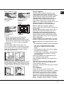
Fitting the appliance
Gas and mixed hobs are manufactured with type X degree
protection against overheating. The following precautions
must be taken when installing the hob:
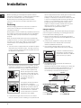
• Kitchen cabinets adjacent to the appliance and taller
than the top of the hob must be at least 600 mm from the
edge of the hob.
• Hoods must be installed according to their relative
installation instruction manuals and at a minimum
distance of 650 mm from the hob.
• Place the wall cabinets adjacent to the hood at a
minimum height of 420 mm from the hob (see figure).
If the hob is installed beneath a
wall cabinet, the latter must be
situated at a minimum of 700 mm
above the hob (see figure).
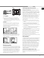
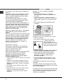
• The installation cavity should have the dimensions
indicated in the figure.
Fastening hooks are provided, allowing you to fasten the
hob to tops that are between 20 and 40 mm thick. To
ensure the hob is securely fastened to the top, we
recommend you use all the hooks provided.
555 mm
55 mm
475 mm
Hook fastening diagram
Hooking position Hooking position
for top H=20 mm for top H=30 mm
Installation
Enlarging the ventilation slot
between window and floor.
Adjacent
Room
Room to be
Vented
A
Examples of ventilation holes
for comburant air.
In a chimney stack or branched flue.
(exclusively for cooking appliances)
Directly to
the Outside
600mm min.
600mm min.
700mm min.

GB
3
Front
Hooking position Back
for top H=40 mm
! Use the hooks contained in the “accessory pack”
• Where the hob is not installed over a built-in oven, a
wooden panel must be installed as insulation. This
must be placed at a minimum distance of 20 mm from
the lower part of the hob.
Ventilation
To ensure adequate ventilation, the back panel of the
cabinet must be removed. It is advisable to install the
oven so that it rests on two strips of wood, or on a
completely flat surface with an opening of at least 45 x
560 mm (see diagrams).
When installing the cooktop above a built-in oven
without forced ventilation, ensure that there are air
inlets and outlets for ventilating the interior of the
cabinet adequately.
Electrical connection
Hobs equipped with a three-pole power supply cable are
designed to operate with alternating current at the voltage
and frequency indicated on the data plate (this is located
on the lower part of the appliance). The earth wire in the
cable has a green and yellow cover. If the appliance is to
be installed above a built-in electric oven, the electrical
connection of the hob and the oven must be carried out
separately, both for electrical safety purposes and to
make extracting the oven easier.
Connecting the supply cable to the mains
Install a standardised plug corresponding to the load
indicated on the data plate.
The appliance must be directly connected to the mains
using an omnipolar circuit-breaker with a minimum contact
opening of 3 mm installed between the appliance and the
mains. The circuit-breaker must be suitable for the charge
indicated and must comply with current electrical
regulations (the earthing wire must not be interrupted by the
circuit-breaker). The supply cable must not come into
contact with surfaces with temperatures higher than 50°C.
! The installer must ensure that the correct electrical
connection has been made and that it is compliant with
safety regulations.
Before connecting to the power supply, make sure that:
• The appliance is earthed and the plug is compliant with
the law.
• The socket can withstand the maximum power of the
appliance, which is indicated on the data plate.
• The voltage is in the range between the values indicated
on the data plate.
• The socket is compatible with the plug of the appliance. If
the socket is incompatible with the plug, ask an
authorised technician to replace it. Do not use extension
cords or multiple sockets.
! Once the appliance has been installed, the power supply
cable and the electrical socket must be easily accessible.
! The cable must not be bent or compressed.
! The cable must be checked regularly and replaced by
authorised technicians only (see Assistance).
! The manufacturer declines any liability should these safety
measures not be observed.
Gas connection
The appliance should be connected to the main gas supply
or to a gas cylinder in compliance with current national
regulations. Before carrying out the connection, make sure
the cooker is compatible with the gas supply you wish to
use. If this is not the case, follow the instructions indicated in
the paragraph “Adapting to different types of gas.”
When using liquid gas from a cylinder, install a pressure
regulator which complies with current national regulations.
! Check that the pressure of the gas supply is consistent
with the values indicated in Table 1 (“Burner and nozzle
specifications”). This will ensure the safe operation and
longevity of your appliance while maintaining efficient
energy consumption.
Connection with a rigid pipe (copper or steel)
! Connection to the gas system must be carried out in such
a way as not to place any strain of any kind on the
appliance.
560 mm.
45 mm.

GB
4
There is an adjustable L-shaped pipe fitting on the
appliance supply ramp and this is fitted with a seal in
order to prevent leaks. The seal must always be replaced
after rotating the pipe fitting (seal provided with
appliance). The gas supply pipe fitting is a threaded 1/2
gas cylindrical male attachment.
Connecting a flexible jointless stainless steel pipe to a
threaded attachment
The gas supply pipe fitting is a threaded 1/2 gas cylindrical
male attachment.
These pipes must be installed so that they are never
longer than 2000 mm when fully extended. Once
connection has been carried out, make sure that the
flexible metal pipe does not touch any moving parts and
is not compressed.
! Only use pipes and seals that comply with current
national regulations.
Checking the tightness of the connection
! When the installation process is complete, check the
pipe fittings for leaks using a soapy solution. Never use a
flame.
Adapting to different types of gas
To adapt the hob to a different type of gas other than
default type (indicated on the rating plate at the base of
the hob or on the packaging), the burner nozzles should
be replaced as follows:
1. Remove the hob grids and slide the burners off their
seats.
2. Unscrew the nozzles using a 7 mm socket spanner,
and replace them with nozzles for the new type of gas
(see table 1 “Burner and nozzle characteristics”).
3. Reassemble the parts following the above procedure in
the reverse order.
4. Once this procedure is finished, replace the old rating
sticker with one indicating the new type of gas used.
Sticker are available from any of our Service Centres.
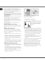
Replacing the Triple ring burner nozzles
1. Remove the pan supports and lift the burners out of
their housing. The burner consists of two separate parts
(see pictures).
2. Unscrew the nozzles using a 7 mm socket spanner.
Replace the nozzles with models that are configured
for use with the new type of gas (see Table 1). The two
nozzles have the same hole diameter.
3. Replace all the components by completing the above
operations in reverse order.
• Adjusting the burners’ primary air :
Does not require adjusting.
• Setting the burners to minimum:
1. Turn the tap to the low flame position.
2. Remove the knob and adjust
the adjustment screw, which is
positioned in or next to the tap
pin, until the flame is small but
steady.
3. Having adjusted the flame to the required low setting,
while the burner is alight, quickly change the position of
the knob from minimum to maximum and vice versa
several times, checking that the flame does not go out.
4. Some appliances have a safety device (thermocouple)
fitted. If the device fails to work when the burners are
set to the low flame setting, increase this low flame
setting using the adjusting screw.
5. Once the adjustment has been made, replace the seals
on the by-passes using sealing wax or a similar
substance.
! If the appliance is connected to liquid gas, the regulation
screw must be fastened as tightly as possible.
! Once this procedure is finished, replace the old rating
sticker with one indicating the new type of gas used.
Stickers are available from any of our Service Centres.
! Should the gas pressure used be different (or vary
slightly) from the recommended pressure, a suitable
pressure regulator must be fitted to the inlet pipe (in order
to comply with current national regulations).

GB
5
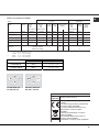
Table 1 Liquid Gas Natural Gas
Burner Diameter Thermal Thermal By-pass Nozzle Flow* Thermal Nozzle Flow*
power power 1/100 1/100 (g/h) power 1/100 (l/h)
kW kW kW
(p.c.s.*) (p.c.s.*) (p.c.s.*)
(mm) Reduced Nominal (mm) (mm) *** ** Nominal (mm)
Supply pressures
Nominal (mbar)
Minimum (mbar)
Maximum (mbar)
28-30
20
35
37
25
45
20
17
25
Fast (R)
Reduced Fast (RR)
Semi Fast (S)
Auxiliary (A)
Triple Crown (TC)
100
100
75
55
130
0.70
0.70
0.40
0.40
1.50
3.00
2.60
1.65
1.00
3.30
39
39
28
28
61
86
80
64
50
65x2
218
189
120
73
240
214
186
118
71
236
3.00
2.60
1.65
1.00
3.30
132 (H)
122 (H)
96
79 (6)
103x2
286
248
157
95
343
Burner and nozzle specifications
* At 15°C and 1013 mbar - dry gas
** Propane P.C.S. = 50.37 MJ/Kg
*** Butane P.C.S. = 49.47 MJ/Kg
Natural P.C.S. = 37.78 MJ/m³
PC 640 X/HA TK
PC 640 /HA TK
R
S
S
A
PC 640 T X/HA TK
PC 640 T /HA TK
RR
TC
S
A
Electrical
connections
DATA PLATE
see data plate
This appliance conforms to the following
European Economic Community directives:
- 2006/95/EEC dated 12/12/06 (Low
Voltage) and subsequent amendments
- 2004/108/EEC dated 15/12/04
(Electromagnetic Compatibility) and
subsequent amendments
- 93/68/EEC dated 22/07/93 and
subsequent amendments.
- 2009/142/EEC dated 30/11/09 (Gas) and
subsequent amendments.
- 2002/96/EC and subsequent
amendments.

GB
6
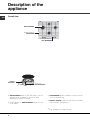
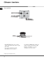
Description of the
appliance
Overall view
*
Only available on certain models.
• GAS BURNERS differ in size and power. Use the
diameter of the cookware to choose the most
appropriate burner to cook with.
• Control Knobs for GAS BURNERS adjust the size
of the flame.
SAFETY
DEVICES *
Ignition for
GAS BURNERS *
Support Grid for
COOKWARE
Control Knobs for
GAS BURNERS
GAS BURNERS
• GAS BURNER ignition* enables a specific burner
to be lit automatically.
• SAFETY DEVICE* stops the gas flow if the flame
is accidentally extinguished.

GB
7
! The position of the corresponding gas burner or
electric hotplate* is shown on every knob.
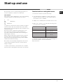
Gas burners
Each burner can be adjusted to one of the following
settings using the corresponding control knob:
• Off
Maximum
Minimum
To light one of the burners, hold a lit match or lighter
near the burner and, at the same time, press down
and turn the corresponding knob anti-clockwise to the
maximum setting.
Since the burner is fitted with a safety device, the
knob should be pressed for approximately 2-3
seconds to allow the automatic device keeping the
flame alight to heat up.
When using models with an ignition button, light the
desired burner pressing down the corresponding
knob as far as possible and turning it anticlockwise
towards the maximum setting.
! If a flame is accidentally extinguished, turn off the
control knob and wait for at least 1 minute before
trying to relight it.
To switch off the burner, turn the knob in a clockwise
direction until it stops (when reaches the “•” position).
Practical advice on using the burners
To ensure the burners operate efficiently:
• Use appropriate cookware for each burner (see
table) so that the flames do not extend beyond
the bottom of the cookware.
• Always use cookware with a flat base and a cover.
• When the contents of the pan reach boiling point,
turn the knob to minimum.
Burner
Rapid (R)
Reduced Rapid (RR)
Semi-Rapid (S)
Auxiliary (A)
Triple Crown (TC)
Ø Cookware Diameter (cm)
24 - 26
24 - 26
16 - 20
10 - 14
24 - 26
To identify the type of burner, refer to the designs in
the section entitled, "Burner and Nozzle
Specifications".
Start-up and use

GB
8
Precautions and tips
! This appliance has been designed and manufactured
in compliance with international safety standards. The
following warnings are provided for safety reasons and
must be read carefully.
General safety
• This is a class 3 built-in appliance.
• Gas appliances require regular air exchange to
maintain efficient operation. When installing the
hob, follow the instructions provided in the
paragraph on “Positioning” the appliance.
• These instructions are only valid for the countries
whose symbols appear in the manual and on the
serial number plate.
• The appliance was designed for domestic use inside
the home and is not intended for commercial or
industrial use.
• The appliance must not be installed outdoors, even in
covered areas. It is extremely dangerous to leave the
appliance exposed to rain and storms.
• Do not touch the appliance with bare feet or with wet
or damp hands and feet.
• The appliance must be used by adults only for the
preparation of food, in accordance with the
instructions outlined in this booklet. Any other
use of the appliance (e.g. for heating the room)
constitutes improper use and is dangerous. The
manufacturer may not be held liable for any
damage resulting from improper, incorrect and
unreasonable use of the appliance.
• Ensure that the power supply cables of other
electrical appliances do not come into contact with
the hot parts of the oven.
• The openings used for ventilation and dispersion of
heat must never be covered.
• Always make sure the knobs are in the “”/“
”
position when the appliance is not in use.
• When unplugging the appliance always pull the plug
from the mains socket, do not pull on the cable.
• Never carry out any cleaning or maintenance work
without having detached the plug from the mains.
• In case of malfunction, under no circumstances
should you attempt to repair the appliance yourself.
Repairs carried out by inexperienced persons may
cause injury or further malfunctioning of the
appliance. Contact a Service Centre (see
Assistance).
• Always make sure that pan handles are turned
towards the centre of the hob in order to avoid
accidental burns.
• Do not close the glass cover (if present) when the gas
burners are still hot.
• Do not use unstable or deformed pans.
• Remove any liquid from the lid before
opening it.
• Prevent children and the disabled from coming into
contact or having access at the ceramic glass
cooking surface (if present) immediately before and
after use, as the cooking surface will remain hot for at
least a half hour after being turned off;
• The appliance should not be operated by people
(including children) with reduced physical, sensory or
mental capacities, by inexperienced individuals or by
anyone who is not familiar with the product. These
individuals should, at the very least, be supervised
by someone who assumes responsibility for their
safety or receive preliminary instructions relating to
the operation of the appliance.
• Do not let children play with the appliance.
• The appliance is not intended to be operated by
means of an external timer or separate remote-
control system.
Disposal
• When disposing of packaging material: observe local
legislation so that the packaging may be reused.
• The European Directive 2002/96/EC on Waste
Electrical and Electronic Equipment (WEEE), requires
that old household electrical appliances must not be
disposed of in the normal unsorted municipal waste
stream. Old appliances must be collected separately
in order to optimise the recovery and recycling of the
materials they contain and reduce the impact on
human health and the environment. The crossed out
“wheeled bin” symbol on the product reminds you of
your obligation, that when you dispose of the
appliance it must be separately collected.
Consumers may take their old appliance to public
waste collection areas, other communal collection
areas, or if national legislation allows return it to a
retailer when purchasing a similar new product.
All major household appliance manufacturers are
active in the creation of systems to manage the
collection and disposal of old appliances.

GB
9
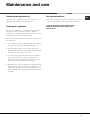
Switching the appliance off
Disconnect your appliance from the electricity
supply before carrying out any work on it.
Cleaning the appliance
! Do not use abrasive or corrosive detergents such
as stain removers, anti-rust products, powder
detergents or sponges with abrasive surfaces: these
may scratch the surface beyond repair.
! Never use steam cleaners or pressure cleaners on
the appliance.
• It is usually enough to wash the hob with a damp
sponge and dry it with absorbent kitchen roll.
• The removable parts of the burners should be
washed frequently with warm water and soap and
any burnt-on substances removed.
• For hobs which ligth automatically, the terminal
part of the electronic instant lighting devices
should be cleaned frequently and the gas outlet
holes should be checked for blockages.
• Stainless steel can be marked by hard water that
has been left on the surface for a long time, or by
aggressive detergents containing phosphorus.
After cleaning, rinse and dry any remaining drops
of water.
Maintenance and care
Gas tap maintenance
Over time, the taps may become jammed or difficult
to turn. If this happens, the tap must be replaced.
! This procedure must be performed by a
qualified technician authorised by the
manufacturer.

GB
10
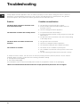
Troubleshooting
It may happen that the appliance does not function properly or at all. Before calling the service centre for
assistance, check if anything can be done. First, check to see that there are no interruptions in the gas and
electrical supplies, and, in particular, that the gas valves for the mains are open.
Problem
The burner does not light or the flame is not
even around the burner.
The flame dies in models with a safety device.
The burner does not remain lit when set to
minimum.
The cookware is unstable.
Possible causes/Solution
• The gas holes on the burner are clogged.
• All the movable parts that make up the burner are
mounted correctly.
• There are draughts near the appliance.
• You pressed the knob all the way in.
• You keep the knob pressed in long enough to activate the
safety device.
• The gas holes are not blocked in the area corresponding
to the safety device.
• The gas holes are not blocked.
• There are no draughts near the appliance.
• The minimum setting has been adjusted properly.
• The bottom of the cookware is perfectly flat.
• The cookware is positioned correctly at the centre of the
burner.
• The pan support grids have been positioned correctly.
If, despite all these checks, the hob does not function properly and the problem persists, call the nearest
Customer Service Centre. Please have the following information handy:
• The appliance model (Mod.).
• The serial number (S/N).
This information can be found on the data plate located on the appliance and/or on the packaging.
! Never use unauthorised technicians and never accept replacement parts which are not original.

TR
11
SETÜSTÜ
PC 640/HA TK
PC 640 X/HA TK
PC 640 T X/HA TK
PC 640 T /HA TK
Ýçindekiler
Montaj, 12-15
Yerleþtirme
Elektrik baðlantýsý
Gaz baðlantýsý
Özellikler etiketi
Brülör ve memelerin özellikleri
Cihazýn tanýtýmý, 16
Genel görünüþ
Cihazýn çalýþtýrýlmasý ve kullanýlmasý, 17
Brülörlerin kullanýmý için pratik tavsiyeler
Önlemler ve tavsiyeler, 18
Genel emniyet
Ýmha
Servis ve bakým, 19
Elektrik akýmýnýn devre dýþý býrakýlmasý
Cihazýn temizlenmesi
Gaz vanalarýnýn bakýmý
Arýzalar ve çözümler, 20
Kullaným talimatlarý
English,1
GB
TR
Türkçe, 11

12
TR
! Her gerektiðinde baþvurulabilmesi için bu el kitapçýðýnýn
muhafaza edilmesi önemlidir. Cihazýn satýlmasý, baþkasýna
verilmesi ya da taþýnmasý durumunda yeni kullanýcýnýn
iþleyiþ ve iliþkin uyarýlar hakkýnda bilgi edinmesi için el
kitapçýðýnýn cihazla birlikte verildiðinden emin olunuz.
! Talimatlarý dikkatli bir þekilde okuyunuz: kurulum,
kullaným ve emniyet hakkýnda önemli bilgiler içermektedir.
Yerleþtirme
! Ambalajlar çocuklarýn oyuncaðý deðildir ve ayrýþtýrýlmýþ
çöp için belirlenen kurallara uygun olarak imha edilmelidirler
(bakýnýz Önlem ve tavsiyeler).
! Kurulum iþlemi bu talimatlar doðrultusunda ve profesyonel
olarak kalifiye personel tarafýndan yapýlmalýdýr. Hatalý
yapýlan bir kurulum, insan ve hayvan saðlýðýna ya da mala
zarar verebilir.
! Bu cihaz, yürürlükteki Ulusal Normlar ve
yürürlükteki müteakip güncellemeler çerçevesinde
sadece sürekli olarak havalandýrýlan mekânlarda
monte edilebilir ve çalýþtýrýlabilir. Aþaðýdaki þartlar
yerine getirilmelidir:
• Mekân ateþleme dumanlarýnýn dýþarýya atýlmasýný
saðlayan, cihaz açýldýðýnda otomatik olarak devreye
giren elektrikli bir vantilatör ya da davlumbaz vasýtasýyla
oluþturulmuþ bir tahliye sistemine sahip olmalýdýr.
• Mekân, ateþleme iþleminin düzgün bir þekilde
gerçekleþmesi için gerekli olan hava akýmýný
saðlayacak bir sisteme sahip olmalýdýr. Yanma iþlemi
için gerekli olan hava miktarý, monte edilmiþ olan her
kW güç baþýna 2 m
3
/h’nin altýnda olmamalýdýr.
Sistem, en az 100 cm
2
kesitinde
ve istem dýþý týkanmayacak
þekilde kurulu bir boru vasýtasýyla
bina dýþýndan doðrudan hava
almak suretiyle gerçekleþtirilebilir.
Veya, dolaylý olarak, bitiþik
mekânlarda mevcut olan yukarýda
anlatýlan türden bir dýþarýya
açýlma sistemi bulunan bir
havalandýrma borusu kullanýlabilir;
bu havalandýrma borusu gayri
menkulün müþterek kullanýmýnda,
ya da yangýn tehlikesi olan
mekânlarda ya da yatak
odalarýnda olmamalýdýr.
• Sývýlaþtýrýlmýþ petrol gazlarý, havadan daha aðýr
olduklarýndan, aþaðýya doðru çökerler. Dolayýsýyla LPG
tüpleri bulunan mekânlarda dýþarý açýlan bu pencereler,
olasý gaz kaçaklarýný aþaðý kýsýmdan tahliye edecek
þekilde ayarlanmalýdýrlar. Bu nedenle boþ ya da kýsmen
dolu LPG bidonlarý, zemin seviyesi altýnda bulunan
mekân yada odalara monte edilmemeli veya
depolanmamalýdýrlar (bodrumlar, vb.). Mekânda sadece
kullanýlmakta olan tüpü bulundurmak uygundur; ayrýca
bu tüp 50°C derece ve üzerindeki sýcaklýk derecelerine
ulaþmasýna neden olacak doðrudan ýsý kaynaklarýna
(fýrýn, þömine, soba) maruz býrakýlmamalýdýr.
Yuvaya oturtma
Gazlý ve karýþýk set üstü ocaklar, X türünden aþýrý
ýsýnmaya dayanýklý koruma seviyesine sahip olarak
donatýlmýþ olduðundan yüksekliði kendi çalýþma
yüzeyinden daha yüksek olmayan mobilyalarýn yanýna
monte edilebilir. Set üstü ocaðýn doðru þekilde monte
edilebilmesi için aþaðýdaki þartlara uyulmalýdýr:
• Yan tarafta bulunan ve yüksekliði ocaðýn çalýþma
yüzeyini aþan dolaplar ocaðýn kenarýndan en az
600 mm mesafede bulunmalýdýr.
• Davlumbazlar kendi talimat kitapçýklarýnda yer
alan özelliklere uygun olarak ve en az 650 mm
boþluk býrakýlarak monte edilmelidir.
• Davlumbaz yanýndaki sarkýklarý tezgah
zemininden minimum 420 mm yukarýya
yerleþtiriniz (þekle bakýnýz).
Set üstü ocaðýn bir sarkýk
altýna gelecek þekilde monte
edilmesi durumunda, bu
sarkýkýn tezgâh yüzeyine
mesafesi en az yaklaþýk 700
mm olmalýdýr (þekle bakýnýz).
• Mobilya boþluðu þekilde gösterilen boyutlarda
olmalýdýr. Set üstü ocak tezgah üzerine
yerleþtirilmesi amacýyla 20 mm - 40 mm
kalýnlýðýnda sabitleme kancalarý ile donatýlmýþtýr.
Tezgahý saðlam bir þekilde sabitlemek için mevcut
olan kancalarýn kullanýlmasý tavsiye edilir.
555 mm
55 mm
475 mm
Kurulum
Kapý ve yer arasýnda
yükseltilmiþ boþluk
Bitiþik oda Havalandýrýlmasý
gereken oda
A
Yakıcı hava dolaşımını
sağlayan ağızlık örneği
Bacadan veya (pişirme cihazlarında)
duman kanalından
Doğrudan
dışarıya
600mm min.
600mm min.
700mm min.

TR
13
Kanca sabitleme þemasý
Ön taraf
Arka taraf
! “Aksesuar paketi”nde bulunan kancalarý kullanýnýz
• Set üstü ocaðýn ankastre fýrýn üzerine monte
edilmemesi durumunda, izolasyon amacýyla bir ahþap
levhanýn takýlmasý gerekmektedir. Bu levha tezgahýn alt
kýsmýndan en az 20 mm. mesafeye yerleþtirilmelidir.
Havalandýrma
Ýyi bir havalandýrma saðlanmasý için yuvanýn arka
duvarýnýn çýkarýlmasý gerekir. Fýrýnýn kurulumun iki ahþap
pervaz üzerine ya da en az 45 x 560 mm ebatlarýnda bir
açýklýðý olan bir zemine yaslanacak þekilde yapýlmasý
tercih edilir (þekillere bakýnýz).
Havalandýrma sistemi olmadan ankastre fýrýn üzerine
kurulum yapýlmasý halinde, dolabýn içinde uygun bir
hava dolaþýmýnýn saðlanmasý için hava giriþ ve çýkýþ
noktalarý kesinlikle ayarlanmalýdýr (þekillere bakýnýz).
Elektrik baðlantýsý
Üç kutuplu besleme kablosuyla donatýlmýþ set üstü
ocaklar, özellikler etiketi (set üstü ocaðýn alt kýsmýna
yerleþtirilmiþtir) üzerinde belirtilmiþ olan gerilim ve besleme
frekansý deðerlerinde dalgalý akýmla çalýþacak þekilde
üretilmiþtir. Kablonun topraklama iletkeni sarý-yeþil
renklerindedir. Setüstü ocaðýn ankastre bir fýrýn üzerine
monte edilmesi durumunda, fýrýn ile ocaðýn elektrik
baðlantýsý, hem elektrik emniyeti açýsýndan hem de fýrýnýn
çýkarýlmasý gerektiðinde bu iþlemin daha kolay
yapýlabilmesi amacýyla ayrý ayrý gerçekleþtirilmelidir.
Besleme kablosunun þebekeye baðlantýsý
Kabloya özellikler etiketi üzerinde belirtilen yüke uygun bir
fiþ monte ediniz.
Þebekeye doðrudan baðlantý yapýlmasý halinde, cihaz ile
þebeke arasýna minimum temas aralýðý 3 mm olan ve
yürürlükteki normlara uygun nitelikte çok kutuplu bir
anahtar takmak gerekmektedir (toprak kablosu elektrik
anahtarý tarafýndan kesintiye uðratýlmamalýdýr). Besleme
kablosu, hiçbir aþamada ortam ýsýsýný 50°C geçmeyecek
þekilde yerleþtirilmelidir.
! Elektrik baðlantýsýnýn doðru yapýlmasýndan ve güvenlik
kurallarýna uyulmasýndan kurulumu yapan kiþi sorumludur.
Þebekeye baðlamadan önce aþaðýdaki durumlarý kontrol
ediniz:
• prizin topraklamasýnýn yürürlükteki normlara uygun olduðunu;
• prizin, cihazýn özellikler etiketi üzerinde belirtilen
maksimum güç miktarýný destekleyecek þekilde
olduðunu;
• besleme geriliminin özellikler etiketi üzerinde belirtilmiþ
olan deðerler arasýnda olduðunu;
• cihaz fiþinin prizle uyumlu olduðunu. Aksi hallerde prizi
ya da fiþi deðiþtiriniz; uzatma kablolarý ya da çoklu
prizler kullanmayýnýz.
! Cihaz monte edildikten sonra elektrik kablosu ve priz
kolay eriþilebilecek yerlerde olmalýdýr.
! Kablo kývrýlmalara, bükülmelere veya ezilmelere maruz
kalmamalýdýr.
! Kablo periyodik olarak kontrol edilmeli ve sadece
yetkili teknik personel tarafýndan deðiþtirilmelidir
(Destek bölümüne bakýnýz).
! Bu kurallara uyulmamasý halinde firma hiç bir sorumluluk
kabul etmez.
Gaz baðlantýsý
Cihazýn gaz tüpüne yada gaz hattý borusuna
baðlanmasý yürürlükteki Ulusal Normlara ve müteakip
güncellemelere uygun olarak yapýlmalý ve baðlantý
öncesi cihazýn kullanýlacaðý gaz tipine ayarlanmýþ
olduðu kontrol edilmelidir. Aksi takdirde “Farklý gaz
tiplerine uyum” paragrafýnda belirtilen iþlemleri yerine
getiriniz. Sývý gazla, yani gaz tüpünden beslenmesi
halinde, yürürlükteki Ulusal Normalara ve müteakip
560 mm.
45 mm.
Çalýþma tezgahý için
kanca pozisyonu
H=20mm
Çalýþma tezgahý için
kanca pozisyonu
H=30mm
Setüstü ocak için
kanca pozisyonu
H=40mm

14
TR
güncellemelere uygun tipteki basýnç regülatörlerini
kullanýnýz.
! Emniyetli bir çalýþma, uygun enerji kullanýmý ve cihazýn
ömrünün uzun olmasý için, besleme basýncýnýn tablo 1
“Brülör ve memelerin özellikleri”nde gösterilen deðerler
arasýnda olduðundan emin olunuz.
Sert bir boru ile baðlantý (bakýr ya da çelik)
! Gaz tesisatýna baðlantý cihazda hiçbir türden zorlama
yaratmayacak þekilde gerçekleþtirilmelidir.
Cihazýn besleme rampasý üzerinde, yönlendirilebilir bir “L”
rakoru bulunmaktadýr, bunun sýzdýrmazlýðý da bir conta ile
saðlanmýþtýr. Rakorun döndürülmesine gerek duyulmasý
halinde, sýzdýrmazlýk contasý mutlaka deðiþtirilmelidir
(cihazla birlikte verilmiþtir). Cihazýn gaz giriþ rakoruna
silindirik 1/2 erkek diþ açýlmýþtýr.
Paslanmaz çelikten esnek boru ile yivli baðlantý
uçlarý kullanarak yapýlan kesintisiz duvara
baðlantý
Cihazýn gaz giriþ rakoruna silindirik 1/2 erkek diþ açýlmýþtýr.
Bu borular, kullanýmlarý sýrasýnda, uzunluklarý maksimum
2000 mm’yi geçmeyecek þekilde döþenmelidir. Baðlantý
yapýldýðýnda esnek metal borunun hareketli parçalar ile
temas etmediðinden veya ezilmediðinden emin olunuz.
! Sadece yürürlükteki Ulusal Normlara uygun
alüminyum sýzdýrmaz borular ve contalar veya
kauçuk contalar kullanýnýz.
Sýzdýrmazlýk kontrolü
! Montaj iþlemi tamamlandýðýnda, alev kullanýlmadan,
yalnýz sabunlu su solüsyonu kullanmak suretiyle tüm
rakorlara sýzdýrmazlýk kontrolü yapýnýz.
Farklý gaz tiplerine uyarlama
Setüstü ocaðýn üretimde ayarlanmýþ olduðu gazdan farklý
gaz tiplerine ayarlanmasý için (ilk ayarý ocaðýn alt
kýsmýndaki ya da ambalajýn üzerindeki etikette
belirtilmiþtir), aþaðýdaki iþlemlerin yapýlarak brülörlerin
memelerinin deðiþtirilmesi gerekir:
1. ocaðýn ýzgaralarýný alýnýz ve brülörleri yuvalarýndan
çýkartýnýz.
2. 7 mm’lik bir boru anahtarý kullanarak memeleri
sökünüz ve yeni gaz tipine uyarlanmýþ olanlarla
deðiþtiriniz (bakýnýz tablo 1 “Brülör ve memelerin
özellikleri”).
3. ayný iþlemleri tersine yaparak parçalarý tekrar
monte ediniz.
4. bu iþlemin sonunda, eski ayarý gösteren etiketi,
Teknik Servis Merkezlerimizden temin
edilebilecek, yeni gaz tipini gösteren etiketle
deðiþtiriniz.
Bagýmsýz ‘Üç Taçlý’ ocaklarda agýzlýklarýn
degistirilmesi
1. ocagýn ýzgaralarýný sökünüz ve ocak gözlerini
yuvasýndan çýkarýnýz. Ocak iki ayrý parçadan olusur
(bkz. sekil);
2. 7 mm.lik boru anahtarý vasýtasýyla agýzlýklarý
sökünüz. Agýzlýklarý yeni gaz türüne uygun olanla
degistiriniz(bkz. çizelge 1). Iki uçlarýný ayný delik
var.
3. Ters prosedürü uygulayarak tüm parçalarý yeniden
yerlestiriniz.
• Brülörlerin birincil hava ayarlanmasý
Brülörlere ilk hava ayarý yapýlmasýna gerek yoktur.
• Minimum ayarlamasý
1. Gaz vanasýný minimum konumuna getiriniz;
2. Düðmeyi söküp vana
milinin iç tarafýnda ya da
yanýnda bulunan ayar vidasýna
küçük ve düzenli bir alev elde
edene kadar müdahale ediniz.
3. Düðmeyi maksimum pozisyondan minimum pozisyona
döndürünce brülörlerin sönmediðinden emin olunuz.
4. Emniyet aygýtý olan cihazlarda (ýsý pili), brülörler
minimum konumdayken bu aygýtýn çalýþmamasý
durumunda, ayar vidasýna müdahale ederek
minimumlarý yükseltiniz.
5. Ayar iþlemi bittiðinde by-pass’lar üzerinde yer alan
mumlu ya da benzer malzemeli mühürleri eski haline
getiriniz.
! Sývý gaz kullanýmý halinde ayar vidasý sonuna kadar
sýkýlmalýdýr.
! Bu iþlemin sonunda, eski ayarý gösteren etiketi, Teknik
Servis Merkezlerimizden temin edilebilecek, yeni gaz tipini
gösteren etiketle deðiþtiriniz.
! Kullanýlan gaz basýncýnýn öngörülen basýnçtan farklý
(ya da deðiþken) olmasý halinde, giriþ borusu üzerine
uygun bir basýnç regülatörü takýlmalýdýr (uyarýnca
“kanalize gaz regülatörleri”).

TR
15
PC 640 X/HA TK
PC 640 /HA TK
R
S
S
A
PC 640 T X/HA TK
PC 640 T /HA TK
RR
TC
S
A
Tablo
1
Sývý gaz
Doðal gaz
Brülör
Çap
Termik
Termik
By-pass
Meme
Tasima gücü
*
Termik
Meme
Tasima
güç
güç
1/100 1/100 (g/saat)
güç
1/100
gücü
*
kW kW kW (l/saat)
(
üst ýsý gücü*
) (
üst ýsý gücü*
) (
üst ýsý gücü*
)
(mm)
Azaltýlmý
Nominal (mm) (mm) *** ** Nominal (mm)
Besleme
basýnçlarý
Nominal (mbar)
Minimum (mbar)
Maksimum (mbar)
28-30
20
35
37
25
45
20
17
25
Hýzlý(Büyük) (R)
Azaltýlmýþ Hýzlý
(RR)
Yarý hýzlý (Orta) (S)
Yardýmcý (Küçük) (A)
Üç Taçlý
(TC)
100
100
75
55
130
0.70
0.70
0.40
0.40
1.50
3.00
2.60
1.65
1.00
3.30
39
39
28
28
61
86
80
64
50
65x2
218
189
120
73
240
214
186
118
71
236
3.00
2.60
1.65
1.00
3.60
132 (H)
122 (H)
96
79 (6)
103x2
286
248
157
95
343
* 15°C ve 1013 mbar’da-kuru gaz
** Propan P.C.S. = 50.37 MJ/Kg
*** Bütan P.C.S. = 49.47 MJ/Kg
Doðal P.C.S. = 37.78 MJ/m³
Brülör ve memelerin özellikleri
Model Gaz bölümü
Sınıf Güç (kW)
II2H3+
II2H3+
PC 640 X/HA TK
PC 640 /HA TK
PC 640 T X/HA TK
PC 640 T /HA TK
7,30 (567 g/h - G30)
(557 g/h - G31)
8,55 (567 g/h - G30)
(557 g/h - G31)
(1) g/h değerleri likit gaz (Bütan, Propan) kapasitelerine bakın.
Elektrik
bağlantıları
ÖZELLİKLER ETİKETİ
özellikler etiketine bakınız
Bu cihaz asagidaki Avrupa Birligi Direktiflerine
uygundur:
- 12/12/06 tarihli (Alçak Basinç) 2006/95/CEE
ve üzerinde yapilan degisiklikler
- 15/12/04 tarihli (Elektromanyetik Uyum)
2004/108/CEE ve üzerinde yapilan
degisiklikler
- 22/07/93 tarihli 93/68/CEE ve üzerinde
yapilan degisiklikler.
- 30/11/09 tarihli 2009/142/CEE (Gaz) ve
üzerinde yapilan degisiklikler.
- 2002/96/CE ve üzerinde yapilan degisiklikler.

16
TR
Cihazýn tanýtýmý
Genel görünüm
*
Sadece bazý modellerde mevcut.
• GAZ BRÜLÖRLERÝ farklý ebat ve güçlere
sahiptir. Kullanacaðýnýz kabýn çapýna en uygun
olaný seçiniz.
• Alev ve gücün ayarlanmasý için GAZ
BRÜLÖRLERI kumanda düðmeleri *.
• Gaz brülörleri ÇAKMAKLARI* seçilmiþ olan
brülörün otomatik olarak yakýlmasýný saðlar.
• EMNIYET DONANIMI* alev kazara
söndüðünde, gaz çýkýþýný durdurur.
EMNİYET
DÜZENEĞİ *
GAZ BRÜLÖRLERİ
yakma bujisi*

TR
17
! Her bir düðme üzerinde kumanda ettiði gaz
brülörünün ya da elektrikli levhanýn* konumu
belirtilmiþtir.
Gaz brülörleri
Seçilmiþ olan brülör, ilgili düðme vasýtasýyla
aþaðýdaki konumlara ayarlanabilir:
• Kapalý
Maksimum
Minimum
Brülörlerin birini yakmak için bir çakmak ya da alevi
brülöre yaklaþtýrýnýz, düðmeye basýlý tutarak
maksimum güç pozisyonuna getirene kadar saat
yönünün tersinde döndürünüz.
Emniyet donanýmý bulunan modellerde, alevin
otomatik olarak yanýk kalmasýný saðlayan donaným
ýsýnýncaya kadar düðmeyi yaklaþýk 2-3 saniye basýlý
tutmanýz gerekmektedir.
Ateþleme bujisi mevcut olan modellerde, seçilmiþ
olan brülörü yakmak için öncelikle
sembollü
yakma tuþuna basýnýz, daha sonra ilgili düðmeye
basýlý tutarak maksimum güç pozisyonuna gelene
kadar saat yönünün tersinde döndürünüz.
! Brülör alevlerinin beklenmedik þekilde sönmesi
durumunda kontrol düðmesini kapatýnýz ve en az 1
dakika bekledikten sonra tekrar yakmayý deneyiniz.
Brülörü kapatmak için, düðmeyi durana kadar saat
yönünde döndürmeniz gerekmektedir (“•” sembolüne
gelene kadar ).
Brülörlerin kullanýmý için pratik
tavsiyeler
En yüksek performansý elde edebilmek amacýyla
aþaðýdaki hususlarý aklýnýzdan çýkarmayýnýz:
• kaplarýn altýndan alevlerin çýkmasýný önlemek
amacýyla her brülöre uygun kaplar (tabloya
bakýnýz) kullanýnýz.
• her zaman altý düz ve kapaklý kaplar kullanýnýz.
• kaynama esnasýnda düðmeyi minimum pozisyona
kadar döndürünüz.
Ocak
Hýzlý (R)
Azaltýlmýþ Hýzlý (RR)
Yarý Hýzlý (S)
Yardýmcý (A)
Üç Taçlý (TC)
Ø Kap çapý (cm)
24 - 26
24 - 26
16 - 20
10 - 14
24 - 26
Brülör tipini belirlemek için “Brülör ve memelerin
özellikleri” paragragfýnda mevcut olan þekillere
baþvurunuz.
Baþlatma ve kullaným

18
TR
Önlemler ve tavsiyeler
! Cihaz uluslararasý emniyet mevzuatlarýna uygun
olarak projelendirilmiþ ve üretilmiþtir. Bu uyarýlar
güvenlik amaçlý olup dikkatlice okunmalýdýr.
Genel emniyet
• Bu cihaz, 3. sýnýf ankastre cihazlara
dahildir.
• Gazla çalýþan cihazlar, düzgün bir çalýþma
için düzenli hava deðiþimine ihtiyaç
duyarlar. Montaj sýrasýnda “Yerleþtirme”
bölümüne iliþkin paragrafta belirtilmiþ olan
þartlara uyulduðundan emin olunuz.
• Verilmiþ olan talimatlar sadece kitapçýkta
ve sicil plakasýnda sembolü bulunan ülkeler
için geçerlidir.
• Cihaz, meskenlerde kullanýlmak üzere tasarlanmýþ
olup profesyonel kullaným amaçlý deðildir.
• Yaðmur ve fýrtýnaya maruz kalmasý son derece
tehlikeli olduðundan cihaz, üzeri kapalý bile olsa
açýk alanlara monte edilemez.
• Cihaza ayaklarýnýz çýplakken ya da elleriniz veya
ayaklarýnýz ýslak ya da nemliyken dokunmayýnýz.
• Cihaz, sadece yetiþkin kiþiler tarafýndan ve
bu kitapçýkta aktarýlan talimatlara göre,
yemek piþirmek amaçlý kullanýlmalýdýr. Her
türlü diðer kullanýmlar (örneðin: ortam
ýsýtmasý) uygunsuz ve bu nedenle tehlikeli
bulunur. Üretici firma uygunsuz, hatalý ve
mantýk dýþý kullanýmlardan kaynaklanan
muhtemel zararlardan sorumlu tutulamaz.
• Diðer beyaz eþyalara ait kablolarýn fýrýnýn sýcak
kýsýmlarýna temas etmesini önleyiniz.
• Havalandýrma ve ýsý daðýlma noktalarýný
týkamayýnýz.
• Cihazýn kullanýlmadýðý zamanlarda düðmelerin
daima “”/“
” konumunda olduðundan emin
olunuz.
• Fiþi prizden çekerken kablosundan deðil fiþin
kendisinden tutarak çekiniz.
• Fiþi elektrik þebekesinden çekmeden, temizlik
veya bakým müdahalelerinde bulunmayýnýz.
• Arýza halinde onarmak amacýyla iç mekanizmalarý
kurcalamayýnýz. Teknik servis ile irtibata geçiniz
(Teknik servis bölümüne bakýnýz).
• Kazayla darbeye maruz kalmalarýný önlemek için
tencere kulplarýnýn daima ocaðýn içine doðru
dönük olduðundan emin olunuz.
• Cam kapaðý (mevcut olduðu durumlarda) gaz
brülörleri ya da elektrikli levha hala sýcakken
kapatmayýnýz.
• Elektrik levhasýný üzerinde tencere olmadan yanýk
býrakmayýnýz.
• Yerine oturmayan ya da deforme olmuþ tencereleri
kullanmayýnýz.
• Cihaz harici bir otomatik zaman ayarý veya ayrý bir
uzaktan kumanda sistemi ile çalýþtýrýlacak þekilde
tasarlanmamýþtýr.
Ýmha
• Ambalaj malzemelerinin imha edilmesi:
ambalajlarýn geri dönüþümünü saðlayan yerel
düzenlemelere uyunuz.
• Elektrik ve elektronik cihazlarýn atýklarýný
deðerlendirme konusunu düzenleyen 2002/96/CE
sayýlý Avrupa Birliði mevzuatýnda; beyaz eþyalarýn
kentsel katý atýk genel yöntemi ile imha
edilmemesi öngörülmüþtür. Kullanýlmayan cihazlar,
madde geri kazaným ve geri dönüþüm oranýný en
yüksek seviyeye yükseltmek, çevre ve insan
saðlýðýna olasý zararlarý engellemek için ayrý ayrý
toplanmasý gerekir. Tüm ürünlerin üzerinde;
ayrýþtýrýlmýþ atýk hükümlerini hatýrlatmak amacýyla
üstünde çarpý iþareti olan sepet sembolü yer
almaktadýr.
Kullanýlmayan beyaz eþyalar belediye atýk toplama
servisine teslim edilebilecektir, bunlarý belediyenin
bunun için özel olarak belirlediði yerlere ya da
konuyla ilgili ulusal düzenlemelerin mevcut olduðu
durumlarda, benzer tipte yeni bir ürün aldýðýnýz
satýcýlara verebilirsiniz.
Belli baþlý tüm beyaz eþya üreticileri kullanýlmayan
cihazlarýn toplanmasý ve imha edilmesi için
öngörülen sistemlerin oluþturulmasý ve idaresi
konusunda faaliyet göstermektedir.

TR
19
Elektrik akýmýnýn devre dýþý býrakýlmasý
Herhangi bir iþlem yapmadan önce cihazýn elektrik
þebekesine baðlantýsýný kesiniz.
Cihazýn temizlenmesi
! Pas önleyici, leke çýkarýcý ürünler gibi çizici ve
aþýndýrýcý özellikte malzemeler, toz deterjanlar ve
aþýndýrýcý yüzeyli süngerler kullanmaktan kaçýnýnýz:
bunlar, yüzeyin onarýlmayacak þekilde çizilmesine
yol açabilir.
! Cihazýn temizliði için asla buharlý ya da yüksek
basýnçlý temizleyiciler kullanmayýnýz.
• Olaðan bakým iþlemleri için setüstü ocaðý nemli bir
süngerle yýkamak ve emici kâðýt havlu ile
kurulamak yeterlidir.
• Brülörlerin hareketli parçalarý, muhtemel kireç
birikintilerinin çözülmesine dikkat edilerek sýcak su
ve deterjanla sýk sýk yýkanmalýdýr.
• Otomatik ateþlemeli setüstü ocaklarda, elektronik
anýnda ateþleme sisteminin terminal kýsmý sýk sýk
ve özenle temizlenmeli ve gaz çýkýþlarýnýn
týkanmamýþ olduðundan emin olunmalýdýr.
• Ýnox çelik malzeme, kireç oraný yüksek su ya da
aþýndýrýcý deterjanlarla (fosfor içeren) uzun süre
temas etmesi halinde lekeli kalabilir. Bol su ile
durulanýp temizliðin ardýndan kurulanmasý tavsiye
edilir. Ayrýca kalan su damlalarýný da kurulamak
gerekmektedir.
Servis ve bakým
Gaz vanalarýnýn bakýmý
Zamanla bir vananýn kilitlenmesi yada zor
döndürülmesi durumu ortaya çýkabilir; böyle bir
durumda deðiþtirilmesi gerekecektir.
! Bu iþlem üretici firma tarafýndan
yetkilendirilmiþ bir teknisyen tarafýndan
yapýlmalýdýr.

20
TR
11/2011 - 195097189.01
XEROX FABRIANO
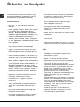
Arýzalar ve çözümler
Ocak bazen çalýþmayabilir ya da çalýþmasý düzgün olmayabilir. Teknik Destek Servisine baþvurmadan önce neler
yapabileceðimize bir bakalým. Öncelikle gaz ve elektrik besleme þebekelerinde kesinti olmadýðýndan emin
olunuz, ve özellikle ocaðýn üzerinde yer alan gaz vanalarýnýn açýk olduðunu kontrol ediniz.
Olasý sebepler / Çözüm:
• Brülörün gaz çýkýþ delikleri týkanmýþ.
• Brülörü oluþturan tüm hareketli parçalar doðru þekilde
monte edilmiþ.
• Ocaðýn yakýnda hava akýmý olabilir.
• Düðmeye tamamen basýlmamýþ olabilir.
• Emniyet donanýmýnýn devreye girmesi için düðme
yeterince basýlý tutulmamýþ olabilir.
• Brülörün emniyet donanýmýnýn karþýsýna gelen gaz çýkýþ
delikleri týkanmýþ.
• Gaz çýkýþ delikleri týkanmýþ.
• Ocaðýn yakýnda hava akýmý olabilir.
• Minimum ayarý doðru yapýlmamýþ.
• Kabýn zemini dümdüz.
• Kap, brülörün ya da elektrikli levhanýn tam ortasýna
oturtulmuþ.
• Izgaralarýn yerleri deðiþmiþ.
Arýzalar
Brülör yanmýyor veya alev düzenli deðil.
Alev emniyet aygýtýna sahip olan
versiyonlarda yanýk kalmýyor.
Brülör minimum pozisyonunda yanýk
kalmýyor.
Kaplar tamamen oturmuyor.
Tüm kontrollere raðmen ocak çalýþmýyor ve tespit etmiþ olduðunuz arýza devam ediyorsa Teknik Destek
Servisi’ni arayýnýz. Bu durumda þu bilgileri veriniz:
• cihazýn modeli (Mod.)
• seri numarasý (S/N)
Bu bilgiler cihazýn ve/veya ambalajýnýn üzerinde yer alan özellikler levhasýnda bulunmaktadýr.
! Yetkili olmayan teknisyenlere asla baþvurmayýnýz ve cihazýnýza orijinal olmayan yedek
parçalarýn takýlmasýný asla kabul etmeyiniz.
INDESIT COMPANY BEYAZ EŞYA PAZARLAMA A.Ş.
Karahasan Sok. No:11 Balmumcu 34349 Beşiktaş/İstanbul
TEL: (+90) 212 355 53 00
FAKS: (+90) 212 212 95 59
WEB: www.hotpoint-a ris ton.com.tr
Cihazýn ömrü 10 yýldýr.
-
 1
1
-
 2
2
-
 3
3
-
 4
4
-
 5
5
-
 6
6
-
 7
7
-
 8
8
-
 9
9
-
 10
10
-
 11
11
-
 12
12
-
 13
13
-
 14
14
-
 15
15
-
 16
16
-
 17
17
-
 18
18
-
 19
19
-
 20
20


Whirlpool PC 640 T X /HA TK Kullanım kılavuzu
- Kategori
- Ocaklar
- Tip
- Kullanım kılavuzu
- Bu kılavuz aynı zamanda aşağıdakiler için de uygundur:
diğer dillerde
İlgili makaleler
Diğer belgeler
-
Indesit TD 641S(BK) IX/HA TR Kullanici rehberi
-
-
-
Indesit PC 640 T X /HA TK Kullanici rehberi
-
-
-
-