Yamaha YST-SW1500 El kitabı
- Kategori
- Enstrüman Amplifikatörü
- Tip
- El kitabı

YAMAHA ELECTRONICS CORPORATION, USA 6660 ORANGETHORPE AVE., BUENA PARK, CALIF. 90620, U.S.A.
YAMAHA CANADA MUSIC LTD. 135 MILNER AVE., SCARBOROUGH, ONTARIO M1S 3R1, CANADA
YAMAHA ELECTRONIK EUROPA G.m.b.H. SIEMENSSTR. 22-34, 25462 RELLINGEN BEI HAMBURG, F.R. OF GERMANY
YAMAHA ELECTRONIQUE FRANCE S.A. RUE AMBROISE CROIZAT BP70 CROISSY-BEAUBOURG 77312 MARNE-LA-VALLEE CEDEX02, FRANCE
YAMAHA ELECTRONICS (UK) LTD. YAMAHA HOUSE, 200 RICKMANSWORTH ROAD WATFORD, HERTS WD1 7JS, ENGLAND
YAMAHA SCANDINAVIA A.B. J A WETTERGRENS GATA 1, BOX 30053, 400 43 VÄSTRA FRÖLUNDA, SWEDEN
YAMAHA MUSIC AUSTRALIA PTY, LTD. 17-33 MARKET ST., SOUTH MELBOURNE, 3205 VIC., AUSTRALIA
Printed in Indonesia
V997110
YST-SW1500
YST-SW1500
Subwoofer System
Enceinte a caisson de grave
OWNER’S MANUAL
MODE D’EMPLOI
BEDIENUNGSANLEITUNG
BRUKSANVISNING
MANUALE DI ISTRUZIONI
MANUAL DE INSTRUCCIONES
GEBRUIKSAANWIJZING
G
SW1500-H14(G)6mm-d 02.9.3, 9:21 AM1

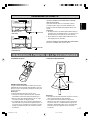
CHECKING THE ACCESSORIES ● Check your package to make sure it contains the following items.
VÉRIFICATION DES ACCESSOIRES
●
Contrôlez le contenu de l’emballage et assurez-vous qu’il contient les accessoires suivants.
ÜBERPRÜFEN DES ZUBEHÖRS ●
Überprüfen Sie den Inhalt der Verpackung, damit sichergestellt ist, daß die folgenden Artikel vorhanden sind.
KONTROLL AV TILLBEHÖREN ● Kontrollera att följande saker finns med i förpackningen.
CONTROLLO DEGLI ACCESSORI ● Controllare che nella confezione siano presenti gli oggetti seguenti.
COMPROBACIÓN DE LOS ACCESORIOS
●
Compruebe el paquete para asegurarse de que tiene los componentes siguientes.
CONTROLEREN VAN DE TOEBEHOREN
● Controleer de doos en kijk of de volgende toebehoren inderdaad aanwezig zijn.
● Remote control
● Télécommande
● Fernbedienung
● Fjärrkontroll
● Telecomando
● Control remoto
● Afstandbediening
● Batteries (size AA, UM-3, R6)
● Piles (format AA, UM-3, R6)
● Batterien (Größe AA, UM-3, R6)
● Batterier (Storl. AA, UM-3, R6)
●
Batterie (dimensioni AA, o
UM-3
, o R6)
● Pilas (tamaño AA, tipo UM-3, R6)
● Batterijen (maat AA, UM-3, R6)
● Grounding cable
● Câble de mise à la masse
● Erdungskabel
● Jordningskabel
● Cavo di massa
● Cable de tierra
● Aardingskabel
● Power cable (U.S.A., Canada, Europe and Korean models only)
● Cordon d’alimentation (Modèles pour les Etats-Unis, le Canada, l’Europe et la Corée seulement)
● Netzkabel (Nur USA, Kanada, Europa und koreanische Modelle)
● Nätkabel (Endast modeller för USA, Kanada, Europa och Korea)
● Cavo d’alimentazione (Solo per i modelli per USA, Canada, Europa e Corea)
● Cable de alimentación (Sólo en modelos para EE.UU., Canadá, Europa y Corea)
● Netsnoer (Alleen modellen voor de U.S.A., Canada, Europa en Korea)
(U.S.A. and Canada models)
(Modèles pour les Etats-Unis et le Canada)
(USA und Kanada Modelle)
(Modeller för USA och Kanada)
(Modelli per USA e Canada)
(Modelos para EE.UU. y Canadá)
(Modellen voor de U.S.A. en Canada)
(Europe and Korean models)
(Modèles pour l’Europe et la Corée)
(Europa und koreanische Modelle)
(Modeller för Europa och Korea)
(Modelli per Europa e Corea)
(Modelos para Europa y Corea)
(Modellen voor Europa en Korea)
1-SW1500_G_pre.p65 2003.02.20, 14:081

English
E-1
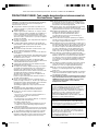
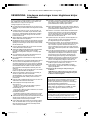
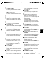
Please read the following operating precautions before use.
YAMAHA will not be held responsible for any damage
and/or injury caused by not following the cautions below.
● To assure the finest performance, please read this
manual carefully. Keep it in a safe place for future
reference.
● Install this unit in a cool, dry, clean place – away from
windows, heat sources, sources of excessive vibration,
dust, moisture and cold. Avoid sources of humming
(transformers, motors). To prevent fire or electrical
shock, do not expose this unit to rain or water.
● Never open the cabinet. If something drops into the set,
contact your dealer.
● The voltage to be used must be the same as that
specified on the rear panel. Using this unit with a higher
voltage than specified is dangerous and may cause a
fire and/or electric shock.
● To reduce the risk or fire or electric shock, do not expose
this unit to rain or moisture.
● Do not use force on switches, controls or connection
wires. When moving the unit, first disconnect the power
plug and the wires connected to other equipment. Never
pull the wires themselves.
● When not planning to use this unit for a long period (i.e.
vacation, etc.), disconnect the AC power plug from the
wall outlet.
● To prevent lightning damage, disconnect the AC power
plug when there is an electric storm.
● Since this unit has a built-in power amplifier, heat will
radiate from the rear panel. Place the unit apart from the
walls, allowing enough spaces above, behind and on
both sides of the unit to prevent fire or damage.
Furthermore, do not position with the rear panel facing
down on the floor or other surfaces.
Be sure to allow spaces of at least 20 cm above, behind
and on both sides of the unit.
● Do not cover the rear panel of this unit with a
newspaper, a tablecloth, a curtain, etc. in order not to
obstruct heat radiation. If the temperature inside the unit
rises, it may cause fire, damage to the unit and/or
personal injury.
●
Do not place small metallic objects on this unit.
Otherwise, the object may fall, possibly causing an injury.
● Do not place the following objects on this unit:
Glass, china, etc.
If glass etc. falls by vibrations and breaks, it may cause
personal injury.
A burning candle etc.
If the candle falls by vibrations, it may cause fire and
personal injury.
A vessel with water in it
If the vessel falls by vibrations and water spills, it may
cause damage to the unit, and/or you may get an
electric shock.
● Do not place this unit where foreign objects such as
water drips might fall. It might cause a fire, damage to
this unit, and/or personal injury.
● Never place a fragile object near the YST port of this
unit. If the object falls or drops by the air pressure, it may
cause damage to the unit and/or personal injury.
● Never put a hand or a foreign object into the YST port
located on the front of this unit. When moving this unit,
do not hold the port as it might cause personal injury
and/or damage to this unit.
● Never open the cabinet. It might cause an electric shock
since this unit uses a high voltage. It might also cause
personal injury and/or damage to this unit.
●
When using a humidifier, be sure to avoid condensation
inside this unit by allowing enough spaces around this unit
or avoiding excess humidification. Condensation might
cause a fire, damage to this unit, and/or electric shock.
● Super-bass frequencies reproduced by this unit may
cause a turntable to generate a howling sound. In such a
case, move this unit away from the turntable.
● This unit may be damaged if certain sounds are
continuously outputted at high volume level. For
example, if 20 Hz–50 Hz sine waves from a test disc,
bass sounds from electronic instruments, etc. are
continuously outputted, or when the stylus of a turntable
touches the surface of a disc, reduce the volume level to
prevent this unit from being damaged.
● If you hear distorted noise (i.e., unnatural, intermittent
“rapping” or “hammering” sounds) coming from this unit,
reduce the volume level. Extremely loud playing of a
movie soundtrack’s low frequency, bass-heavy sounds or
similarly loud popular music passages can damage this
speaker system.
● Vibration generated by super-bass frequencies may
distort images on a TV. In such a case, move this unit
away from the TV set.
● Do not attempt to clean this unit with chemical solvents
as this might damage the finish. Use a clean, dry cloth.
● Be sure to read the “TROUBLESHOOTING” section
regarding common operating errors before concluding
that the unit is faulty.
● Secure placement or installation is the owner’s
responsibility.
YAMAHA shall not be liable for any accident caused
by improper placement or installation of speakers.
Standby mode
When this unit is turned off by pressing the STANDBY/ON
button on the front panel, this unit consumes a small
amount of power. This state is called the standby mode.
This unit’s power supply is completely cut off from the AC
line only when the POWER switch is set in the OFF
position or the AC power cable is disconnected.
This unit features a magnetically shielded design, but
there is still a chance that placing it too close to a TV set
might impair picture color. Should this happen, move this
unit away from the TV set.
FOR CANADIAN CUSTOMERS
To prevent electric shock, match wide blade of plug to
wide slot and fully insert.
This Class B digital apparatus complies with Canadian
ICES-003.
CAUTION: Read this before operating your unit.
Thank you for selecting this YAMAHA Subwoofer System.
2-SW1500(E) (02.9.2)a 02.9.3, 9:29 AM1

E-2
CONTENTS
CHECKING THE ACCESSORIES
.....................................
Inside of Front Cover
CAUTION .................................................. 1
FEATURES ............................................... 2
PLACEMENT ............................................ 3
CONNECTIONS....................................... 4
Connecting to line output (pin jack)
terminals of the amplifier ....................... 4
Connecting to speaker output terminals
of the amplifier ....................................... 6
Connecting to H.P.F. OUTPUT terminals
............................................................... 8
Ground connection ............................... 10
Connecting the AC power cable ........... 11
NOTES ABOUT THE REMOTE
CONTROL ............................................. 11
CONTROLS AND THEIR
FUNCTIONS .......................................... 12
AUTOMATIC POWER-SWITCHING
FUNCTION............................................. 14
ADJUSTING THE SUBWOOFER
BEFORE USE ........................................ 15
Storing preset data of the VOLUME
control etc. ............................................ 16
Frequency characteristics.................... 17
ADVANCED YAMAHA ACTIVE
SERVO TECHNOLOGY ......................... 18
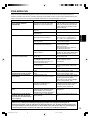
TROUBLESHOOTING ............................19
SPECIFICATIONS ................................. 20
FEATURES
● This subwoofer system employs Advanced
YAMAHA Active Servo Technology which YAMAHA
has developed for reproducing higher quality
super-bass sound. (Refer to page 18 for details on
Advanced YAMAHA Active Servo Technology.) This
super-bass sound adds a more realistic, theater-in-
the-home effect to your stereo system.
● This subwoofer can be easily added to your
existing audio system by connecting to either the
speaker terminals or the line output (pin jack)
terminals of the amplifier.
● For the effective use of the subwoofer, the
subwoofer’s super-bass sound should be matched
to the sounds of your main speakers. You can
create the best sound quality for various listening
conditions by using the HIGH CUT control and the
PHASE button.
● You can make setting changes and adjustments for
the subwoofer by using the remote control without
moving from your listening position.
● The Automatic power-switching function saves you
the trouble of pressing the STANDBY/ON button to
turn the power on and off.
● You can select bass effect suitable for the source
by using the B.A.S.S. button.
● The use of the H.P.F. OUTPUT terminals for
connecting with the amplifier is effective for
improving sound quality of your speaker system.
This connection prevents sound output from the
main speakers from muddying by filtering out low
frequencies of input signals to be sent to the main
speakers which are not suitable for reproducing
low frequencies.
QD-Bass Technology
QD-Bass (Quatre Dispersion Bass) technology uses
square, pyramid-shaped reflective plates to radiate the
sound in four horizontal directions.
2-SW1500(E) (02.9.2)a 02.9.3, 9:29 AM2

English
E-3
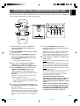
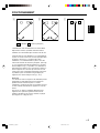
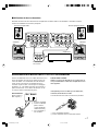
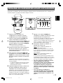
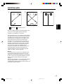
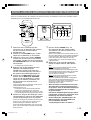
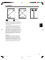
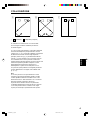
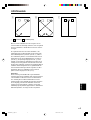
PLACEMENT
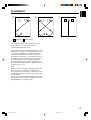
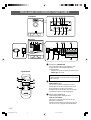
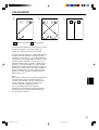
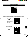
One subwoofer will have a good effect on your audio
system, however, the use of two subwoofers is
recommended to obtain more effect.
If using one subwoofer, it is recommended to place it on the
outside of either the right or the left main speaker. (See fig.
Å.) If using two subwoofers, it is recommended to place
them on the outside of each main speaker. (See fig. ı.)
The placement shown in fig. Ç is also possible, however, if
the subwoofer system is placed directly facing the wall, the
bass effect may die because the sound from it and the
sound reflected by the wall may cancel out each other. To
prevent this from happening, face the subwoofer system at
an angle as in fig. Å or ı.
Note
There may be a case that you cannot obtain enough super-
bass sounds from the subwoofer when listening in the
center of the room. This is because “standing waves” have
been developed between two parallel walls and they cancel
the bass sounds.
In such a case, face the subwoofer obliquely to the wall. It
also may be necessary to break up the parallel surfaces by
placing bookshelves etc. along the walls.
( : subwoofer, : main speaker)
Çı
Å
2-SW1500_G_E.p65 2003.02.20, 11:503

E-4
OUTPUT
TO SPEAKERS
INPUT
1
FROM AMPLIFIER
100Hz80Hz
/MONO
NORMAL
INPUT
2
INPUT
3
LFE
GND
H.P.F.OUTPUT
SPLIT SUBWOOFER
SUBWOOFER
(LOW PASS)
AC IN
ON
POWER
OFF
HIGH
LOW
OFF
AUTO
STANDBY
OUTPUT
INPUT
REMOTE
OUTPUT
TO SPEAKERS
INPUT
1
FROM AMPLIFIER
100Hz80Hz
/MONO
NORMAL
INPUT
2
INPUT
3
LFE
GND
H.P.F.OUTPUT
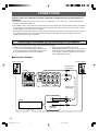
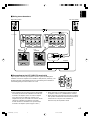
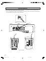
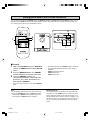
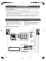
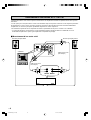
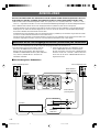
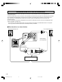
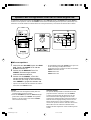
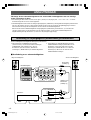
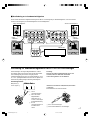
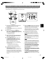
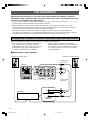
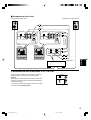
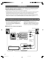
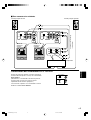
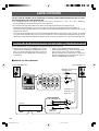
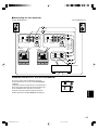
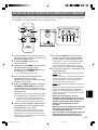
CONNECTIONS
Caution: Plug in the subwoofer and other audio/video components after all connections are
completed.
● All connections must be correct, that is to say L (left) to L, R (right) to R, “+” to “+” and “–” to “–”. Also refer to the owner’s
manual for each of your components.
● The subwoofer can be connected to either the line output (pin jack) terminals or the speaker output terminals of the amplifier.
Choose one of the ways shown in this section that is more suitable for your audio system. Also, refer to the owner’s manual
of your component to be connected to the subwoofer.
Basically, connect the subwoofer to the line output (pin jack) terminal(s) of the amplifier. (Refer to pages 4 and 5 for details.)
If your amplifier does not have any line output terminal, connect the subwoofer to the speaker output terminals of the
amplifier. (Refer to pages 6 and 7 for details.)
Subwoofer
Amplifier
● To connect with a YAMAHA DSP amplifier (or AV
receiver), connect the SUBWOOFER (or LOW PASS etc.)
terminal on the rear of the DSP amplifier (or AV receiver)
to the L/MONO INPUT2 terminal of the subwoofer.
Connect the main speakers to the speaker output terminals of the amplifier.
● When connecting the subwoofer to the SPLIT
SUBWOOFER terminals on the rear of the DSP amplifier,
be sure to connect the L/MONO INPUT2 terminal to the
“L” side and the R INPUT2 terminal to the “R” side of the
SPLIT SUBWOOFER terminals.
Audio pin cable
(not included)
Connecting to line output (pin jack) terminals of the amplifier
Using one subwoofer
Left main speaker
Right main speaker
Mono pin cable
(not included)
2-SW1500(E) (02.9.2)a 02.9.3, 9:29 AM4

English
E-5
AC IN
ON
POWER
OFF
HIGH
LOW
OFF
AUTO
STANDBY
OUTPUT
INPUT
REMOTE
OUTPUT
TO SPEAKERS
INPUT
1
FROM AMPLIFIER
100Hz80Hz
/MONO
NORMAL
INPUT
2
INPUT
3
LFE
GND
H.P.F.OUTPUT
AC IN
ON
POWER
OFF
HIGH
LOW
OFF
AUTO
STANDBY
OUTPUT
INPUT
REMOTE
OUTPUT
TO SPEAKERS
INPUT
1
FROM AMPLIFIER
100Hz80Hz
/MONO
NORMAL
INPUT
2
INPUT
3
LFE
GND
H.P.F.OUTPUT
OUTPUT
TO SPEAKERS
INPUT
1
FROM AMPLIFIER
100Hz80Hz
/MONO
NORMAL
INPUT
2
INPUT
3
LFE
GND
H.P.F.OUTPUT
SPLIT SUBWOOFER
OUTPUT
TO SPEAKERS
INPUT
1
FROM AMPLIFIER
100Hz80Hz
/MONO
NORMAL
INPUT
2
INPUT
3
LFE
GND
H.P.F.OUTPUT
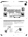
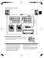
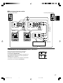
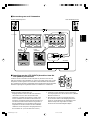
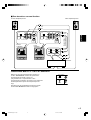
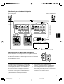
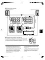
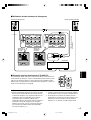
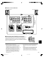
Using two subwoofers
Notes
● Some amplifiers have line output terminals labelled PRE
OUT. When you connect the subwoofer to the PRE OUT
terminals of the amplifier, make sure that the amplifier
has at least two sets of PRE OUT terminals. If the
amplifier has only one set of PRE OUT terminals, do not
connect the subwoofer to the PRE OUT terminals.
Instead, connect the subwoofer to the speaker output
terminals of the amplifier. (Refer to pages 6 and 7.)
● When connecting to a monaural line output terminal of
the amplifier, connect the L/MONO INPUT2 terminal.
● When connecting to line output terminals of the amplifier,
other speakers should not be connected to the OUTPUT
terminals on the rear panel of the subwoofer. If
connected, they will not produce sound.
Right
subwoofer
Amplifier
Mono pin cables
(not included)
Left main speaker
Right main speaker
Left
subwoofer
Connecting to the LFE (INPUT3) terminal(s)
If your amplifier can cut off high frequencies from the signals for sending to the
subwoofer, connect the amplifier to the subwoofer’s LFE (INPUT3) terminal(s). This
will bring you higher sound quality because the signal routing in the subwoofer is
shortened bypassing the built-in HIGH CUT circuit.
F
/MONO
NORMAL
INPUT
2
INPUT
3
LFE
2-SW1500(E) (02.9.2)a 02.9.3, 9:29 AM5

E-6
AC IN
ON
POWER
OFF
HIGH
LOW
OFF
AUTO
STANDBY
OUTPUT
INPUT
REMOTE
OUTPUT
TO SPEAKERS
INPUT
1
FROM AMPLIFIER
100Hz80Hz
/MONO
NORMAL
INPUT
2
INPUT
3
LFE
GND
H.P.F.OUTPUT
OUTPUT
TO SPEAKERS
INPUT
1
FROM AMPLIFIER
100Hz80Hz
/MONO
NORMAL
INPUT
2
INPUT
3
LFE
GND
H.P.F.OUTPUT
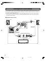
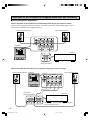
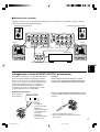
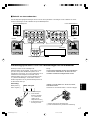
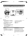
Connecting to speaker output terminals of the amplifier
Using one subwoofer
If your amplifier has only one set of main speaker output terminals
Connect the speaker output terminals of the amplifier to the INPUT1 terminals of the subwoofer, and connect the OUTPUT
terminals of the subwoofer to the main speakers.
Left main speakerRight main speaker
Subwoofer
Amplifier
Speaker output
terminals
If your amplifier has two sets of speaker output terminals
AB
OUTPUT
TO SPEAKERS
INPUT
1
FROM AMPLIFIER
100Hz80Hz
/MONO
NORMAL
INPUT
2
INPUT
3
LFE
GND
H.P.F.OUTPUT
AC IN
ON
POWER
OFF
HIGH
LOW
OFF
AUTO
STANDBY
OUTPUT
INPUT
REMOTE
OUTPUT
TO SPEAKERS
INPUT
1
FROM AMPLIFIER
100Hz80Hz
/MONO
NORMAL
INPUT
2
INPUT
3
LFE
GND
H.P.F.OUTPUT
Left main speaker
Right main speaker
Speaker output
terminals
Subwoofer
Amplifier
(Both A and B speaker outputs must be ON.)
2-SW1500(E) (02.9.2)a 02.9.3, 9:29 AM6

English
E-7
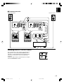
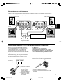
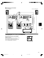
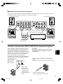
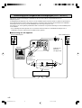
Using two subwoofers
Connect the speaker output terminals of the amplifier to the INPUT1 terminals of the subwoofer, and connect the OUTPUT
terminals of the subwoofer to the main speakers.
AC IN
ON
POWER
OFF
HIGH
LOW
OFF
AUTO
STANDBY
OUTPUT
INPUT
REMOTE
OUTPUT
TO SPEAKERS
INPUT
1
FROM AMPLIFIER
100Hz80Hz
/MONO
NORMAL
INPUT
2
INPUT
3
LFE
GND
H.P.F.OUTPUT
AC IN
ON
POWER
OFF
HIGH
LOW
OFF
AUTO
STANDBY
OUTPUT
INPUT
REMOTE
OUTPUT
TO SPEAKERS
INPUT
1
FROM AMPLIFIER
100Hz80Hz
/MONO
NORMAL
INPUT
2
INPUT
3
LFE
GND
H.P.F.OUTPUT
OUTPUT
TO SPEAKERS
INPUT
1
FROM AMPLIFIER
100Hz80Hz
/MONO
NORMAL
INPUT
2
INPUT
3
LFE
GND
H.P.F.OUTPUT
OUTPUT
TO SPEAKERS
INPUT
1
FROM AMPLIFIER
100Hz80Hz
/MONO
NORMAL
INPUT
2
INPUT
3
LFE
GND
H.P.F.OUTPUT
Left main speakerRight main speaker
Amplifier
Speaker output terminals
Caution
Do not let the bare speaker wires touch each other as
this could damage the subwoofer or the amplifier, or
both of them.
<U.S.A., Canada, Australia and Korean models only>
Banana Plug connections are also possible.
1Tighten the terminal knob.
2Simply insert the Banana Plug connector into the
terminal.
Connecting to the INPUT1/OUTPUT terminals of the subwoofer
For connections, keep the speaker cables as short as
possible. Do not bundle or roll up the excess part of the
cables. If the connections are faulty, no sound will be heard
from the subwoofer or the speakers, or both of them. Make
sure that the + and – polarity markings of the speaker
cables are observed and set correctly. If these cables are
reversed, the sound will be unnatural and lack bass.
How to Connect:
Red: positive (+)
Black: negative (–)
1 Loosen the knob.
2 Insert the bare wire.
[Remove approx.
10 mm (3/8”)
insulation from the
speaker wires.]
3 Tighten the knob and
secure the wire.
1
2
3
1
2
Right
subwoofer
Left
subwoofer
2-SW1500(E) (02.9.2)a 02.9.3, 9:29 AM7

E-8
MAIN INPRE OUT
AC IN
ON
POWER
OFF
HIGH
LOW
OFF
AUTO
STANDBY
OUTPUT
INPUT
REMOTE
OUTPUT
TO SPEAKERS
INPUT
1
FROM AMPLIFIER
100Hz80Hz
/MONO
NORMAL
INPUT
2
INPUT
3
LFE
GND
H.P.F.OUTPUT
OUTPUT
TO SPEAKERS
INPUT
1
FROM AMPLIFIER
100Hz80Hz
/MONO
NORMAL
INPUT
2
INPUT
3
LFE
GND
H.P.F.OUTPUT
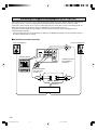
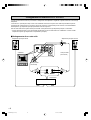
Connecting to H.P.F. OUTPUT terminals
The use of the H.P.F. OUTPUT terminals for connections with the amplifier will improve sound quality of your speaker system.
The H.P.F. (High-Pass Filter) OUTPUT terminals of the subwoofer cut off frequencies below the selected frequency point from
the input signals, and output high frequencies only. By connecting this terminal with the MAIN IN terminals of the amplifier, the
main speakers reproduce high frequencies only.
This will make the whole sound quality clear by preventing sound muddying between the main speakers and the subwoofer.
* This connection can be made if your amplifier has PRE OUT and MAIN IN terminals or you are using separate amplifiers
(pre-amplifier and main amplifier).
To connect one unit only
Left main speaker
Right main speaker
Audio pin cable
(not included)
Amplifier
Subwoofer
Audio pin cable
(not included)
2-SW1500(E) (02.9.2)a 02.9.3, 9:29 AM8

English
E-9
MAIN INPRE OUT
AC IN
ON
POWER
OFF
HIGH
LOW
OFF
AUTO
STANDBY
OUTPUT
INPUT
REMOTE
OUTPUT
TO SPEAKERS
INPUT
1
FROM AMPLIFIER
100Hz80Hz
/MONO
NORMAL
INPUT
2
INPUT
3
LFE
GND
H.P.F.OUTPUT
AC IN
ON
POWER
OFF
HIGH
LOW
OFF
AUTO
STANDBY
OUTPUT
INPUT
REMOTE
OUTPUT
TO SPEAKERS
INPUT
1
FROM AMPLIFIER
100Hz80Hz
/MONO
NORMAL
INPUT
2
INPUT
3
LFE
GND
H.P.F.OUTPUT
OUTPUT
TO SPEAKERS
INPUT
1
FROM AMPLIFIER
100Hz80Hz
/MONO
NORMAL
INPUT
2
INPUT
3
LFE
GND
H.P.F.OUTPUT
OUTPUT
TO SPEAKERS
INPUT
1
FROM AMPLIFIER
100Hz80Hz
/MONO
NORMAL
INPUT
2
INPUT
3
LFE
GND
H.P.F.OUTPUT
To connect two units
After the connection is made, select the desired frequency
point (80 Hz or 100 Hz) with the H.P.F. OUTPUT switch.
(Normally, it is recommended to select the frequency point
nearer to the main speakers’ minimum reproduceable
frequency.)
Frequencies higher than the selected frequency are output
from the H.P.F. OUTPUT terminals.
Switching the H.P.F. OUTPUT switch
100Hz80Hz
GND
H.P.F.OUTPUT
Right main speaker
Amplifier
Mono pin cables
(not included)
Right
subwoofer
Left
subwoofer
Left main speaker
2-SW1500(E) (02.9.2)a 02.9.3, 9:29 AM9

E-10
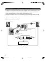
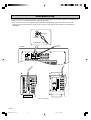
Ground connection
AC IN
ON
POWER
OFF
HIGH
LOW
OFF
AUTO
STANDBY
OUTPUT
INPUT
REMOTE
OUTPUT
TO SPEAKERS
INPUT
1
FROM AMPLIFIER
100Hz80Hz
/MONO
NORMAL
INPUT
2
INPUT
3
LFE
GND
H.P.F.OUTPUT
DIGITAL OUTPUT AUDIO
DIGITAL INPUT 6CH INPUT
MD/
TAPE
CD-R
CD-R
CD
DVD
SIGNAL
GND
D-TV
/LD
OPTICAL
OPTICAL
COAXIAL
CD
IN
(PLAY)
R
MD/TAPE
CBL
/SAT
OUT
(REC)
CD
PHONO
MAIN
CENTER
SUB
WOOFER
SURROUND
IN
(PLAY)
CD-R
OUT
(REC)
L R
RS-
232C
COAXIAL:
SELECT BY SETMENU
LD
RF
(AC-3)
PRE
OUT
MAIN
IN
AUDIO SIGNAL
TUNER
PHONO
CD/DVD
IN
(PLAY)
IN
(PLAY)
TAP E
OUT
(REC)
OUT
(REC)
MD
AUX
R L
2
3
4
4
1
3
R L
R L
Tighten
Insert
Subwoofer
Metal part
If there is a humming noise when using the subwoofer connected to the speaker terminals, connect the subwoofer and the
receiver/amplifier with the grounding cable as shown in Illustration A.
* If there is no ground terminal (GND) on the receiver/amplifier side, connect the cable to a screw that fastens the top cover of
the receiver/amplifier to the rear panel as shown in Illustration B.
Receiver/amplifier
Grounding cable
2-SW1500(E) (02.9.2)a 02.9.3, 9:29 AM10

English
E-11
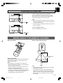
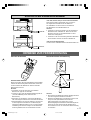
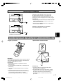
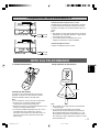
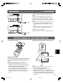
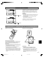
Battery replacement
If you find that the remote control must be used closer to
the main unit, the batteries are weak. Replace both
batteries with new ones.
Notes
● Use only AA, R6, UM-3 batteries for replacement.
● Be sure the polarities are correct. (See the illustration
inside the battery compartment.)
● Remove the batteries if the remote control will not be
used for an extended period of time.
● If batteries leak, dispose of them immediately. Avoid
touching the leaked material or letting it come in contact
with clothing, etc. Clean the battery compartment
thoroughly before installing new batteries.
Notes
● There should be no large obstacles between the remote
control and the main unit.
● If the remote control sensor is directly illuminated by
strong lighting (especially an inverter type of fluorescent
lamp etc.), it might cause the remote control not to work
correctly. In this case, reposition the main unit to avoid
direct lighting.
3
1
2
Battery installation
Remote control operation range
30°
30°
Remote control
sensor
Within approximately
6 m (20 feet)
NOTES ABOUT THE REMOTE CONTROL
Connecting the AC power cable
<U.S.A., Canada, Europe and Korean models>
When all connections are completed, plug the included
power cable into the AC IN socket of the subwoofer, and
then plug in the power cable to the wall outlet.
Notes
● Never connect any power cable other than the included
one to the subwoofer. Otherwise, it may result in causing
fire or an electrical shock.
● Do not connect the included power cable to any other unit
than this subwoofer.
<U.K. and Australia models>
Plug in the subwoofer to the wall outlet.
AC IN
ON
POWER
OFF
AC IN
ON
POWER
OFF
(U.S.A. model)
(U.K. model)
To AC outlet
To AC outlet
2-SW1500(E) (02.9.2)a 02.9.3, 9:29 AM11

E-12
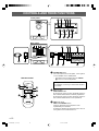
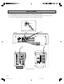
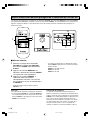
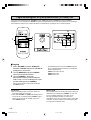
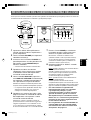
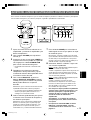
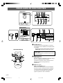
1 STANDBY/ON button
Press this button to turn on the power. Press again to
set the subwoofer in the standby mode.
* This button can be used only when the POWER
(A) switch is set in the ON position.
Standby mode
The subwoofer is still using a small amount of power
in this mode.
2 B.A.S.S. switch
MUSIC/MOVIE button
By pressing this switch to select the MOVIE mode, the
bass sound in video software is faithfully reproduced.
By pressing this switch to select the MUSIC mode, the
bass sound in audio software is well reproduced.
3 HIGH CUT control
HIGH CUT UP/DOWN buttons
Select the upper limit of the frequencies to be
reproduced by the subwoofer.
To adjust the control on the front panel, put a coin, etc.
in the groove on the control and turn it.
CONTROLS AND THEIR FUNCTIONS
AC IN
ON
POWER
OFF
HIGH
LOW
OFF
AUTO
STANDBY
OUTPUT
INPUT
REMOTE
OUTPUT
TO SPEAKERS
INPUT
1
FROM AMPLIFIER
100Hz80Hz
/MONO
NORMAL
INPUT
2
INPUT
3
LFE
GND
H.P.F.OUTPUT
SUBWOOFER SYSTEM YST-SW1500
MUSIC/MOVIE PHASE
VOLUMEHIGH CUTB.A.S.S.STANDBY/ON
1
1014Hz40Hz 0
PRESET
2
3
SUBWOOFER SYSTEM YST-SW1500
MUSIC/MOVIE PHASE
VOLUMEHIGH CUTB.A.S.S.STANDBY/ON
1
10140Hz40Hz 0
PRESET
2
3
HIGH
LOW
OFF
AUTO
STANDBY
OUTPUT
INPUT
REMOTE
OUTPUT
TO SPEAKERS
INPUT
1
FROM AMPLIFIER
100Hz80Hz
/MONO
NORMAL
INPUT
2
INPUT
3
LFE
GND
H.P.F.OUTPUT
AC IN
ON
POWER
OFF
5789
2
t
o
yu i
re
4
6
13
q0
w
Rear panel
Front panel
p2
1
a
4
3
Remote control
2-SW1500(E) (02.9.2)a 02.9.3, 9:29 AM12

English
E-13
4
VOLUME control
VOLUME UP/DOWN buttons
Adjust the volume level. Turn the control clockwise or
press the UP button to increase the volume.
Turn the control counterclockwise or press the DOWN
button to decrease the volume.
To adjust the control on the front panel, put a coin, etc.
in the groove on the control and turn it.
5 Remote control sensor
Receives signals from the remote control.
6 Power indicator (LED)
Lights up in green while the subwoofer is turned on.
Lights up in red when the subwoofer is turned into the
standby mode by the automatic power-switching
function.
7 MUSIC/MOVIE indicator (LED)
Lights up in red when the MUSIC mode is selected,
and in green when the MOVIE mode is selected.
8 PHASE indicator (LED)
Lights up in red when the PHASE button (J) is set in
the regular mode, and in green when it is set in the
reverse mode.
9 PRESET 1/2/3 indicators (LED)
Show which PRESET number (1, 2 or 3) is selected.
(If the subwoofer is turned into the standby mode when
one of these indicators are illuminated, no indicator will
light up next time the subwoofer is turned on.)
0 AC IN
<U.S.A., Canada, Europe and Korean models only>
Plug the included power cable into this socket. Never
connect a power cable other than the included one to
this socket. Also, never connect the included power
cable to another unit.
A POWER switch
Normally, set this switch to the ON position to use the
subwoofer. In this state, you can turn on the subwoofer
or turn the subwoofer into the standby mode by
pressing the STANDBY/ON (1) button. Set this switch
to the OFF position to completely cut off the
subwoofer’s power supply from the AC line.
B REMOTE terminals
These terminals are used for custom installation
system. When the subwoofer is connected to the
components for custom installation system, you can
operate the subwoofer with the system remote control.
C AUTO STANDBY (HIGH/LOW/OFF) switch
This switch is originally set to the OFF position. By
setting this switch to the HIGH or LOW position, the
subwoofer’s automatic power-switching function
operates as described on page 14. If you do not need
this function, leave this switch in the OFF position.
D GND terminal
Connecting this terminal to ground (GND) terminal of
the receiver/amplifier can reduce a humming noise.
(See page 10.)
E H.P.F. (High Pass Filter) OUTPUT switch
Selects the upper limit of the frequencies to be cut off
from the signals outputted at the H.P.F. OUTPUT
terminals. Use this switch only when the H.P.F.
OUTPUT terminals are used for connecting with the
amplifier. (See page 8 for details)
H.P.F. OUTPUT terminals
These terminals cut off frequencies below the
frequency point selected by the H.P.F. OUTPUT switch
from the input signals and output higher frequencies.
F INPUT3 (LFE) terminals
The HIGH CUT control (3) has no effect on the signals
inputted to these terminals. (See page 5 for details)
G INPUT2 terminals
Used to input line level signals from the amplifier.
(Refer to “CONNECTIONS” for details.)
H OUTPUT (TO SPEAKERS) terminals
Can be used for connecting to the main speakers.
Signals are sent directly from the amplifier to the main
speakers by way of these terminals.
(Refer to “CONNECTIONS” for details.)
I INPUT1 (FROM AMPLIFIER) terminals
Used to connect the subwoofer with the speaker
terminals of the amplifier.
(Refer to “CONNECTIONS” for details.)
J PHASE button
Normally press this button to select the reverse mode.
However, according to your speaker systems or the
listening condition, there may be a case when better
sound quality is obtained by selecting the regular
mode. Select the better mode by monitoring the sound.
In the reverse mode, the PHASE indicator on the front
panel lights up in green, and in the regular mode, it
lights up in red.
K MEMORY button/PRESET buttons
Used to store and recall the data for the B.A.S.S.
[MUSIC/MOVIE] (2), the VOLUME [VOLUME UP/
DOWN] (4), the HIGH CUT [HIGH CUT UP/DOWN]
(3) and the PHASE (J) adjustments. (See page 16.)
2-SW1500(E) (02.9.2)a 02.9.3, 9:29 AM13

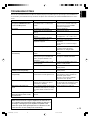
E-14
If the source being played is stopped and the input signal is
cut off for 7 to 8 minutes, the subwoofer automatically
switches to the standby mode. (When the subwoofer
switches to the standby mode by the automatic power-
switching function, the power indicator lights up in red.)
When you play a source again, the power of the subwoofer
turns on automatically by sensing audio signals input to the
subwoofer.
This function operates by sensing a certain level of low
frequency input signal. Usually set the AUTO STANDBY
switch to the LOW position. However, if the power is not
switched to ON or STANDBY smoothly, set the switch to the
HIGH position. In the HIGH position, the power will turn on
even with a low level of input signal. But please be aware
that the subwoofer may not switch to the standby mode
when there is an extremely low input signal.
* The power might turn on unexpectedly by sensing noise
from other appliances. If that occurs, set the AUTO
STANDBY switch to the OFF position.
* This function detects the low-frequency components
below 200 Hz of the input signals (i.e., the explosion in
the action movie, the sound of the bass guitar or the bass
drum, etc.).
* The minutes required to switch the subwoofer to the
standby mode might change by sensing noise from other
appliances.
This function is available only when the power of the
subwoofer is on (by setting the STANDBY/ON button to
“ON”).
This function will not work if the subwoofer is turned
into the standby mode by using the STANDBY/ON
button. (The power indicator on the front panel goes
off.)
AUTOMATIC POWER-SWITCHING FUNCTION
2-SW1500(E) (02.9.2)a 02.9.3, 9:29 AM14

English
E-15
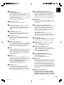
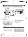
1 Set the volume level on the amplifier to
minimum, and turn on the amplifier and
other components.
2 Turn the VOLUME control to set the control
to minimum (0).
3 Make sure that the POWER switch on the
rear panel is set to the ON position, then
press the STANDBY/ON button to turn on
the subwoofer.
* The power indicator lights up in green.
4 Play a source containing low-frequency
components and adjust the amplifier’s
volume control to the desired listening level.
5 Turn the HIGH CUT control (or press the
HIGH CUT UP/DOWN buttons on the
remote control) to set the control to the
position where the desired response can be
obtained.
Normally, set the control to the main speaker’s rated
minimum reproducible frequency*.
* The main speaker’s rated minimum reproducible
frequency can be looked up in the speakers’ catalog
or owner’s manual.
6 Increase the volume gradually to adjust the
volume balance between the subwoofer and
the main speakers.
Normally, set the control to the level where you can
obtain a little more bass effect than when the subwoofer
is not used. If the desired response cannot be obtained,
adjust the HIGH CUT control and the VOLUME control
again.
Before using the subwoofer, adjust the subwoofer to obtain the optimum volume and tone balance between the subwoofer and
the main speakers by following the procedures described below.
7 Press the PHASE button to select the
regular or reverse mode which gives you the
better bass sound.
Normally, select the reverse mode (so that the PHASE
indicator on the front panel lights up in green). If the
desired response cannot be obtained, select the regular
mode (so that the PHASE indicator lights up in red).
8 Select “MOVIE” or “MUSIC” according to the
played source.
MOVIE (when the MUSIC/MOVIE indicator on the front
panel lights up in green):
When a movie type source is played, the low-frequency
effects are enhanced to allow the listener enjoy more
powerful sound. (The sound will be thicker and deeper.)
MUSIC (when the MUSIC/MOVIE indicator on the front
panel lights up in red):
When an ordinary music source is played, the excessive
low-frequency components are cut off to make the
sound clearer. (The sound will be lighter and repro-
duces the melody line more clearly.)
• Once the volume balance between the
subwoofer and the main speakers is adjusted,
you can adjust the volume of your whole
sound system by using the amplifier’s volume
control.
However, if you change the main speakers to
others, you must make this adjustment again.
• For adjusting the VOLUME control, the HIGH
CUT control and the PHASE button, refer to
“Frequency characteristics” on page 17.
ADJUSTING THE SUBWOOFER BEFORE USE
SUBWOOFER SYSTEM YST-SW1500
MUSIC/MOVIE PHASE
VOLUMEHIGH CUTB.A.S.S.STANDBY/ON
1
1014Hz40Hz 0
PRESET
2
3
SUBWOOFER SYSTEM YST-SW1500
MUSIC/MOVIE PHASE
VOLUMEHIGH CUTB.A.S.S.STANDBY/ON
1
10140Hz40Hz 0
PRESET
2
3
2, 6
6
5
3
8
7
53 8
2-SW1500(E) (02.9.2)a 02.9.3, 9:30 AM15

E-16
Storing preset data of the VOLUME control etc.
You can store preset data of the VOLUME control, the HIGH CUT control, the PHASE button and the B.A.S.S. switch as a set.
Each of the three PRESET buttons on the remote control is used to store (and recall) one set of data. With this function, you
can recall any preset data easily according to the source.
To store
1 Adjust the VOLUME control, the HIGH CUT
control, the PHASE button and the B.A.S.S.
switch.
2 Press the MEMORY button. The PRESET
number indicators on the front panel flash.
3 Press the PRESET 1 button. The
corresponding PRESET number indicator
illuminates. This shows that the data has
been stored in PRESET 1.
* In the same way, store other sets of data in PRESET 2
and 3.
Notes
● A new setting can be stored in place of the former one.
● While the VOLUME control or the HIGH CUT control is
rotating from a PRESET button having been pressed,
pressing another PRESET button is ineffective.
Memory back-up
The memory back-up circuit prevents the stored data from
being lost even if the POWER switch is set off or the power
plug is disconnected from the AC outlet or the power is cut
due to temporary power failure. If, however, the power is lost
for more than one week, the memory may be erased. If so, it
can be re-stored by simply following the steps described
above.
SUBWOOFER SYSTEM YST-SW1500
MUSIC/MOVIE PHASE
VOLUMEHIGH CUTB.A.S.S.STANDBY/ON
1
1014Hz40Hz 0
PRESET
2
3
SUBWOOFER SYSTEM YST-SW1500
MUSIC/MOVIE PHASE
VOLUMEHIGH CUTB.A.S.S.STANDBY/ON
1
10140Hz40Hz 0
PRESET
2
3
1
3
1
2
3
* The default setting of each PRESET button is suitable for
using the following Yamaha speaker system with this
subwoofer.
PRESET 1: NS-8HX, NS-6HX
PRESET 2: NS-4HX
PRESET 3: NS-2HX
2-SW1500(E) (02.9.2)a 02.9.3, 9:30 AM16

English
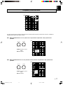
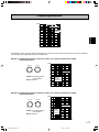
E-17
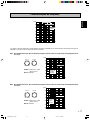
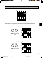
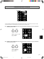
This subwoofer’s frequency characteristics
EX.1 When combined with a 4” or 5” (10 cm or 13 cm) acoustic suspension, 2 way system main
speakers
EX.2 When combined with an 8” or 10” (20 cm or 25 cm) acoustic suspension, 2 way system main
speakers
PHASE–Set to the reverse
mode.
B.A.S.S.–MOVIE
The figures below show the optimum adjustment of each control and the frequency characteristics when this subwoofer is
combined with a typical main speaker system.
PHASE–Set to the reverse
mode.
B.A.S.S.–MOVIE
20 50 100 200 500 Hz
40
50
60
70
80
90
100 dB
HIGH CUT 40 Hz
HIGH CUT 90 Hz
HIGH CUT
140 Hz
20 50 100 200 500 Hz
40
50
60
70
80
90
100 dB
20 50 100 200 500 Hz
40
50
60
70
80
90
100 dB
Main
speaker’s
response
Main
speaker’s
response
YST-SW1500
YST-SW1500
HIGH CUT
140Hz40Hz
VOLUME
100
HIGH CUT
140Hz40Hz
VOLUME
100
Frequency characteristics
2-SW1500(E) (02.9.2)a 02.10.3, 1:36 PM17

E-18
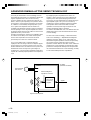
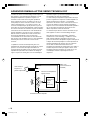
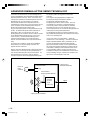
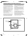
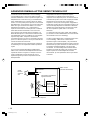
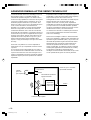
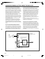
ADVANCED YAMAHA ACTIVE SERVO TECHNOLOGY
The theory of Yamaha Active Servo Technology has been
based upon two major factors, the Helmholtz resonator and
negative-impedance drive. Active Servo Processing
speakers reproduce the bass frequencies through an “air
woofer”, which is a port or opening in the speaker’s cabinet.
This opening is used instead of, and performs the functions
of, a woofer in a conventionally designed speaker system.
Thus, signals of low amplitude within the cabinet can,
according to the Helmholtz resonance theory, be outputted
from this opening as waves of great amplitude if the size of
the opening and the volume of the cabinet are in the correct
proportion to satisfy a certain ratio.
In order to accomplish this, moreover, the amplitudes within
the cabinet must be both precise and of sufficient power
because these amplitudes must overcome the “load”
presented by the air that exists within the cabinet.
Thus it is this problem that is resolved through the
employment of a new design in which the amplifier supplies
special signals. If the electrical resistance of the voice coil
could be reduced to zero, the movement of the speaker unit
would become linear with respect to signal voltage. To
accomplish this, a special negative-impedance output-drive
amplifier for subtracting output impedance of the amplifier is
used.
By employing negative-impedance drive circuits, the
amplifier is able to generate precise, low-amplitude, low-
frequency waves with superior damping characteristics.
These waves are then radiated from the cabinet opening as
high-amplitude signals. The system can, therefore, by
employing the negative-impedance output drive amplifier
and a speaker cabinet with the Helmholtz resonator,
reproduce an extremely wide range of frequencies with
amazing sound quality and less distortion.
The features described above, then, are combined to be the
fundamental structure of the conventional Yamaha Active
Servo Technology.
Our new Active Servo Technology — Advanced Yamaha
Active Servo Technology — adopted Advanced Negative
Impedance Converter (ANIC) circuits, which allows the
conventional negative impedance converter to dynamically
vary in order to select an optimum value for speaker
impedance variation. With this new ANIC circuits, Advanced
Yamaha Active Servo Technology can provide more stable
performance and improved sound pressure compared with
the conventional Yamaha Active Servo Technology, resulting
in more natural and dynamic bass reproduction.
High-amplitude
bass sound
Cabinet
Port
Air woofer
(Helmholtz resonator)
Signals of low amplitude
Advanced Negative-
impedance Converter
Active Servo
Processing
Amplifier
Signals
2-SW1500(E) (02.9.2)a 02.9.3, 9:30 AM18
Sayfa yükleniyor...
Sayfa yükleniyor...
Sayfa yükleniyor...
Sayfa yükleniyor...
Sayfa yükleniyor...
Sayfa yükleniyor...
Sayfa yükleniyor...
Sayfa yükleniyor...
Sayfa yükleniyor...
Sayfa yükleniyor...
Sayfa yükleniyor...
Sayfa yükleniyor...
Sayfa yükleniyor...
Sayfa yükleniyor...
Sayfa yükleniyor...
Sayfa yükleniyor...
Sayfa yükleniyor...
Sayfa yükleniyor...
Sayfa yükleniyor...
Sayfa yükleniyor...
Sayfa yükleniyor...
Sayfa yükleniyor...
Sayfa yükleniyor...
Sayfa yükleniyor...
Sayfa yükleniyor...
Sayfa yükleniyor...
Sayfa yükleniyor...
Sayfa yükleniyor...
Sayfa yükleniyor...
Sayfa yükleniyor...
Sayfa yükleniyor...
Sayfa yükleniyor...
Sayfa yükleniyor...
Sayfa yükleniyor...
Sayfa yükleniyor...
Sayfa yükleniyor...
Sayfa yükleniyor...
Sayfa yükleniyor...
Sayfa yükleniyor...
Sayfa yükleniyor...
Sayfa yükleniyor...
Sayfa yükleniyor...
Sayfa yükleniyor...
Sayfa yükleniyor...
Sayfa yükleniyor...
Sayfa yükleniyor...
Sayfa yükleniyor...
Sayfa yükleniyor...
Sayfa yükleniyor...
Sayfa yükleniyor...
Sayfa yükleniyor...
Sayfa yükleniyor...
Sayfa yükleniyor...
Sayfa yükleniyor...
Sayfa yükleniyor...
Sayfa yükleniyor...
Sayfa yükleniyor...
Sayfa yükleniyor...
Sayfa yükleniyor...
Sayfa yükleniyor...
Sayfa yükleniyor...
Sayfa yükleniyor...
Sayfa yükleniyor...
Sayfa yükleniyor...
Sayfa yükleniyor...
Sayfa yükleniyor...
Sayfa yükleniyor...
Sayfa yükleniyor...
Sayfa yükleniyor...
Sayfa yükleniyor...
Sayfa yükleniyor...
Sayfa yükleniyor...
Sayfa yükleniyor...
Sayfa yükleniyor...
Sayfa yükleniyor...
Sayfa yükleniyor...
Sayfa yükleniyor...
Sayfa yükleniyor...
Sayfa yükleniyor...
Sayfa yükleniyor...
Sayfa yükleniyor...
Sayfa yükleniyor...
Sayfa yükleniyor...
Sayfa yükleniyor...
Sayfa yükleniyor...
Sayfa yükleniyor...
Sayfa yükleniyor...
Sayfa yükleniyor...
Sayfa yükleniyor...
Sayfa yükleniyor...
Sayfa yükleniyor...
Sayfa yükleniyor...
Sayfa yükleniyor...
Sayfa yükleniyor...
Sayfa yükleniyor...
Sayfa yükleniyor...
Sayfa yükleniyor...
Sayfa yükleniyor...
Sayfa yükleniyor...
Sayfa yükleniyor...
Sayfa yükleniyor...
Sayfa yükleniyor...
Sayfa yükleniyor...
Sayfa yükleniyor...
Sayfa yükleniyor...
Sayfa yükleniyor...
Sayfa yükleniyor...
Sayfa yükleniyor...
Sayfa yükleniyor...
Sayfa yükleniyor...
Sayfa yükleniyor...
Sayfa yükleniyor...
Sayfa yükleniyor...
Sayfa yükleniyor...
Sayfa yükleniyor...
Sayfa yükleniyor...
Sayfa yükleniyor...
Sayfa yükleniyor...
Sayfa yükleniyor...
Sayfa yükleniyor...
Sayfa yükleniyor...
Sayfa yükleniyor...
Sayfa yükleniyor...
-
 1
1
-
 2
2
-
 3
3
-
 4
4
-
 5
5
-
 6
6
-
 7
7
-
 8
8
-
 9
9
-
 10
10
-
 11
11
-
 12
12
-
 13
13
-
 14
14
-
 15
15
-
 16
16
-
 17
17
-
 18
18
-
 19
19
-
 20
20
-
 21
21
-
 22
22
-
 23
23
-
 24
24
-
 25
25
-
 26
26
-
 27
27
-
 28
28
-
 29
29
-
 30
30
-
 31
31
-
 32
32
-
 33
33
-
 34
34
-
 35
35
-
 36
36
-
 37
37
-
 38
38
-
 39
39
-
 40
40
-
 41
41
-
 42
42
-
 43
43
-
 44
44
-
 45
45
-
 46
46
-
 47
47
-
 48
48
-
 49
49
-
 50
50
-
 51
51
-
 52
52
-
 53
53
-
 54
54
-
 55
55
-
 56
56
-
 57
57
-
 58
58
-
 59
59
-
 60
60
-
 61
61
-
 62
62
-
 63
63
-
 64
64
-
 65
65
-
 66
66
-
 67
67
-
 68
68
-
 69
69
-
 70
70
-
 71
71
-
 72
72
-
 73
73
-
 74
74
-
 75
75
-
 76
76
-
 77
77
-
 78
78
-
 79
79
-
 80
80
-
 81
81
-
 82
82
-
 83
83
-
 84
84
-
 85
85
-
 86
86
-
 87
87
-
 88
88
-
 89
89
-
 90
90
-
 91
91
-
 92
92
-
 93
93
-
 94
94
-
 95
95
-
 96
96
-
 97
97
-
 98
98
-
 99
99
-
 100
100
-
 101
101
-
 102
102
-
 103
103
-
 104
104
-
 105
105
-
 106
106
-
 107
107
-
 108
108
-
 109
109
-
 110
110
-
 111
111
-
 112
112
-
 113
113
-
 114
114
-
 115
115
-
 116
116
-
 117
117
-
 118
118
-
 119
119
-
 120
120
-
 121
121
-
 122
122
-
 123
123
-
 124
124
-
 125
125
-
 126
126
-
 127
127
-
 128
128
-
 129
129
-
 130
130
-
 131
131
-
 132
132
-
 133
133
-
 134
134
-
 135
135
-
 136
136
-
 137
137
-
 138
138
-
 139
139
-
 140
140
-
 141
141
-
 142
142
-
 143
143


Yamaha YST-SW1500 El kitabı
- Kategori
- Enstrüman Amplifikatörü
- Tip
- El kitabı
diğer dillerde
- español: Yamaha YST-SW1500 El manual del propietario
- français: Yamaha YST-SW1500 Le manuel du propriétaire
- italiano: Yamaha YST-SW1500 Manuale del proprietario
- svenska: Yamaha YST-SW1500 Bruksanvisning
- Deutsch: Yamaha YST-SW1500 Bedienungsanleitung
- English: Yamaha YST-SW1500 Owner's manual
- dansk: Yamaha YST-SW1500 Brugervejledning
- русский: Yamaha YST-SW1500 Инструкция по применению
- suomi: Yamaha YST-SW1500 Omistajan opas
- Nederlands: Yamaha YST-SW1500 de handleiding
- română: Yamaha YST-SW1500 Manualul proprietarului