
LIVI-ASLIVIMN-B-N LIVIPR
ITALY
MADE IN
W
A
R
R
A
N
T
Y
•
G
A
R
A
N
T
I
E
•
G
A
R
A
N
Z
I
A
•
G
A
R
A
N
T
I
A
•
G
A
R
A
N
T
I
E
•
G
A
R
A
N
T
I
E
•
Y
E
A
R
S
•
A
N
S
•
A
N
N
I
•
A
Ñ
O
S
•
A
N
O
•
J
A
H
R
E
•
3
English
Français
Italiano
Español
Português
Deutsch
Türk
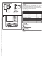
VIDEO ENTRY KIT
LIVISTAR-B-N
INSTALLATION MANUAL
FG00902M07 - ver. 1 - 07/2017
English - Manual code FG00902M07 - ver. 1 07/2017 - The data and information shown in this manual are to be considered subject to change at any time and without the need for any advance warning.

2
1
A
B
C
212
161
29
60
83,5
83,5
B
A
C
Page 2 - Manual code FG00902M07 - ver. 1 07/2017 - The data and information shown in this manual are to be considered subject to change at any time and without the need for any advance warning.
Page 3 - Manual code FG00902M07 - ver. 1 07/2017 - The data and information shown in this manual are to be considered subject to change at any time and without the need for any advance warning.
General Notes
• Read the instructions carefully before beginning the installa-
tion and carry out the actions as specified by the manufacturer.
• The installation, programming, commissioning and maintenance
of the product must only be carried out by qualified technicians,
properly trained in compliance with the regulations in force, inclu-
ding health and safety measures and the disposal of packaging.
• The installer must ensure that the information for the user,
where there is any, is provided and delivered.
• Before carrying out any cleaning or maintenance operation,
disconnect the devices from the power supply.
• The equipment must only be used for the purpose for which
it was expressly designed.
• The manufacturer declines all liability for any damage as a
result of improper, incorrect or unreasonable use.
This product complies with the relevant directives in force.
Decommissioning and disposal. Dispose of the packaging
and the device at the end of its life cycle responsibly, in com-
pliance with the laws in force in the country where the product
is used. The recyclable components are marked with a symbol
and the material's ID marker.
THE DATA AND INFORMATION SHOWN IN THIS MANUAL ARE TO
BE CONSIDERED AS SUBJECT TO CHANGE AT ANY TIME AND
WITHOUT THE NEED FOR ANY ADVANCE WARNING. MEASURE-
MENTS, UNLESS OTHERWISE INDICATED, ARE IN MILLIMETRES.
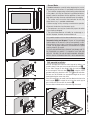
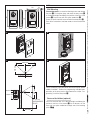
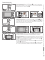
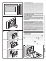
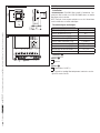
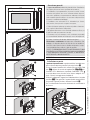
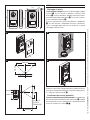
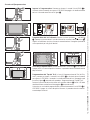
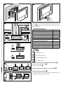
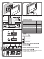
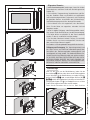
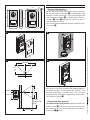
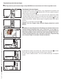
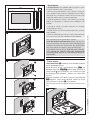
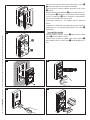
LIVIMN-B-N
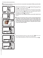
Wall-mounted installation
Unfasten the equipment from the metal support by letting it run
smoothly along it after you have pressed the plastic catch A.
Fix the metal support to the round Ø 60 mm back-box BA
or the rectangular 503 back-box BB BC using the screws
provided and paying attention to the (TOP) direction indication.
The box must be installed at an appropriate height for the user.
Avoid tightening the screws too much.
Once the connections are made, hook the video terminal onto the
metal support CD.To unhook the unit from the metal support
press the plastic catch and lift the terminal E.
For recessed installation refer to the recessing kit manual.

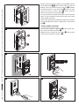
1
D E
F
G
LOCAL
BUS
LOCAL
BUS
A
B
CL.RES
M/S
LOCAL
SW1 SW3
SW4
M1
BUS
A
HCL.RES CL.RES CL.RES
XDV/304
1 2 3
IMASTER SLAVE
M/S M/S
Page 2 - Manual code FG00902M07 - ver. 1 07/2017 - The data and information shown in this manual are to be considered subject to change at any time and without the need for any advance warning.
Page 3 - Manual code FG00902M07 - ver. 1 07/2017 - The data and information shown in this manual are to be considered subject to change at any time and without the need for any advance warning.
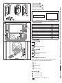
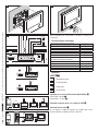
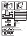
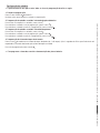
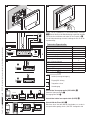
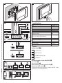
Technical Features
Type
LIVIMN-B-N
Power supply by BUS (VDC)
15÷20
Consumption (mA max)
410
Consumption in stand by (mA)
<1
Local power supply (VDC)
16÷18
Consumption (mA max)
370
Consumption of single LED (mA)
(panic, disabling ring)
1
Storage temperature (°C)
-25 ÷ +70
Operating temperature (°C)
0 ÷ +35
IP Rating
20
Video standard
PAL/NTSC
Display colour TFT LCD (pollici)
7
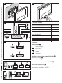
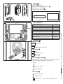
Features
Terminal board FA
+Local power supply
–
BBUS line input
+Doorbell
–
AL Alarm Input
Selection of source of power supply (BUS/LOCAL) G
Separate power supply A
Power supply by BUS B
Selection of last receiver on the line (CL.RES) H
Master/slave selection (M/S) I
In the event of a call, the caller’s picture is displayed only on
those receivers configured as “MASTER”s.

Page 4 - Manual code FG00902M07 - ver. 1 07/2017 - The data and information shown in this manual are to be considered subject to change at any time and without the need for any advance warning.
Page 5 - Manual code FG00902M07 - ver. 1 07/2017 - The data and information shown in this manual are to be considered subject to change at any time and without the need for any advance warning.
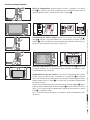
Setting melodies
☞ All the programming stages described below must be carried out in sequence:
1- Going into Programming.
Press button 5 times in 5 secs.
A short beep confirms that you have entered programming mode.
2- Programming the melody associated with a call from the entry panel.
To listen to the melodies in sequence, press key .
To select the melody and exit programming, press key .
To select the melody and continue with programming, press key .
3- Programming the melody associated with a call from the front door.
To listen to the melodies in sequence, press key .
To select the melody and exit programming, press key .
To select the melody and continue with programming, press key .
4- Programming the number of rings for the call.
Press key as many times as you want it to ring (from 1 to 6 rings). Three seconds after the last press of the key the call selected for
the chosen number of rings will be played back.
To exit programming, press key .
☞ See the entry panel documentation for call programming.

A
43,5
45
7,5 57
70
106
A
B
64,5
70
145
43,5
45
7,5 57
70
106
A
B
64,5
70
145
M2M1
+–
AB
Page 4 - Manual code FG00902M07 - ver. 1 07/2017 - The data and information shown in this manual are to be considered subject to change at any time and without the need for any advance warning.
Page 5 - Manual code FG00902M07 - ver. 1 07/2017 - The data and information shown in this manual are to be considered subject to change at any time and without the need for any advance warning.
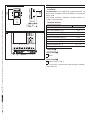
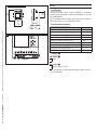
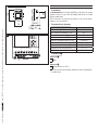
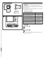
LIVI-AS
Installation
The power supplier must ALWAYS be installed horizontally. The
device can be installed on a DIN rail (EN 50022) in an appropriate
electric panel.
NOTE. Proper ventilation is required if the power supplier is in-
stalled in a metal container.
Technical features
Type
LIVI-AS
Power supply [V AC] 230
Max current demand [A AC]
0,2
Max energy dissipation [W] 10
Nominal power supply [V DC] 18
Nominal current demand [A DC]
1 for 1’
Nominal current demand [A DC] 0.5 for 3’
Storage temperature [°C] -25 ÷ +70
Operating temperature [°C]
0 ÷ +35
IP Rating [IP] 30
Features A
Terminal board A
~Mains
~
Terminal board B
–
+Power supply 18 VDC (*)
(*) The appliance is electronically protected against overloads
and short circuits.

A
C
500 mm
1080 mm
77¡
94¡
800 mm
500 mm
163,5 mm
43,5 mm
500 mm
1080 mm
77¡
94¡
800 mm
500 mm
163,5 mm
43,5 mm
B
D
135
99 30
3.5
6.5
243
207
135
99 30
3.5
6.5
243
207
Page 6 - Manual code FG00902M07 - ver. 1 07/2017 - The data and information shown in this manual are to be considered subject to change at any time and without the need for any advance warning.
Page 7 - Manual code FG00902M07 - ver. 1 07/2017 - The data and information shown in this manual are to be considered subject to change at any time and without the need for any advance warning.
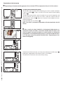
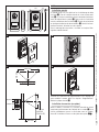
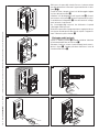
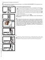
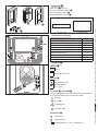
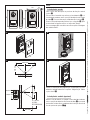
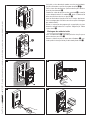
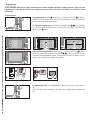
LIVIPR
Wall Mounting
With the Allen wrench unscrew the blocking screws and remove
the plate A. Fix the given plugs and screw the entry panel B
at the desired height considering the position of the lens of the
camera C. Run the hose with the system conductors B.
Extract the plastic terminal cover and wire the connections D.
Once all the connections have been made, re-insert the terminal
covers.
For the installation of the accessories refer to the chapter “Button
module installation”. Perform the programming and adjustment
operations of the entry panel as described to the chapter “Pro-
gramming”. Install the front plate A.
Recessed Installation (optional)
Install the recessed box at the desired height considering the
position of the lens of the camera C, but in advance, run the
hose with the system conductors through one of the breaking
points F A.
H= 165 cm
(RECOMMENDED
HEIGHT)

G
I
F
1
2
A
B
A
B
J
H
E
Page 6 - Manual code FG00902M07 - ver. 1 07/2017 - The data and information shown in this manual are to be considered subject to change at any time and without the need for any advance warning.
Page 7 - Manual code FG00902M07 - ver. 1 07/2017 - The data and information shown in this manual are to be considered subject to change at any time and without the need for any advance warning.
During installation of the recessed box use the provided spacer to
prevent deformation F B. With the Allen wrench unscrew the
blocking screws and remove the entry panel plate A. Introduce
the cable connections in the special hole B and fix the entry
panel on the frame as shown in figure G; extract the plastic
terminal cover and wire the connections D.
Once the connections have been made and re-insert the terminal
covers. For the installation of the accessories refer to the chapter
“Button module installation”.
Perform the programming and adjustment operations of the entry
panel as described to the chapter “Programming”. Install the front
plate A.
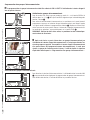
Button module installation
Insert the button module as highlighted H paying special atten-
tion to the top to bottom orientation J.
Remove the glass and write the user names I, paying special
attention to the orientation of the glass J.

K
1
4
3
B
M1
BOUT
M2
SW3
PROG RESET
LED PROG
M1
BOUT
M2
SW3
PROG RESET
PROG
4
A3
B
E
L
Page 8 - Manual code FG00902M07 - ver. 1 07/2017 - The data and information shown in this manual are to be considered subject to change at any time and without the need for any advance warning.
Page 9 - Manual code FG00902M07 - ver. 1 07/2017 - The data and information shown in this manual are to be considered subject to change at any time and without the need for any advance warning.
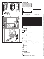
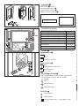
Accessories K
LIVIPR-PS single button A,
LIVIPR-TP Wall roof B,
Recessed box LIVIPR-SI 3,
Recessed frame LIVIPR-CI d.
Technical features
Type LIVIPR
Power supply [V AC] 16-18
Consumption [mA] 250
Consumption in stand by [mA] 100
Storage temperature [°C] -25 ÷ +70
Operating temperature [°C) -15 ÷ +50
IP Rating [IP] 54
Standard video PAL/NTSC
Resolution [pixel]
680x512
Minimum lighting [LUX] 1
Features L
Terminal board A
BOUT Riser
+Power supply 16-18 VDC
–
Terminal board B
–Earth
Door lock release button (NA)
Solenoid lock
12 V 1 A max
–
PROG key C and PROG LED d
Programming key and LED (see 'Programming' paragraph).
The PROG LED can take on the following states:
O
On
Slow flashing
Quick flashing
Adjustments E
loudspeaker audio
microphone audio
Solenoid lock 1-10 s. (default 1 s)
Personalized labels, dimensions
53x13x0,3 mm 53x33x0,3 mm

SW3
PROG RESET
PROG
SW3
PROG RESET
PROG
>3’’
<6’’
B
4
5
SW3
PROG RESET
PROG
M1
BOUT
PROG
M2
M1
BOUT
PROG
M2
33 A
6
beep
A
7SW3
PROG RESET
PROG
<1’’
Page 8 - Manual code FG00902M07 - ver. 1 07/2017 - The data and information shown in this manual are to be considered subject to change at any time and without the need for any advance warning.
Page 9 - Manual code FG00902M07 - ver. 1 07/2017 - The data and information shown in this manual are to be considered subject to change at any time and without the need for any advance warning.
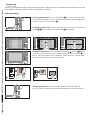
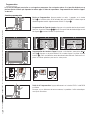
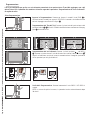
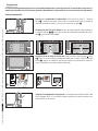
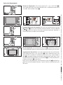
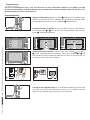
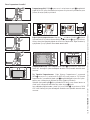
Programming
The kit is pre-configured to manage a single call originating from a single entry panel. One or more receivers answering the same call
can be added, by following the below “Call button programming” procedure.
Initial programming
Accessing programming. Press the PROG button A for at least 3 seconds and re-
lease it (within 6 seconds) as soon as the PROG LED comes on and the backlighting on
the buttons flashes as shown in figure B.
Programming button type. Press the first button on the entry panel in the position
marked 3/3A until the backlit LEDS stop flashing 4 and remain lit.
Programming the call keys. Press the door lock release and AUX2 5 buttons.
On the entry panel, press the call key to associate with the internal extension F: an
acoustic signal will confirm that the setting was stored. Hang up the receiver again.
Repeat the same operations for the other extensions.
Exiting programming. Briefly press the PROG button: the PROG LED goes o.
N.B. If no action is performed, the procedure will automatically end after 30 minutes.

5
2
SW3
PROG RESET
PROG
SW3
PROG RESET
PROG
<1’’
M1
BOUT
PROG
M2
SW3
PROG RESET
PROG
>3’’
<6’’
I
SW3
PROG RESET
PROG
>3’’
<6’’
A
6
34
beep
SW3
PROG RESET
PROG
G
M1
BOUT
PROG
M2
8
Page 10 - Manual code FG00902M07 - ver. 1 07/2017 - The data and information shown in this manual are to be considered subject to change at any time and without the need for any advance warning.
Page 11 - Manual code FG00902M07 - ver. 1 07/2017 - The data and information shown in this manual are to be considered subject to change at any time and without the need for any advance warning.
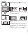
Reprogramming procedure
Accessing programming. Press the PROG button A for at least 3 seconds and re-
lease it (within 6 seconds) as soon as the PROG LED flashes and the backlighting on
the buttons comes on as shown in figure B.
Programming the call keys. Press the door lock release and AUX2 3 buttons.
On the entry panel, press the call key to associate with the internal extension 4: an
acoustic signal will confirm that the setting was stored. Hang up the receiver again.
Repeat the same operations for the other extensions.
Exiting programming. Briefly press the PROG button E: the PROG LED goes o. N.B.
If no action is performed, the procedure will automatically end after 30 minutes.
Programming button type. At the “Programming Call Buttons” stage, press the PROG
button F for at least 3 seconds and release it (within 6 seconds) as soon as the PROG
LED comes on and the backlighting on the buttons flashes as shown in figure G ,
entring the “Programming button type” procedure.
Press the first button on the entry panel in the position marked H until the backlit LEDS
stop flashing I and remain lit.
At the end, to exit programming, briefly press the PROG button E : the PROG LED goes
o. If no action is performed, the procedure will automatically end after 30 minutes.

SW3
PROG RESET
PROG
>8’’
<11’’
A
SW3
PROG RESET
PROG
M1
BOUT
SW3
PROG RESET
PROG
M2
2
3
4
3 beep
<1’’
M1
BOUT
SW3
PROG
RESET
PROG
M2
M1
BOUT
SW3
PROG
RESET
PROG
M2
1
2
Page 10 - Manual code FG00902M07 - ver. 1 07/2017 - The data and information shown in this manual are to be considered subject to change at any time and without the need for any advance warning.
Page 11 - Manual code FG00902M07 - ver. 1 07/2017 - The data and information shown in this manual are to be considered subject to change at any time and without the need for any advance warning.
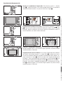
Programming an intercom group
y Programming an intercommunicating group must be carried out AFTER assigning the call key to all of the receivers.
Assigning intercommunicating groups
With the SW3 jumper inserted, press the PROG key for at least 8 seconds and release
it (within 11 seconds) 1 as soon as the PROG LED flashes and the key back lighting
comes on 2.
To enable the intercom function, go to the receiver that you want to programme, and
press the intercom call key you want to call from: a beep will sound to show that
programming has taken place 3. Repeat for all receivers to be included in the inter-
communicating group.
At the end, briefly press the PROG key 4.
NOTE: If no action is performed, the procedure will end automatically after 30
minutes.
y Once a receiver has been included in an intercommunicating group by as-
signing the intercom call button, it cannot be excluded from this group. If you
want to change the intercom call button on a receiver which has already been
programmed as an intercommunicating receiver, or you want to add new receiv-
ers to the group, repeat the operations detailed under “Programming an inter-
communicating group”.
Disabling the intercom function
To deactivate the intercom function, you simply have to disconnect the SW3 jumper 1;
by doing this, programming of the intercom system is also inhibited.
To reactivate this function you must restore factory settings.

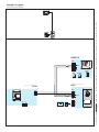
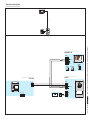
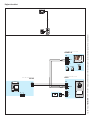
001CS2PLCO
+
BOUT
-
-
-
M1
+
–
M2
M2
A
001DC01LUXO
CL.RESM/S
001DC002AC
+
BOUT
-
+
-
M1
LOCAL
BUS
001DC002AC
2
2
2
2
2
2
2
2
001DC002AC
2
001DC002AC
2
2
2
001DC011AC
4
4
10
11
7
2
–
–
+
001DC011AC
CAME GATE
LIVIMN-B-N
LIVIPR
LIVI-AS
Page 12 - Manual code FG00902M07 - ver. 1 07/2017 - The data and information shown in this manual are to be considered subject to change at any time and without the need for any advance warning.
Page 13 - Manual code FG00902M07 - ver. 1 07/2017 - The data and information shown in this manual are to be considered subject to change at any time and without the need for any advance warning.
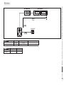
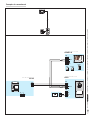
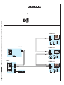
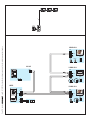
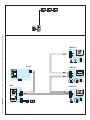
Connection examples

001CS2PLCO
+
BOUT
-
-
-
M2
+
–
M2
M1
001DC002AC
A
001DC01LUXO
CL.RESM/S
+
BOUT
-
+
-
M1
LOCAL
BUS
001DC01LUXO
CL.RESM/S
+
BOUT
-
+
-
M1
LOCAL
BUS
001DC01LUXO
CL.RESM/S
+
BOUT
-
+
-
M1
LOCAL
BUS
LIVIPR
LIVIMN-B-N
LIVIMN-B-N
LIVIMN-B-N
LIVI-AS
001DC002AC
2
2
2
2
2
2
2
2
001DC002AC
2
001DC002AC
2
2
2
001DC011AC
4
4
10
11
7
2
–
–
+
001DC011AC
CAME GATE
Page 12 - Manual code FG00902M07 - ver. 1 07/2017 - The data and information shown in this manual are to be considered subject to change at any time and without the need for any advance warning.
Page 13 - Manual code FG00902M07 - ver. 1 07/2017 - The data and information shown in this manual are to be considered subject to change at any time and without the need for any advance warning.

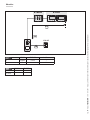
VCM/1D UTP CAT5
N° Master 1 1
N° Slave 4 1
VCM/1D UTP/CAT 5 2 x 2,5 mm2
La ≤100 m ≤30 m –
Lb ≤25 m – ≤60 m
La
La
N° Master N° Slave
Lb
LIVIPR
LIVI-AS
Page 14 - Manual code FG00902M07 - ver. 1 07/2017 - The data and information shown in this manual are to be considered subject to change at any time and without the need for any advance warning.
Page 15 - Manual code FG00902M07 - ver. 1 07/2017 - The data and information shown in this manual are to be considered subject to change at any time and without the need for any advance warning.
Distances

Page 14 - Manual code FG00902M07 - ver. 1 07/2017 - The data and information shown in this manual are to be considered subject to change at any time and without the need for any advance warning.
Page 15 - Manual code FG00902M07 - ver. 1 07/2017 - The data and information shown in this manual are to be considered subject to change at any time and without the need for any advance warning.

www.motostar-smarthome.com
contact@motostar-smarthome.com
è un marchio registrato di
Label Habitat SaS - 10 rue Léo Lagrange - 27950 Saint Marcel - France
English - Manual code FG00902M07 - ver. 1 07/2017 - The data and information shown in this manual are to be considered subject to change at any time and without the need for any advance warning.

LIVI-ASLIVIMN-B-N LIVIPR
ITALY
MADE IN
W
A
R
R
A
N
T
Y
•
G
A
R
A
N
T
I
E
•
G
A
R
A
N
Z
I
A
•
G
A
R
A
N
T
I
A
•
G
A
R
A
N
T
I
E
•
G
A
R
A
N
T
I
E
•
Y
E
A
R
S
•
A
N
S
•
A
N
N
I
•
A
Ñ
O
S
•
A
N
O
•
J
A
H
R
E
•
3
English
Français
Italiano
Español
Português
Deutsch
Türk
VIDEO KIT
LIVISTAR-B-N
MANUEL D'INSTALLATION
FG00902M07 - ver. 1 - 07/2017
Français - Code manuel FG00902M07 - vers. 1 07/2017 - Le contenu de ce manuel est susceptible de subir des modifications à tout moment et sans aucun préavis.

2
1
A
B
C
212
161
29
60
83,5
83,5
B
A
C
Page 2 - Code manuel FG00902M07 - vers. 1 07/2017 - Le contenu de ce manuel est susceptible de subir des modifications à tout moment et sans aucun préavis.
Instructions générales
• Lire attentivement les instructions, avant de commencer l'instal-
lation et eectuer les interventions comme indiqué par le fabricant.
• L'installation, la programmation, la mise en service et l'entre-
tien du produit ne doivent être eectués que par un personnel
technique qualifié et convenablement formé, conformément
aux normes en vigueur, y compris les dispositions concernant
la prévention des accidents et l'élimination des emballages.
• L’installateur doit veiller à ce que les informations pour l'usa-
ger, si prévues, soient présentes et remises.
• Avant d'eectuer toute opération de nettoyage ou d'entretien,
mettre les dispositifs hors tension.
• Les appareils doivent être utilisés uniquement aux fins pour
lesquels ils ont été conçus.
• Le fabricant ne saurait être tenu pour responsable des évent-
uels dommages dérivant d'une utilisation inadéquate, erronée
ou déraisonnable.
Le produit est conforme aux directives de référence en vigueur.
Démantèlement et élimination. Ne pas jeter les emballages et
l'appareil dans la nature à la fin du cycle de vie, mais veuillez les
éliminer conformément à la réglementation en vigueur dans le Pays
d'utilisation du produit. Les composants recyclables portent le sym-
bole et le sigle du matériau.
LES DONNÉES ET INFORMATIONS DE CE MANUEL SONT CONSI-
DÉRÉES COMME SUSCEPTIBLES DE MODIFICATIONS À TOUT MO-
MENT ET SANS PRÉAVIS. LES MESURES, SAUF AUTRES INDICA-
TIONS, SONT EXPRIMÉES EN MILLIMÈTRES.
LIVIMN-B-N
Installation murale
Décrocher l’appareil du support métallique, en le faisant glisser
sur lui-même après avoir appuyé sur la touche en plastique A.
Fixer le support métallique au boîtier à encastrer rond Ø 60 mm
BA ou au boîtier rectangulaire 503 BB BC à l’aide des
vis fournies et en respectant l’indication (TOP) . Le boîtier doit
être installé à une hauteur adéquate pour l’usager. Éviter de trop
serrer les vis. Après avoir eectué les branchements, fixer le ter-
minal vidéo au support métallique CD.
Pour décrocher l’appareil du support métallique, appuyer sur le
crochet en plastique et soulever le terminal E.

1
D E
F
G
LOCAL
BUS
LOCAL
BUS
A
B
CL.RES
M/S
LOCAL
SW1 SW3
SW4
M1
BUS
A
HCL.RES CL.RES CL.RES
XDV/304
1 2 3
IMASTER SLAVE
M/S M/S
Page 2 - Code manuel FG00902M07 - vers. 1 07/2017 - Le contenu de ce manuel est susceptible de subir des modifications à tout moment et sans aucun préavis.
Page 3 - Code manuel FG00902M07 - vers. 1 07/2017 - Le contenu de ce manuel est susceptible de subir des modifications à tout moment et sans aucun préavis.
Pour l’installation par encastrement, consulter la notice du kit
à encastrer.
Caractéristiques techniques
Type
LIVIMN-B-N
Alimentation : via BUS (VDC)
15÷20
Absorption (mA max)
410
Absorption en veille (mA)
<1
Alimentation locale (VDC)
16÷18
Absorption (mA max)
370
Absorption simple LED (mA)
(panique, désactivation sonnerie)
1
Température de stockage (°C)
-25 ÷ +70
Température de fonctionnement (°C)
0 ÷ +35
Indice IP
20
Standard vidéo
PAL/NTSC
Écran LCD TFT à couleurs (pouces)
7
Fonctions
Bornier FA
+Alimentation locale
–
BEntrée ligne BUS
+Appel palier
–
AL Entrée alarme
Sélection de la source d’alimentation (BUS/LOCAL) G
Alimentation séparée A
Alimentation : via BUS B
Sélection du dernier poste sur la ligne (CL.RES) H
Sélection Master/slave I
En cas d’appel, l’image de l’appelant ne s’ache que sur les
appareils dérivés configurés comme «MASTER».

Page 4 - Code manuel FG00902M07 - vers. 1 07/2017 - Le contenu de ce manuel est susceptible de subir des modifications à tout moment et sans aucun préavis.
Configuration des mélodies
☞ Eectuer, l’une après l’autre, toutes les phases de programmation décrites ci-après :
1- Entrée en mode programmation.
Appuyer 5 fois sur le bouton en 5 s.
Un signal sonore bref confirme l’entrée en mode programmation.
2- Programmation de la mélodie associée à l’appel provenant du poste externe.
Pour écouter les mélodies l’une après l’autre, appuyer sur la touche .
Pour sélectionner la mélodie et sortir de la programmation, appuyer sur la touche .
Pour sélectionner la mélodie et poursuivre la programmation, appuyer sur la touche .
3- Programmation de la mélodie associée à l’appel provenant du palier.
Pour écouter les mélodies l’une après l’autre, appuyer sur la touche .
Pour sélectionner la mélodie et sortir de la programmation, appuyer sur la touche .
Pour sélectionner la mélodie et poursuivre la programmation, appuyer sur la touche .
4- Programmation du nombre de sonneries de l’appel.
Appuyer sur la touche autant de fois que le nombre de sonneries souhaité (de 1 à 6 sonneries). Au bout de 3 secondes à compter
du dernier enfoncement de la touche, l’appel sélectionné sera reproduit selon le nombre de sonneries choisi.
Pour sortir du menu de programmation, appuyer sur la touche .
☞ Pour la programmation de l’appel, voir la documentation des postes externes.
Sayfa yükleniyor...
Sayfa yükleniyor...
Sayfa yükleniyor...
Sayfa yükleniyor...
Sayfa yükleniyor...
Sayfa yükleniyor...
Sayfa yükleniyor...
Sayfa yükleniyor...
Sayfa yükleniyor...
Sayfa yükleniyor...
Sayfa yükleniyor...
Sayfa yükleniyor...
Sayfa yükleniyor...
Sayfa yükleniyor...
Sayfa yükleniyor...
Sayfa yükleniyor...
Sayfa yükleniyor...
Sayfa yükleniyor...
Sayfa yükleniyor...
Sayfa yükleniyor...
Sayfa yükleniyor...
Sayfa yükleniyor...
Sayfa yükleniyor...
Sayfa yükleniyor...
Sayfa yükleniyor...
Sayfa yükleniyor...
Sayfa yükleniyor...
Sayfa yükleniyor...
Sayfa yükleniyor...
Sayfa yükleniyor...
Sayfa yükleniyor...
Sayfa yükleniyor...
Sayfa yükleniyor...
Sayfa yükleniyor...
Sayfa yükleniyor...
Sayfa yükleniyor...
Sayfa yükleniyor...
Sayfa yükleniyor...
Sayfa yükleniyor...
Sayfa yükleniyor...
Sayfa yükleniyor...
Sayfa yükleniyor...
Sayfa yükleniyor...
Sayfa yükleniyor...
Sayfa yükleniyor...
Sayfa yükleniyor...
Sayfa yükleniyor...
Sayfa yükleniyor...
Sayfa yükleniyor...
Sayfa yükleniyor...
Sayfa yükleniyor...
Sayfa yükleniyor...
Sayfa yükleniyor...
Sayfa yükleniyor...
Sayfa yükleniyor...
Sayfa yükleniyor...
Sayfa yükleniyor...
Sayfa yükleniyor...
Sayfa yükleniyor...
Sayfa yükleniyor...
Sayfa yükleniyor...
Sayfa yükleniyor...
Sayfa yükleniyor...
Sayfa yükleniyor...
Sayfa yükleniyor...
Sayfa yükleniyor...
Sayfa yükleniyor...
Sayfa yükleniyor...
Sayfa yükleniyor...
Sayfa yükleniyor...
Sayfa yükleniyor...
Sayfa yükleniyor...
Sayfa yükleniyor...
Sayfa yükleniyor...
Sayfa yükleniyor...
Sayfa yükleniyor...
Sayfa yükleniyor...
Sayfa yükleniyor...
Sayfa yükleniyor...
Sayfa yükleniyor...
Sayfa yükleniyor...
Sayfa yükleniyor...
Sayfa yükleniyor...
Sayfa yükleniyor...
Sayfa yükleniyor...
Sayfa yükleniyor...
Sayfa yükleniyor...
Sayfa yükleniyor...
Sayfa yükleniyor...
Sayfa yükleniyor...
Sayfa yükleniyor...
Sayfa yükleniyor...
-
 1
1
-
 2
2
-
 3
3
-
 4
4
-
 5
5
-
 6
6
-
 7
7
-
 8
8
-
 9
9
-
 10
10
-
 11
11
-
 12
12
-
 13
13
-
 14
14
-
 15
15
-
 16
16
-
 17
17
-
 18
18
-
 19
19
-
 20
20
-
 21
21
-
 22
22
-
 23
23
-
 24
24
-
 25
25
-
 26
26
-
 27
27
-
 28
28
-
 29
29
-
 30
30
-
 31
31
-
 32
32
-
 33
33
-
 34
34
-
 35
35
-
 36
36
-
 37
37
-
 38
38
-
 39
39
-
 40
40
-
 41
41
-
 42
42
-
 43
43
-
 44
44
-
 45
45
-
 46
46
-
 47
47
-
 48
48
-
 49
49
-
 50
50
-
 51
51
-
 52
52
-
 53
53
-
 54
54
-
 55
55
-
 56
56
-
 57
57
-
 58
58
-
 59
59
-
 60
60
-
 61
61
-
 62
62
-
 63
63
-
 64
64
-
 65
65
-
 66
66
-
 67
67
-
 68
68
-
 69
69
-
 70
70
-
 71
71
-
 72
72
-
 73
73
-
 74
74
-
 75
75
-
 76
76
-
 77
77
-
 78
78
-
 79
79
-
 80
80
-
 81
81
-
 82
82
-
 83
83
-
 84
84
-
 85
85
-
 86
86
-
 87
87
-
 88
88
-
 89
89
-
 90
90
-
 91
91
-
 92
92
-
 93
93
-
 94
94
-
 95
95
-
 96
96
-
 97
97
-
 98
98
-
 99
99
-
 100
100
-
 101
101
-
 102
102
-
 103
103
-
 104
104
-
 105
105
-
 106
106
-
 107
107
-
 108
108
-
 109
109
-
 110
110
-
 111
111
-
 112
112


diğer dillerde
- español: CAME Futura Guía de instalación
- italiano: CAME Futura Guida d'installazione
- português: CAME Futura Guia de instalação