
PM5D Editor Owner’s Manual
1
Special Notices
•The software and this owner’s manual are the exclu-
sive copyrights of Yamaha Corporation.
•Copying of the software or reproduction of this
manual in whole or in part by any means is expressly
forbidden without the written consent of the manu-
facturer.
•Copying of the commercially available music
sequence data and/or digital audio files is strictly
prohibited except for your personal use.
•Yamaha makes no representations or warranties
with regard to the use of the software and documen-
tation and cannot be held responsible for the results
of the use of this manual and the software.
•This disc is a CD-ROM. Do not attempt to play the
disc on an audio CD player. Doing so may result in
irreparable damage to your audio CD player.
•The screen displays as illustrated in this owner’s
manual are for instructional purposes, and may
appear somewhat different from the screens which
appear on your computer.
•Future upgrades of application and system software
and any changes in specifications and functions will
be announced separately.
•The company names and product names in this
Owner’s Manual are the trademarks or registered
trademarks of their respective companies.
❏
Yamaha Pro Audio Global Site
http://www.yamahaproaudio.com/
Contents
Getting Started ......................................... 2
INPUT CH window .................................... 6
ST IN window ............................................ 9
FX RTN window....................................... 11
MIX window ............................................ 13
MATRIX window...................................... 15
STEREO window ...................................... 17
DCA window............................................ 19
Selected Channel window....................... 20
Patch Editor window............................... 38
Surround Editor window......................... 42
GEQ window............................................ 44
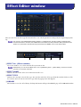
Effect Editor window............................... 46
DCA/Mute Group window...................... 50
Scene window ......................................... 53
Library window ....................................... 60
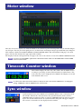
Meter window ......................................... 62
Timecode Counter window..................... 62
Sync window ........................................... 62
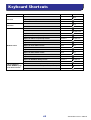
Keyboard Shortcuts................................. 63
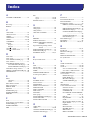
Index........................................................ 64
*Specifications and descriptions in this owner ’s manual are
for information purposes only. Yamaha Corp. reserves the
right to change or modify products or specifications at any
time without prior notice. Since specifications, equipment
or options may not be the same in every locale, please
check with your Yamaha dealer.
PM5D Editor
PM5D Editor
PM5D Editor
Owner’s Manual
Owner’s Manual
Owner’s Manual
Description of menus and buttons
In the event that menu and button names on a Windows system are different from those on a Macintosh, this
manual uses the Windows menu and button names followed by the Macintosh menu and button names in paren-
theses.

PM5D Editor Owner’s Manual
2
Overview of PM5D Editor
PM5D Editor enables you to remotely control the Yamaha PM5D mixing console and to save the parameter settings
on your computer. To use PM5D Editor, you must first perform the following operations:
1 Start and configure Studio Manager.
2 Start and configure PM5D Editor.
3 Synchronize PM5D Editor with your PM5D console (
➥
p.3).
For more information on using Studio Manager, refer to the Studio Manager Owner’s Manual.
Configuring PM5D Editor
You must configure the following settings for each open Editor.
• Specify MIDI ports in the Setup window of Studio Manager before making the following settings.
•To open each Editor, double-click the icon of the console or device you want to edit.
❏
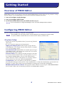
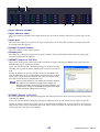
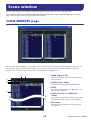
System Setup
To open the System Setup window, choose [System Setup] from the
[File] menu.
Be sure to specify the Input port and Output port.
Input port/Output port:
From the ports you specified in
Studio Manager, select the ports that the editor will use to commu-
nicate with the PM5D console.
Console Device ID:
PM5D Editor can control any one of up to
eight PM5D consoles, each with its own exclusive ID. Select the ID
of the console you want to control.
Channel Select:
These options determine whether or not chan-
nel selection is linked. When the PC->Console option is on, select-
ing a channel in PM5D Editor selects the same channel on the
console. When the Console->PC option is on, selecting a channel
on the console selects the same channel in PM5D Editor.
Confirmation:
These check boxes specify whether a confirma-
tion dialog box will appear when you store (Store Confirmation), recall (Recall Confirmation), patch (Patch Con-
firmation), or make a patch change that would modify an existing patch (Steal Patch Confirmation).
Window Control from Console:
This option determines whether or not using the USER DEFINED KEYS
on the console enables you to remotely open and close the PM5D Editor windows.
Getting Started
NOTE
NOTE

PM5D Editor Owner’s Manual
3
❏
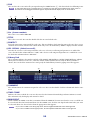
Console Setup
To open the Mixer Setup window, choose [Mixer Setup] from
the [File] menu.
Pair Mode:
Select whether faders will be paired Horizontally
or Vertically.
Pan Nominal Position:
Select whether the signal will be at
nominal level when panned to the center (Center) or when
panned all the way to left or right (L<->R). You can make sepa-
rate settings for monaural channels and paired channels.
Bus Setup:
Select the MIX bus mode (VARI/FIXED) for
every two adjacent odd-numbered/even-numbered MIX buses.
MIX buses assigned as surround buses are indicated as “SUR-
ROUND” and cannot be changed.
Surround Bus Allocation:
Select the MIX buses (MIX 1–
8 or MIX 9–16) that will be used as surround buses.
Stereo B:
Specify whether the same signal as the STEREO A
bus will be sent to the STEREO B bus (Stereo Bus), or whether
the STEREO B bus will function as the CENTER bus for LCR
mode (Center Bus).
Surround Mode:
Select the surround mode (STEREO, 3-1,
5.1, 6.1).
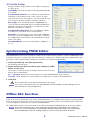
Synchronizing PM5D Editor
When PM5D Editor starts up, the parameter settings on the console and the parameter settings in PM5D Editor may
be different. Therefore, you must first match the parameter settings on the console with those in PM5D Editor. This
operation is called “synchronization.” Follow the steps below to synchronize PM5D Editor.
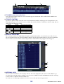
1 Select [Synchronize], then [Re-synchronize].
The following window opens.
2 Select whether you want to transfer your settings to PM5D
Editor, or vice versa.
At this time, the All Libs option determines whether or not Scene and
Library data is synchronized.
PC -> Console:
Tr ansfers the current parameter settings in PM5D Editor to your console.
Console -> PC:
Tr ansfers the current parameter settings of your console to the PM5D Editor.
3 Click [OK].
Do not operate the console while synchronization is in progress.
If you use the “Total Recall” function in Studio Manager, all selected Editors in Studio Manager are syn-
chronized with the corresponding devices.
Offline Edit Function
If you do not want to synchronize your console with PM5D Editor, select [Offline Edit] from the [Synchronization]
menu. To apply your off-line edits to your console, select [Re-Synchronize] from the [Synchronization] with the PC
-> Console option to synchronize the console with PM5D Editor.
The Offline Edit function is also activated when you click the [ONLINE]/[OFFLINE] button in the Sync window.
Some effect parameters in the console change their displayed values depending on the sampling fre-
quency. If you switch PM5D Editor from OFFLINE to ONLINE, displayed parameter values may change
because PM5D Editor loads the sampling frequency from the console and updates the display.
NOTE
NOTE

PM5D Editor Owner’s Manual
4
Working with Sessions
All of your console’s mix settings in PM5D Editor, including Scene and library data, are called Sessions. The follow-
ing table describes how to handle Sessions.
When you save a session in the window of an editor, the settings of only that editor will be saved in a file. Session files
saved by PM5D Editor have a filename extension of “.YSE”. Files in which only the PM5D console data is saved (file-
name extension “.PM5”) can also be handled, allowing you to use a memory card to exchange data with the PM5D
console.
If you save a Session in the Studio Manager window, all selected Editor settings are saved in a file with a file extension
of “.YSM.”
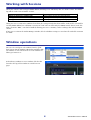
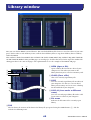
Window operations
You can select and open each window from the [Win-
dows] menu. For the INPUT CH window and Effect Edi-
tor window, use the sub-menu to select the channels or
library you want to see.
In the Library window or Scene window, click the tabs
located at the top of the window to switch between
pages.
Creating a new Session
Choose [New Session] from the [File] menu.
Opening a previously saved Session
Choose [Open Session] from the [File] menu.
Saving the current Session
Choose [Save Session] from the [File] menu.
Saving the current Session with a new name
Choose [Save Session As...] from the [File] menu.

PM5D Editor Owner’s Manual
5
Undo/Redo Function
In PM5D Editor, you can cancel the latest operation (Undo) and also cancel the cancellation of the latest operation
(Redo). If you perform an Undo operation twice in a row, you can cancel the two most-recent operations. If you per-
form an Undo operation three times in a row, you can cancel the three most-recent operations. In this way, you can
cancel multiple recent operations. The following table describes how to use the Undo/Redo function.
Please note, however, that after you perform one of the following operations, you cannot successfully undo or redo
any previous operation:
•Operations on the PM5D console
• Quitting Studio Manager
•Changing the surround mode or pair mode
•Synchronizing with the PM5D console
•Session operations
•The GEQ [EQ FLAT] button
•Moving the fader positions by changing the GEQ variable width
You cannot Undo or Redo the following operations:
• Edits in the Setup window
• Synchronization
• Opening and closing the windows
• Resizing the windows
In the Library window, you can Undo or Redo only the most recent operation. You cannot cancel the pre-
ceding operations.
Other Functions
❏
Resetting to the default value (Ctrl ( ) + click)
Move the cursor to a control or a parameter value, then hold down the <Ctrl> key ( ) and click the mouse but-
ton to reset the value to the default (e.g., to reset an Input Channel fader to –
∞
, or reset a pan setting to Center).
❏
Ctrl ( ) +Shift+Click
Move the cursor to a fader or AUX Send control, then hold down the <Ctrl> key ( ) and <Shift> key and click
the mouse button to reset the value to the nominal level.
Undo
Choose [Undo] from the [Edit] menu.
Redo
Choose [Redo] from the [Edit] menu.
NOTE
NOTE

PM5D Editor Owner’s Manual
6
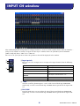
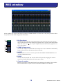
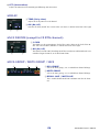
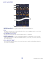
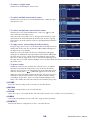
This window displays the mix parameters of input channels 1–24 or 25–48. The window shows either the channel 1–
24 layer or the channel 25–48 layer. To open the other layer’s window, choose the [Windows] menu command
[INPUT CH] and choose “CH1-24” or “CH25-48.”
You can use the [View] menu to choose the parameters that will be displayed in the window.
A
Input patch
Here you can select an input source to assign to the input channel, from the following
choices.
B
+48V
Switches on/off the phantom power (+48V) of the internal head amp (PM5D-RH
model only) or of the external head amp (AD8HR, AD824) patched to the input chan-
nel.
C
HA GAIN
Drag the knob in the screen to adjust the gain of the internal head amp (PM5D-RH
model only) or of the external head amp (AD8HR, AD824) patched to the input chan-
nel.
NONE
No assignment
AD1–AD48
INPUT jacks 1–48
AD1L–AD4R
L/R channels of ST IN jacks 1–4
SLOT1-1, SLOT1-2...SLOT4-15, SLOT4-16
Input channels of an I/O card installed in slots
1–4
FXOUT1L, FXOUT1R...FXOUT8R,
FXOUT8L
L/R outputs of internal effects 1–8
2TR D1L, 2TR D1R...2TR D3L, 2TR D3R
L/R channels of 2TR IN DIGITAL jacks 1–3
2TR A1L, 2TR A1R...2TR A3L, 2TR A3R
L/R channels of 2TR IN ANALOG jacks 1/2
INPUT CH window
1
2
3

PM5D Editor Owner’s Manual
7
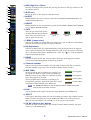
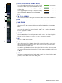
D
HPF (High Pass Filter)
Switches the high pass filter on/off. You can drag the numeric value up or down to edit
the cutoff frequency.
E
Ø (Phase)
Inverts the phase of the signal after AD conversion.
F
INSERT
Enables/disables the insert-out that is patched in the PM5D’s INSERT PATCH screen
(INPUT PATCH function).
G
DIRECT
Enables/disables the direct output that is patched in the PM5D’s DIRECT OUT PATCH
screen (INPUT PATCH function).
H
GATE
Tur ns the gate on/off. The indica-
tor immediately below the button
shows the gate’s on/off setting
and the open/closed status.
I
COMP (Compressor)
Switches the compressor on/off. When the compressor is on, the GR meter immediately
below the button shows the amount of gain reduction.
J
EQ (Equalizer)
Switches the EQ on/off. The graph immediately below the button shows the approxi-
mate response of the EQ. You can drag within the graph to edit the response of the EQ.
To reset the EQ to flat response, hold down the <Ctrl> key ( key) of your computer
keyboard and click the graph.
K
DELAY
Switches the delay on/off. You can also edit the delay time by dragging the numeric
value located immediately below the button up or down
L
Channel number
Indicates the input channel number corresponding to this module. You can double-
click this number to open the Selected Channel window for this channel.
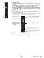
M
MIX SEND
The bar graphs in this area indicate the send levels of
the signals sent from the input channel to VARI-type
MIX buses. You can also adjust the send levels by drag-
ging a bar graph to left or right.
The bar graph display will change according to the
send position (pre/post) and on/off status of the signal
sent from the input channel to the MIX buses.
For FIXED-type MIX buses, the bar graph is fixed at nominal level (0 dB),
and only the on/off status is shown.
N PAN
Sets the panning of the signal sent from the input channel to the STEREO bus.
O SELECT
Selects input channel for which you want to perform operations. This is linked with the
INPUT channel strip [SEL] keys on the PM5D panel. However it will no longer be
linked if you turn Channel Select off (➥ p.2) in the System Setup window.
P CH ON (Channel on) button
Switches the input channel on/off. This is linked with the INPUT channel strip CH
[ON] keys on the PM5D panel.
L
O
P
N
M
5
6
7
8
9
J
4
K
Gate= closed
(red)
Gate= open
(green)
Gate= off
Pre/on (green)
Pre/off (green)
Post/off (yellow)
Post/on (yellow)
NOTE

PM5D Editor Owner’s Manual
8
Q Channel name
This is a text box that displays the channel name. You can also edit the channel name in
this text box.
Note that while the channel number (
L) will not change even if you switch the pair
mode, the channel name display will change according to the pair mode.
For example if the CH1-24 layer is displayed, switching from Horizontal Pair mode to
Ve rtical Pair mode will change the channel name display from channels 1, 2, 3 ... 24, 25
to channels 1, 3, 5...45, 47.
R Fader
Adjusts the input level of the input channel. This is linked with the INPUT channel
strip faders on the PM5D panel.
The current fader value is shown in the numeric box immediately below the fader. The
level meter at the right of the fader shows the level of the input signal.
The numbers and
alphabetical letters at
the right of the fader
indicate the DCA
group and mute
groups to which that
channel belongs, and
show the Recall Safe
and Mute Safe status of
the channel.
S CUE
This button cue-monitors the signal of the input channel. This is linked with the
INPUT channel strip [CUE] keys on the PM5D panel.
Q
S
R
The numbers of DCA groups to which this
channel belongs are shown in yellow.
The numbers of mute groups to which this
channel belongs are shown in red.
If this channel is set to Recall Safe, the R
character is shown in orange.
If this channel is set to Mute Safe, the M char-
acter is shown in red.

PM5D Editor Owner’s Manual
9
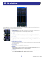
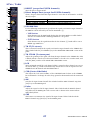
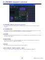
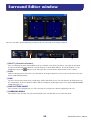
In this window you can view and edit the mix parameters of ST IN channels 1–4. You can use the [View] menu to
choose the parameters that will be displayed in the window.
A Input patch
Selects the input source that will be assigned to the ST IN channel. The input sources
that can be assigned are the same as for an input channel (➥ p.6).
B +48V
Switches on/off the phantom power (+48V) of the internal head amp (PM5D-RH
model only) or of the external head amp (AD824, AD8HR) patched to the ST IN chan-
nel.
C HA GAIN
Drag the knob in the screen to adjust the gain of the internal head amp (PM5D-RH
model only) or of the external head amp (AD824, AD8HR) patched to the ST IN chan-
nel.
D HPF (High Pass Filter)
Switches the high pass filter on/off. You can drag the numeric value up or down to edit
the cutoff frequency.
E Ø (Phase)
Inverts the phase of the signal after AD conversion.
F INSERT
Enables/disables the insert-out that is patched in the PM5D’s INSERT PATCH screen
(INPUT PATCH function). (The L/R settings are linked.)
G DIRECT
Enables/disables the direct out that is patched in the PM5D’s DIRECT OUT PATCH
screen (INPUT PATCH function). (The L/R settings are linked.)
ST IN window
5
6
7
1
2
3
4

PM5D Editor Owner’s Manual
10
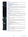
H GATE
Tur ns the gate on/off. The indicator immediately below the button shows the gate’s on/
off setting and the open/closed status (➥ p.7).
I COMP (Compressor)
Switches the compressor on/off. When the compressor is on, the GR meter immediately
below the button shows the amount of gain reduction.
J EQ (Equalizer)
Switches the EQ on/off (the L/R settings are linked). The graph immediately below the
button shows the approximate response of the EQ. You can drag the graph to edit the
response of the EQ, or hold down the <Ctrl> key ( key) of your computer keyboard
and click the graph to reset it to a flat response.
K DELAY
Switches the delay on/off. You can also edit the delay time by dragging the numeric
value located immediately below the button up or down
L Channel number
This is the number of the ST IN channel for this module. You can double-click this
number to open the Selected Channel window for this channel.
M MIX SEND
The send levels of the signals sent from the ST IN channel to the VARI-type MIX buses
are shown as bar graphs (the L/R settings are linked). You can also adjust the send levels
by dragging a bar graph to left or right.
The bar graph display will change according to the send position (pre/post) and on/off
status of the signal sent from the ST IN channel to the MIX buses (➥ p.7).
N PAN
Specifies the panning of the signal sent from the ST IN channel to the STEREO bus.
(You can set L and R separately.)
O SELECT
Selects the ST IN channel for which you want to perform operations. (L and R can be
selected separately.) This is linked with the ST IN channel strip [SEL] keys on the
PM5D panel. However it will no longer be linked if you turn Channel Select off (➥ p.2)
in the System Setup window.
P CH ON (Channel on) button
Switches the ST IN channel on/off (the L/R settings are linked). This is linked with the
ST IN channel strip CH [ON] keys on the PM5D panel.
Q Channel name
This is a text box that displays the channel name. You can also edit the channel name in
this text box.
R Fader
Adjusts the input level of the ST IN channel. This is linked with the faders of the ST IN
channel strip on the PM5D panel.
The numbers and alphabetical letters at the right of the fader indicate the DCA group
and mute groups to which that channel belongs, and show the Recall Safe and Mute
Safe status of the channel (➥ p.8).
S CUE
This button cue-monitors the signal of the ST IN channel (L/R are linked). This is
linked with the ST IN channel strip [CUE] keys on the PM5D panel.
O
Q
N
P
R
S
L
M
8
J
9
K

PM5D Editor Owner’s Manual
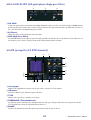
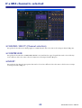
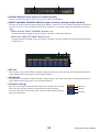
11
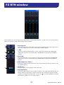
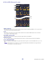
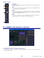
In this window you can view and edit the mix parameters of FX RTN channels 1–4. You can use the [View] menu to
choose the parameters that will be displayed in the window.
A Input patch
Selects the input source that will be assigned to the FX RTN channel. The input sources
that can be assigned are the same as for an input channel (➥ p.6).
B +48V
Switches on/off the phantom power (+48V) of the internal head amp (PM5D-RH
model only) or of the external head amp (AD8HR, AD824) patched to the FX RTN
channel.
C HA GAIN
Drag the knob in the screen to adjust the gain of the internal head amp (PM5D-RH
model only) or of the external head amp (AD8HR, AD824) patched to the FX RTN
channel.
D HPF (High Pass Filter)
Switches the high pass filter on/off. You can drag the numeric value up or down to edit
the cutoff frequency.
E Ø (Phase)
Inverts the phase of the signal after AD conversion.
F EQ (Equalizer)
Switches the EQ on/off (the L/R settings are linked). The graph immediately below the
button shows the approximate response of the EQ. You can drag the graph to edit the
response of the EQ, or hold down the <Ctrl> key ( key) of your computer keyboard
and click the graph to reset it to a flat response.
FX RTN window
6
1
2
5
3
4

PM5D Editor Owner’s Manual
12
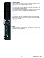
G Channel number
This is the number of the FX RTN channel for this module. You can double-click this
number to open the Selected Channel window for this channel.
H MIX SEND
The send levels of the signals sent from the FX RTN channel to the VARI-type MIX
buses are shown as bar graphs (the L/R settings are linked). You can also adjust the send
levels by dragging a bar graph to left or right.
The bar graph display will change according to the send position (pre/post) and on/off
status of the signal sent from the FX RTN channel to the MIX buses (➥ p.7).
I PAN
Specifies the panning of the signal sent from the FX RTN channel to the STEREO bus.
(You can set L and R separately.)
J SELECT
Selects the FX RTN channel for which you want to perform operations. (L and R can be
selected separately.) This is linked with the FX RTN channel strip [SEL] keys on the
PM5D panel. However it will no longer be linked if you turn Channel Select off (➥ p.2)
in the System Setup window.
K CH ON (Channel on) button
Switches the FX RTN channel on/off. (The L/R settings are linked.) This is linked with
the FX RTN channel strip CH [ON] keys on the PM5D panel.
L Channel name
This is a text box that displays the channel name. You can also edit the channel name in
this text box.
M Fader
Adjusts the input level of the FX RTN channel. This is linked with the faders of the FX
RTN channel strip on the PM5D panel.
The numbers and alphabetical letters at the right of the fader indicate the DCA group
and mute groups to which that channel belongs, and show the Recall Safe and Mute
Safe status of the channel (➥ p.8).
N CUE
This button cue-monitors the signal of the FX RTN channel (L/R are linked). This is
linked with the FX RTN channel strip [CUE] keys on the PM5D panel.
K
M
N
7
J
9
L
8

PM5D Editor Owner’s Manual
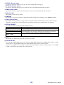
13
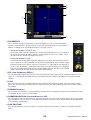
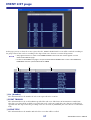
In this window you can view and edit the parameters of MIX channels 1–24. You can use the [View] menu to choose
the parameters that will be displayed in the window.
A EQ (Equalizer)
Switches the EQ on/off. The graph immediately below the button shows the approxi-
mate response of the EQ. You can drag the graph to edit the response of the EQ, or hold
down the <Ctrl> key ( key) of your computer keyboard and click the graph to reset
it to a flat response.
B COMP (Compressor)
Switches the compressor on/off. When the compressor is on, the GR meter immediately
below the button shows the amount of gain reduction.
C INSERT
Enables/disables the insert-out that is patched in the PM5D’s INSERT PATCH screen
(OUTPUT PATCH function).
D DELAY
Switches the delay on/off. You can also edit the delay time by dragging the numeric
value located immediately below the button up or down
E Channel number
Indicates the number of the MIX channel corresponding to this module. You can dou-
ble-click this number to open the Selected Channel window for this channel.
MIX window
5
4
1
3
2

PM5D Editor Owner’s Manual
14
F MTRX (Send level to MATRIX buses)
These bar graphs indicate the send levels of the signals
sent from the MIX channel to each MATRIX bus. You
can also adjust the send levels by dragging a bar graph
to left or right.
The bar graph display will change as follows according
to the send position (pre/post) and on/off status of the
signal sent from the MIX channel to the MATRIX
buses.
G TO ST (To STEREO)
This is an on/off switch for the signal sent from the MIX channel to the STEREO bus.
H PAN
Sets the panning of the signal sent from the MIX channel to the STEREO bus.
I VARI/FIXED
Indicates the type (VARI or FIXED) of the currently selected MIX bus. (This parameter
is for display only. You cannot switch between VARI and FIXED from within PM5D
Editor.)
If surround mode is enabled, MIX buses that are assigned as surround buses are dis-
played with the name of the surround channel (L, R, Ls, Rs ...), and the other MIX
buses are displayed as “FIXED.”
J SELECT
Selects the MIX channel for which you want to make settings. This is linked with the
MIX [SEL] keys in the MIX section of the PM5D panel. However it will no longer be
linked if you turn Channel Select off (➥ p.2) in the System Setup window.
K ON
Switches the MIX channel on/off.
L Fader
Adjusts the output level of the MIX channel. The current fader value is shown in the
numeric box immediately below the fader. The level meter at the right of the fader
shows the output level of the signal.
The numbers and alphabetical letters at the right of the fader indicate the DCA group
and mute groups to which that channel belongs, and show the Recall Safe and Mute
Safe status of the channel. (For the significance of the numbers and alphabetical letters,
see ➥ p.8).
M CUE
This button cue-monitors the signal of the MIX channel. This is linked with the MIX
[CUE] keys in the MIX section of the PM5D panel.
7
8
9
M
L
J
K
6
Pre/on (green)
Pre/off (green)
Post/off (yellow)
Post/on (yellow)

PM5D Editor Owner’s Manual
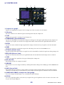
15
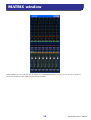
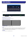
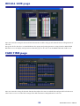
In this window you can view and edit the parameters of MATRIX channels 1–8. You can use the [View] menu to
choose the parameters that will be displayed in the window.
MATRIX window

PM5D Editor Owner’s Manual
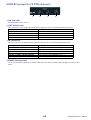
16
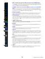
A MIX (Send levels from the MIX channels to the MATRIX bus)
Here you can view and edit the send levels of the signals sent from each MIX channel to
the MATRIX bus. The method of operation and the meaning of the display are the same
as for (
6) MTRX in the MIX window (➥ p.14).
B STEREO (Send levels from the STEREO channels to the MATRIX
bus)
Here you can view and edit the send levels of the signals sent from the STEREO A/B
channels to the MATRIX bus. The method of operation and the meaning of the display
are the same as for (
6) MTRX in the MIX window (➥ p.14).
C Channel number
Indicates the number of the MATRIX channel corresponding to this module. You can
double-click this number to open the Selected Channel window for this channel.
D EQ (Equalizer)
Switches the EQ on/off. The graph immediately below the button shows the approxi-
mate response of the EQ. You can drag the graph to edit the response of the EQ, or hold
down the <Ctrl> key ( key) of your computer keyboard and click the graph to reset
it to a flat response.
E COMP (Compressor)
Switches the compressor on/off. When the compressor is on, the GR meter immediately
below the button shows the amount of gain reduction.
F INSERT
Enables/disables the insert-out that is patched in the PM5D’s INSERT PATCH screen
(OUTPUT PATCH function).
G DELAY
Switches the delay on/off. You can also edit the delay time by dragging the numeric
value located immediately below the button up or down
H SELECT
Selects the MATRIX channel for which you want to make settings. This is linked with
the MATRIX [SEL] keys in the MATRIX section of the PM5D panel. However it will no
longer be linked if you turn Channel Select off (➥ p.2) in the System Setup window.
I ON
This switches the MATRIX channel on/off. This is linked with the MATRIX [ON] keys
in the MATRIX section of the PM5D panel.
J Fader
This adjusts the output level of the MATRIX channel. The current fader value is shown
in the numeric box immediately below the fader. The level meter at the right of the
fader shows the output level of the signal.
The numbers and alphabetical letters at the right of the fader indicate the DCA group
and mute groups to which that channel belongs, and show the Recall Safe and Mute
Safe status of the channel. (For the significance of the numbers and alphabetical letters,
see ➥ p.8).
K CUE
This button cue-monitors the signal of the MATRIX channel. This is linked with the
MATRIX [CUE] keys in the MATRIX section of the PM5D panel.
4
6
7
8
9
J
K
3
1
2
5

PM5D Editor Owner’s Manual
17
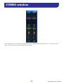
In this window you can view and edit the parameters of the STEREO A/B channels. You can use the [View] menu to
choose the parameters that will be displayed in the window.
STEREO window

PM5D Editor Owner’s Manual
18
A EQ (Equalizer)
Switches the EQ on/off (the L/R settings are linked). The graph immediately below the
button shows the approximate response of the EQ. You can drag the graph to edit the
response of the EQ, or hold down the <Ctrl> key ( key) of your computer keyboard
and click the graph to reset it to a flat response.
B COMP (Compressor)
Switches the compressor on/off (the L/R settings are linked). When the compressor is
on, the GR meter immediately below the button shows the amount of gain reduction.
C INSERT
Enables/disables the insert-out that is patched in the PM5D’s INSERT PATCH screen
(OUTPUT PATCH function). (The L/R settings are linked.)
D DELAY
Switches the delay on/off. (L/R settings can be made independently.) You can also edit
the delay time by dragging the numeric value located immediately below the button up
or down
E Channel number
This is the channel number (STEREO A or B) of this module. You can double-click this
number to open the Selected Channel window for this channel.
F MTRX (Send level to MATRIX buses)
Here you can view and edit the send levels of the signals sent from the STEREO A/B
channel to each MATRIX bus. The method of operation and the meaning of the display
are the same as for (
6) MTRX in the MIX window (➥ p.14).
G BALANCE
Adjusts the left/right balance of the STEREO A/B channel.
H SELECT
Selects the STEREO A/B channel for which you want to make settings. (You can specify
L and R independently.) This is linked with the STEREO [SEL] key in the STEREO A/B
channel strip of the PM5D panel. However it will no longer be linked if you turn Chan-
nel Select off (➥ p.2) in the System Setup window.
I ON
This switches the STEREO A/B channel on/off. This is linked with the STEREO [ON]
key in the STEREO A/B channel strip of the PM5D panel.
J Fader
Adjusts the output level of the STEREO A/B channel. This is linked with the STEREO
fader in the STEREO A/B channel strip of the PM5D panel.
The current fader value is shown in the numeric box immediately below the fader. The
level meter at the right of the fader shows the output level of the signal.
The numbers and alphabetical letters at the right of the fader indicate the DCA group
and mute groups to which that channel belongs, and show the Recall Safe and Mute
Safe status of the channel. (For the significance of the numbers and alphabetical letters,
see ➥ p.8).
K CUE
This button cue-monitors the signal of the STEREO A/B channel. This is linked with
the STEREO [CUE] key in the STEREO A/B channel strip of the PM5D panel.
J
K
9
7
8
1
3
4
5
6
2

PM5D Editor Owner’s Manual
19
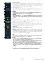
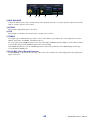
In this window you can view and edit the parameters of DCA groups 1–8.
A DCA number
This is the number of the DCA group.
B MUTE
This switches DCA group muting on/off. This is linked with the DCA [MUTE] keys in
the DCA strip section of the PM5D panel.
C DCA group name
This is a text box that displays the DCA group name. You can also edit the DCA group
name in this text box.
D DCA fader
This fader adjusts the level of the DCA group. This is linked with the DCA faders in the
DCA strip section of the PM5D panel.
The current fader value is shown in the numeric box immediately below the fader.
When you hold down the <Ctrl> key ( key) and <Shift> key of your computer key-
board and click a fader, the corresponding fader will be set to nominal level (0 dB).
When the fader is at nominal level, the N character at the right of the fader is displayed
in green.
If a DCA group is set to Recall Safe, the R character at the lower right of the fader is dis-
played in orange.
E CUE
This button cue-monitors the DCA group. This is linked with the DCA [CUE] keys in
the DCA channel strip of the PM5D panel.
DCA window
4
5
1
3
2

PM5D Editor Owner’s Manual
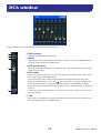
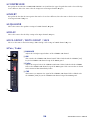
20
Here you can set the parameters of the currently selected input channel (input channels 1–48, ST IN channels 1–4,
FX RTN channels 1–4) or output channel (MIX channels 1–24, MATRIX channels 1–8, STEREO A/B channels).
The type of parameters that can be edited in this window will depend on the type of the currently selected channel.
The parameters of the Selected Channel window are explained below, in the order of input channels (input channels
1–48, ST IN channels 1–4, FX RTN channels 1–4), MIX channels, MATRIX channels, and STEREO A/B channels.
If an input channel is selected
Unless otherwise specified, the parameters explained below are common to input channels 1–48, ST IN
channels 1–4, and FX RTN channels 1–4.
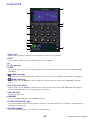
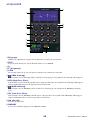
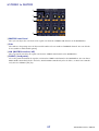
❏ CHANNEL SELECT (Channel selection)
A SELECT (Channel selection)
Indicates the number and name of the channel you are editing. To switch channels, use the SELECT button or the
/ buttons at left and right. You can also edit the channel name in the text box.
B PAIR
Indicates the pair status of the selected channel. You can click the heart symbol to enable/disable pairing.
C INPUT PATCH
Selects the input source assigned to the input channel (for the selectable input sources, ➥ p.6).
D LIBRARY
Accesses the INPUT CH page of the LIBRARY window.
Selected Channel window
NOTE
1 2 43
Sayfa yükleniyor ...
Sayfa yükleniyor ...
Sayfa yükleniyor ...
Sayfa yükleniyor ...
Sayfa yükleniyor ...
Sayfa yükleniyor ...
Sayfa yükleniyor ...
Sayfa yükleniyor ...
Sayfa yükleniyor ...
Sayfa yükleniyor ...
Sayfa yükleniyor ...
Sayfa yükleniyor ...
Sayfa yükleniyor ...
Sayfa yükleniyor ...
Sayfa yükleniyor ...
Sayfa yükleniyor ...
Sayfa yükleniyor ...
Sayfa yükleniyor ...
Sayfa yükleniyor ...
Sayfa yükleniyor ...
Sayfa yükleniyor ...
Sayfa yükleniyor ...
Sayfa yükleniyor ...
Sayfa yükleniyor ...
Sayfa yükleniyor ...
Sayfa yükleniyor ...
Sayfa yükleniyor ...
Sayfa yükleniyor ...
Sayfa yükleniyor ...
Sayfa yükleniyor ...
Sayfa yükleniyor ...
Sayfa yükleniyor ...
Sayfa yükleniyor ...
Sayfa yükleniyor ...
Sayfa yükleniyor ...
Sayfa yükleniyor ...
Sayfa yükleniyor ...
Sayfa yükleniyor ...
Sayfa yükleniyor ...
Sayfa yükleniyor ...
Sayfa yükleniyor ...
Sayfa yükleniyor ...
Sayfa yükleniyor ...
Sayfa yükleniyor ...
Sayfa yükleniyor ...
-
 1
1
-
 2
2
-
 3
3
-
 4
4
-
 5
5
-
 6
6
-
 7
7
-
 8
8
-
 9
9
-
 10
10
-
 11
11
-
 12
12
-
 13
13
-
 14
14
-
 15
15
-
 16
16
-
 17
17
-
 18
18
-
 19
19
-
 20
20
-
 21
21
-
 22
22
-
 23
23
-
 24
24
-
 25
25
-
 26
26
-
 27
27
-
 28
28
-
 29
29
-
 30
30
-
 31
31
-
 32
32
-
 33
33
-
 34
34
-
 35
35
-
 36
36
-
 37
37
-
 38
38
-
 39
39
-
 40
40
-
 41
41
-
 42
42
-
 43
43
-
 44
44
-
 45
45
-
 46
46
-
 47
47
-
 48
48
-
 49
49
-
 50
50
-
 51
51
-
 52
52
-
 53
53
-
 54
54
-
 55
55
-
 56
56
-
 57
57
-
 58
58
-
 59
59
-
 60
60
-
 61
61
-
 62
62
-
 63
63
-
 64
64
-
 65
65


Diğer dillerde
- español: Yamaha PM5D El manual del propietario
- français: Yamaha PM5D Le manuel du propriétaire
- italiano: Yamaha PM5D Manuale del proprietario
- svenska: Yamaha PM5D Bruksanvisning
- čeština: Yamaha PM5D Návod k obsluze
- polski: Yamaha PM5D Instrukcja obsługi
- Deutsch: Yamaha PM5D Bedienungsanleitung
- português: Yamaha PM5D Manual do proprietário
- English: Yamaha PM5D Owner's manual
- dansk: Yamaha PM5D Brugervejledning
- русский: Yamaha PM5D Инструкция по применению
- suomi: Yamaha PM5D Omistajan opas
- Nederlands: Yamaha PM5D de handleiding
- română: Yamaha PM5D Manualul proprietarului