Makita HR3011FC Kullanım kılavuzu
- Kategori
- Elektrikli matkaplar
- Tip
- Kullanım kılavuzu

HR3011FC
HR3012FC
HR3001C
EN Combination Hammer INSTRUCTION MANUAL 9
FR Marteau Combi MANUEL D’INSTRUCTIONS 18
DE Kombi-Hammer BETRIEBSANLEITUNG 28
IT Tassellatore combinato ISTRUZIONI PER L’USO 38
NL Combinatiehamer GEBRUIKSAANWIJZING 48
ES Martillo Rotativo Combinado MANUAL DE
INSTRUCCIONES 58
PT Martelete Combinado MANUAL DE INSTRUÇÕES 68
DA Kombinationshammer BRUGSANVISNING 78
EL 87
TR KULLANMA KILAVUZU 97

2
1
Fig.1
1
Fig.2
AB
1
Fig.3
1
32
Fig.4
2
4
1
3
Fig.5
1
2
Fig.6
1
Fig.7
1
Fig.8

3
1
Fig.9
1
Fig.10
1
Fig.11
1
2
Fig.12
1
Fig.13
1
2
Fig.14
1
Fig.15
1 2
4
3
Fig.16

4
1
Fig.17
2
3
1
Fig.18
2
111
Fig.19
1
2
Fig.20
Fig.21
2
111
Fig.22
1
2
Fig.23
Fig.24

5
1
Fig.25
Fig.26
2
1
4
3
Fig.27
1
Fig.28
1
Fig.29
1
Fig.30

6
2
1
Fig.31
1
A
Fig.32
1
2
Fig.33
1
Fig.34
1
Fig.35
Fig.36
1
Fig.37

7
1
2
Fig.38
2
1
Fig.39
Fig.40
Fig.41
2
1
Fig.42
1
2
Fig.43
Fig.44
Fig.45

8
1
2
Fig.46

9ENGLISH
ENGLISH (Original instructions)
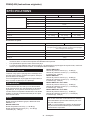
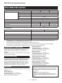
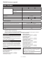
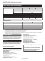
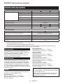
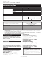
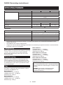
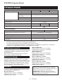
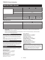
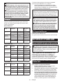
SPECIFICATIONS
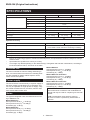
Model: HR3011FC HR3012FC HR3001C
Capacities Concrete 30 mm
Core bit 80 mm
Diamond core bit (dry type) 80 mm
Steel 13 mm
Wood 32 mm
No load speed 0 - 840 min-1
Blows per minute 0 - 4,500 min-1
Overall length 369 mm 386 mm 369 mm
Net weight 4.4 - 4.8 kg 4.5 - 4.7 kg 4.1 - 4.5 kg
Safety class /II
Model: DX10 (For HR3011FC) DX11 (For HR3012FC)
Applicable workpiece and workmode for concrete drilling only
(not for metal or wood, and not for core drilling or chiseling)
Suction performance 350 l/min
Operating stroke Up to 190 mm
Suitable drill bit Up to 265 mm
Net weight 1.2 kg
without notice.
EPTA-Procedure 01/2014, are shown in the table.
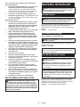
Intended use
The tool is intended for hammer drilling and drilling in
brick, concrete and stone as well as for chiselling work.
It is also suitable for drilling without impact in wood,
metal, ceramic and plastic.
The tool should be connected only to a power supply of
the same voltage as indicated on the nameplate, and
can only be operated on single-phase AC supply. They
are double-insulated and can, therefore, also be used
from sockets without earth wire.
Noise
The typical A-weighted noise level determined accord-
ing to EN62841-2-6:
Model HR3011FC
Sound pressure level (LpA) : 90 dB (A)
Sound power level (LWA) : 101 dB (A)
Uncertainty (K) : 3 dB (A)
Model HR3012FC
Sound pressure level (LpA) : 91 dB(A)
Sound power level (LWA) : 102 dB (A)
Uncertainty (K) : 3 dB(A)
Model HR3001C
Sound pressure level (LpA) : 92 dB(A)
Sound power level (LWA) : 103 dB (A)
Uncertainty (K) : 3 dB(A)
Model HR3011FC with DX10
Sound pressure level (LpA) : 93 dB(A)
Sound power level (LWA) : 104 dB (A)
Uncertainty (K) : 3 dB(A)
Model HR3012FC with DX11
Sound pressure level (LpA) : 93 dB(A)
Sound power level (LWA) : 104 dB (A)
Uncertainty (K) : 3 dB(A)
NOTE: The declared noise emission value(s) has
been measured in accordance with a standard test
method and may be used for comparing one tool with
another.
NOTE: The declared noise emission value(s)
may also be used in a preliminary assessment of
exposure.

10 ENGLISH
WARNING:
WARNING: The noise emission during actual
WARNING: -
trigger time).
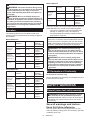
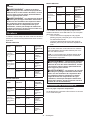
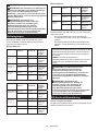
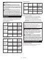
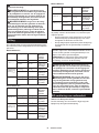
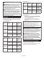
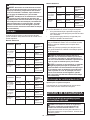
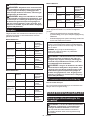
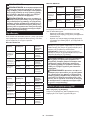
Vibration
The following table shows the vibration total value
(tri-axial vector sum) determined according to applica-
ble standard.
Model HR3011FC
Vibration
emission
standard /
Test condition
Hammer
drilling into
concrete
(ah, HD)
10.8 m/s21.5 m/s2EN62841-2-6
9.0 m/s21.6 m/s2
Recommended
practical
operation*
Hammer
drilling into
concrete with
DX10 (ah, HD)
10.4 m/s21.5 m/s2EN62841-2-6
8.1 m/s21.5 m/s2
Recommended
practical
operation*
Chiselling
(ah, CHeq)
9.7 m/s21.5 m/s2EN62841-2-6
9.9 m/s21.5 m/s2
Recommended
practical
operation*
Model HR3012FC
Vibration
emission
standard /
Test condition
Hammer
drilling into
concrete
(ah, HD)
10.5 m/s21.5 m/s2EN62841-2-6
8.7 m/s21.5 m/s2
Recommended
practical
operation*
Hammer
drilling into
concrete with
DX11 (ah, HD)
10.0 m/s21.5 m/s2EN62841-2-6
8.1 m/s21.5 m/s2
Recommended
practical
operation*
Chiselling
(ah, CHeq)
8.2 m/s21.5 m/s2EN62841-2-6
7.5 m/s21.6 m/s2
Recommended
practical
operation*
Model HR3001C
Vibration
emission
standard /
Test condition
Hammer
drilling into
concrete
(ah, HD)
12.2 m/s21.5 m/s2EN62841-2-6
17.3 m/s21.5 m/s2
Recommended
practical
operation*
Chiselling
(ah, CHeq)
10.4 m/s21.5 m/s2EN62841-2-6
12.4 m/s21.5 m/s2
Recommended
practical
operation*
* The test condition of recommended practical operation
meets EN 62841-2-6, except for the following points:
• Feed force is applied to the switch handle (main
• The side grip/handle (auxiliary handle) is held to
keep balance of the tool.
NOTE: The declared vibration total value(s) has been
measured in accordance with a standard test method
and may be used for comparing one tool with another.
NOTE: The declared vibration total value(s) may also
be used in a preliminary assessment of exposure.
WARNING: The vibration emission during
WARNING: -
trigger time).
For European countries only
The EC declaration of conformity is included as Annex A
to this instruction manual.
SAFETY WARNINGS
WARNING: -
Failure to follow all instructions
Save all warnings and instruc-
tions for future reference.
The term "power tool" in the warnings refers to your
mains-operated (corded) power tool or battery-operated
(cordless) power tool.

11 ENGLISH
ROTARY HAMMER SAFETY
WARNINGS
1. Exposure to noise can
cause hearing loss.
2.
tool.
3.
-
ing or its own cord. Cutting accessory contacting
a "live" wire may make exposed metal parts of the
power tool "live" and could give the operator an
electric shock.
1.
At higher
speeds, the bit is likely to bend if allowed to rotate
freely without contacting the workpiece, resulting
2.
Bits can
bend, causing breakage or loss of control, result-
1.
-
2.
3.
4. In cold weather or when the tool has not been
5.
sure no one is below when using the tool in
high locations.
6.
7.
8.
9.
10.
11.
-
12.
SAVE THESE INSTRUCTIONS.
WARNING:
FUNCTIONAL
DESCRIPTION
CAUTION:
Switch action
CAUTION:
released.
To start the tool, simply pull the switch trigger. Tool
speed is increased by increasing pressure on the switch
trigger. Release the switch trigger to stop.
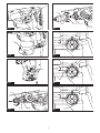
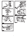
Fig.1: 1. Switch trigger
For HR3011FC, HR3012FC only
CAUTION:
To turn on the lamp, pull the switch trigger. Release the
Fig.2: 1. Lamp
NOTE:
the lamp. Be careful not to scratch the lens of lamp, or
it may lower the illumination.
Reversing switch action
CAUTION:
CAUTION:
Changing the
direction of rotation before the tool stops may dam-
age the tool.
NOTICE: When changing the direction of rota-
side or B side. Otherwise, when the switch trigger is
pulled, the motor may not rotate or the tool may not
work properly.
This tool has a reversing switch to change the direc-
tion of rotation. Move the reversing switch lever to the
position A side for clockwise rotation or to the position B
side for counterclockwise rotation.
Fig.3: 1. Reversing switch lever

12 ENGLISH
For HR3012FC only
The quick change chuck for SDS-plus can be easily
exchanged for the quick change drill chuck.
CAUTION: Before removing the quick change
chuck for SDS-plus, be sure to remove the bit.
Grasp the change cover of the quick change chuck for
SDS-plus and turn in the direction of the arrow until
the change cover line moves from the symbol to
the symbol. Pull forcefully in the direction of the arrow.
Fig.4: 1. Quick change chuck for SDS-plus
2. Change cover 3. Change cover line
Check the line of the quick change drill chuck shows
the symbol. Grasp the change cover of the quick
change drill chuck and set the line to the symbol.
Place the quick change drill chuck on the spindle of the
tool. Grasp the change cover of the quick change drill
chuck and turn the change cover line to the symbol
until a click can clearly be heard.
Fig.5: 1. Quick change drill chuck 2. Spindle
3. Change cover line 4. Change cover
Selecting the action mode
NOTICE: Do not rotate the action mode chang-
The tool will be
damaged.
NOTICE:
Rotation with hammering
For drilling in concrete, masonry, etc., rotate the action
mode changing knob to the symbol. Use a tungsten-
carbide tipped bit (optional accessory).
Fig.6: 1. Rotation with hammering 2. Action mode
changing knob
For drilling in wood, metal or plastic materials, rotate
the action mode changing knob to the symbol. Use a
twist drill bit or wood drill bit.
Fig.7: 1. Rotation only
For chipping, scaling or demolition operations, rotate
the action mode changing knob to the symbol. Use a
bull point, cold chisel, scaling chisel, etc.
Fig.8: 1. Hammering only
Torque limiter
NOTICE:
This will help pre-
vent premature wear of the tool.
NOTICE:
-
This is because they will cause
the torque limiter to actuate too frequently.
The torque limiter will actuate when a certain torque
level is reached. The motor will disengage from the
output shaft. When this happens, the drill bit will stop
turning.
Electronic function
The tool is equipped with the electronic functions for
easy operation.
• Constant speed control
The speed control function provides the constant
rotation speed regardless of load conditions.
Air duct
For HR3011FC, HR3012FC only
CAUTION:
duct.
get damaged.
The air duct is to connect to the dust collection system.
When using the dust collection system, read the section
about the dust collection system.
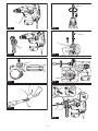
Fig.9: 1. Air duct
ASSEMBLY
CAUTION:
CAUTION:
CAUTION: After installing or adjusting the
secured.
To install the side grip, follow the steps below.
1. Loosen the thumb screw on the side grip.
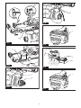
Fig.10: 1. Thumb screw
2. Attach the side grip while pressing the thumb
-
sions on the tool barrel.
Fig.11: 1. Thumb screw
3. Tighten the thumb screw to secure the grip. The

13 ENGLISH
Grease
Coat the shank end of the drill bit beforehand with a
small amount of grease (about 0.5 - 1 g).
This chuck lubrication assures smooth action and lon-
ger service life.
Installing or removing drill bit
Clean the shank end of the drill bit and apply grease
before installing the drill bit.
Fig.12: 1. Shank end 2. Grease
Insert the drill bit into the tool. Turn the drill bit and push
it in until it engages.
After installing the drill bit, always make sure that the
drill bit is securely held in place by trying to pull it out.
Fig.13: 1. Drill bit
To remove the drill bit, pull the chuck cover down all the
way and pull the drill bit out.
Fig.14: 1. Drill bit 2. Chuck cover
scaling or demolishing)
The chisel can be secured at the desired angle. To
change the chisel angle, rotate the action mode chang-
ing knob to the O symbol. Turn the chisel to the desired
angle.
Fig.15: 1. Action mode changing knob
Rotate the action mode changing knob to the sym-
bol. Then make sure that the chisel is securely held in
place by turning it slightly.
The depth gauge is convenient for drilling holes of
uniform depth.
Press and hold the lock button, and then insert the
depth gauge into the hex hole. Make sure that the
toothed side of the depth gauge faces the marking.
Fig.16: 1. Depth gauge 2. Lock button 3. Marking
4. Toothed side
release the lock button to lock the depth gauge.
NOTE: Make sure that the depth gauge does not
touch the main body of the tool when attaching it.
Optional accessory
Use the dust cup to prevent dust from falling over the
tool and on yourself when performing overhead drilling
operations. Attach the dust cup to the bit as shown in
attached to is as follows.
Model Bit diameter
Dust cup 5 6 mm - 14.5 mm
Dust cup 9 12 mm - 16 mm
Fig.17: 1. Dust cup
Optional accessory
NOTICE: When using the dust cup set in
HR3011FC, HR3001C, the spacer is also requied.
Before installing the dust cup set, remove the bit from
the tool if installed.
Attach the spacer to the dust cup set. symbol on the
dust cup is aligned with the groove in the spacer.
Fig.18: 1. Spacer 2. symbol 3. Groove
Install the dust cup set with the spacer on the tool so
that the symbol on the dust cup is aligned with the
groove in the tool.
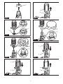
Fig.19: 1. symbol 2. Groove
To remove the dust cup set, remove the bit while pulling
the chuck cover in the direction of the arrow.
Fig.20: 1. Bit 2. Chuck cover
Hold the spacer and pull it out.
Fig.21
For Model HR3012FC
Before installing the dust cup set, remove the bit from
the tool if installed.
Install the dust cup set on the tool so that the sym-
bol on the dust cup is aligned with the groove in the tool.
Fig.22: 1. symbol 2. Groove
To remove the dust cup set, remove the bit while pulling
the chuck cover in the direction of the arrow.
Fig.23: 1. Bit 2. Chuck cover
Hold the root of dust cup and pull it out.
Fig.24
NOTE: If you connect a vacuum cleaner to the dust
cup set, remove the dust cap before connecting it.
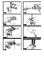
Fig.25: 1. Dust cap
NOTE:
it with its printed side facing up so that groove on the
Fig.26

14 ENGLISH
Tool hanger
Optional accessory
WARNING: Do not use damaged tool hanger
and screw.
WARNING:
WARNING:
CAUTION: Install or remove the tool hanger
on a stable table or surface.
The tool hanger is intended for connecting the lanyard
(tether strap). To install the tool hanger to the tool,
follow the steps below.
1. Disconnect the plug from the power source.
2.
holes on the tool.
3.
Fig.27: 1. Tool hanger 2. Hole 3.
4. Screw
DUST COLLECTION
SYSTEM
For HR3011FC, HR3012FC only
Optional accessory
The dust collection system is designed to collect dusts
Fig.28: 1. Dust collection system
CAUTION:
on the tool. Failure to do so may result in personal
CAUTION:
Failure to do so cause dust
inhalation.
CAUTION: -
aged. Failure to do so may cause dust inhalation.
NOTICE:
for core drilling or chiseling. The dust collection
system is intended for drilling only.
NOTICE:
for metal or wood. The dust collection system is
intended for concrete only.
NOTICE:
in wet environment. Failure to do so may cause
malfunction.
NOTE: The dust collection system collects the gener-
ated dust at a considerable rate, but not all dust can
be collected.
Installing or removing the dust
NOTICE: Before installing the dust collection
install the dust collection system. Particularly the foreign
matters on the electrical interface may cause malfunction.
If any dust remains on the air duct, the dust comes into the
Hook the dust collection system on the tool, and then
insert the dust collection system all the way, until it locks
in place with a little double click.
After that, make sure that the dust collection system is
securely installed.
Fig.29: 1. Air duct
When removing the dust collection system, press the
Fig.30: 1.
CAUTION:
the guide adjustment button.
the desired position.
Fig.31: 1. Guide 2.
while pushing it. The distance (A) is the drilling depth.
Fig.32: 1.
CAUTION:
Do not turn the dial on the dust case
while the dust case is removed from the dust collec-
Doing so may cause dust inhalation.
CAUTION:
turning the dial on the dust case. Turning the dial
while the tool is running may result in the loss of
control of the tool.
the number of times to dispose of the dust.
Turn the dial on the dust case three times after col-
lecting every 50,000 mm3 of dust or when you feel the
vacuum performance declined.
NOTE: 50,000 mm3 of dust equivalents to drilling 10
Fig.33: 1. Dust case 2. Dial

15 ENGLISH
CAUTION:
of dust.
CAUTION:
before the dust case becomes full. Failure to do so
may decrease the dust collection performance, and
then cause dust inhalation.
CAUTION:
as a guide.
performance, and then cause dust inhalation.
NOTICE:
1. Remove the dust case while pressing down the
lever of the dust case.
Fig.34: 1. Lever
2. Open the cover of the dust case.
Fig.35: 1. Cover
3.
Fig.36
1. Remove the dust case while pressing down the
lever of the dust case. (Refer to the section for dispos-
ing of dust.)
2.
Fig.37: 1. Filter cover
3.
Fig.38: 1. Filter 2. Filter case
4.
5. Close the cover of the dust case, and then attach
the dust case to the dust collection system.
If the sealing cap is worn out, the performance of the
dust collection decreases. Replace it if it is worn out.
Remove the sealing cap, and then attach a new one
with its protrusion facing upward.
Fig.39: 1. Protrusion 2. Sealing cap
OPERATION
CAUTION:
CAUTION: -
CAUTION:
CAUTION:
Fig.40
CAUTION: There is tremendous and sudden
twisting force exerted on the tool/drill bit at the time of
hole break-through, when the hole becomes clogged
with chips and particles, or when striking reinforcing
rods embedded in the concrete.
-
tions. Failure to do so may result in the loss of control
Set the action mode changing knob to the symbol.
Position the drill bit at the desired location for the hole,
then pull the switch trigger. Do not force the tool. Light
pressure gives best results. Keep the tool in position
and prevent it from slipping away from the hole.
Do not apply more pressure when the hole becomes
clogged with chips or particles. Instead, run the tool at
an idle, then remove the drill bit partially from the hole.
By repeating this several times, the hole will be cleaned
out and normal drilling may be resumed.
NOTE: Eccentricity in the drill bit rotation may occur
while operating the tool with no load. The tool auto-
matically centers itself during operation. This does not
Set the action mode changing knob to the symbol.
and apply slight pressure on the tool so that the tool will
not bounce around, uncontrolled.
Pressing very hard on the tool will not increase the
Fig.41

16 ENGLISH
Drilling in wood or metal
CAUTION:
There is a tremendous force exerted on
the tool/drill bit at the time of hole break through.
CAUTION:
CAUTION:
vise or similar hold-down device.
NOTICE: Never use “rotation with hammering”
The
drill chuck may be damaged.
tool.
NOTICE:
In fact, this excessive
pressure will only serve to damage the tip of your drill
bit, decrease the tool performance and shorten the
service life of the tool.
Set the action mode changing knob to the symbol.
Optional accessory
Attach the chuck adapter to a keyless drill chuck to
install them to the tool. When installing it, refer to the
section “Installing or removing drill bit”.
Fig.42: 1. Keyless drill chuck 2. Chuck adapter
For Model HR3012FC
Use the quick change drill chuck as standard equip-
ment. When installing it, refer to "changing the quick
change chuck for SDS-plus".
Hold the ring and turn the sleeve counterclockwise to
-
wise to tighten the chuck.
Fig.43: 1. Sleeve 2. Ring
To remove the bit, hold the ring and turn the sleeve
counterclockwise.
Diamond core drilling
NOTICE:
When performing diamond core drilling opera-
tions, always set the action mode changing knob to
the position to use "rotation only" action.
Blow-out bulb
Optional accessory
After drilling the hole, use the blow-out bulb to clean the
dust out of the hole.
Fig.44
Optional accessory
Fit the dust cup set against the ceiling when operating
the tool.
Fig.45
NOTICE: -
dust or similar.
NOTICE:
tool hanger
Failure
to follow the warnings and instructions may result in
1.
-
2.
3.
4.
5.
fabric and stitching). Do not use if damaged or
6.
7.
8.
Dropped tools
or loss of balance.
9.
Failure to do so may result in a crush
10.
11.
12.
13.
14.
15. -
carabineers.

17 ENGLISH
16.
Service Center.
Fig.46: 1. Tool hanger 2. Lanyard (tether strap)
MAINTENANCE
CAUTION:
NOTICE:
To maintain product SAFETY and RELIABILITY,
Centers, always using Makita replacement parts.
OPTIONAL
ACCESSORIES
CAUTION: These accessories or attachments
The use of any other
accessories or attachments might present a risk of
for its stated purpose.
If you need any assistance for more details regard-
ing these accessories, ask your local Makita Service
Center.
• Carbide-tipped drill bits (SDS-Plus carbide-tipped
bits)
• Core bit
• Bull point
• Diamond core bit
• Cold chisel
• Scaling chisel
• Grooving chisel
• Chuck adapter
• Keyless drill chuck
• Bit grease
• Depth gauge
• Blow-out bulb
• Dust cup
• Dust cup set
• Spacer (for HR3011FC, HR3001C)
• Dust collection system (for HR3011FC,
HR3012FC)
• Safety goggles
• Tool hanger
NOTE: Some items in the list may be included in the
tool package as standard accessories. They may

18 FRANÇAIS
FRANÇAIS (Instructions originales)
SPÉCIFICATIONS
Modèle : HR3011FC HR3012FC HR3001C
Capacités Béton 30 mm
Trépan 80 mm
Trépan diamant (type sec) 80 mm
Acier 13 mm
Bois 32 mm
Vitesse à vide 0 - 840 min-1
Frappes par minute 0 - 4 500 min-1
Longueur totale 369 mm 386 mm 369 mm
Poids net 4,4 - 4,8 kg 4,5 - 4,7 kg 4,1 - 4,5 kg
Catégorie de sécurité /II
Modèle : DX10 (Pour HR3011FC) DX11 (Pour HR3012FC)
Pièce et mode de travail applicables pour percer dans le béton uniquement
(non prévu pour le métal ou le bois, non plus pour le perçage
avec un trépan ou le burinage)
Performance d’aspiration 350 l/min
Course de travail Jusqu’à 190 mm
Foret adéquat Jusqu’à 265 mm
Poids net 1,2 kg
-
ment à la procédure EPTA 01/2014, sont indiquées dans le tableau.
L’outil est conçu pour le perçage avec martelage et le
perçage dans la brique, le béton et la pierre, ainsi que
pour les tâches de ciselage.
Il convient également au perçage sans impact dans le
bois, le métal, la céramique et le plastique.
Alimentation
L’outil ne devra être raccordé qu’à une alimentation
signalétique, et il ne pourra fonctionner que sur un
courant secteur monophasé. Réalisé avec une double
isolation, il peut de ce fait être alimenté par une prise
sans mise à la terre.
Bruit
Niveau de bruit pondéré A typique, déterminé selon
EN62841-2-6 :
Modèle HR3011FC
Niveau de pression sonore (LpA) : 90 dB (A)
Niveau de puissance sonore (LWA) : 101 dB (A)
Incertitude (K) : 3 dB (A)
Modèle HR3012FC
Niveau de pression sonore (LpA) : 91 dB (A)
Niveau de puissance sonore (LWA ) : 102 dB (A)
Incertitude (K) : 3 dB (A)
Modèle HR3001C
Niveau de pression sonore (LpA) : 92 dB (A)
Niveau de puissance sonore (LWA) : 103 dB (A)
Incertitude (K) : 3 dB (A)
Modèle HR3011FC avec DX10
Niveau de pression sonore (LpA) : 93 dB (A)
Niveau de puissance sonore (LWA ) : 104 dB (A)
Incertitude (K) : 3 dB (A)
Modèle HR3012FC avec DX11
Niveau de pression sonore (LpA) : 93 dB (A)
Niveau de puissance sonore (LWA ) : 104 dB (A)
Incertitude (K) : 3 dB (A)
NOTE : La ou les valeurs d’émission de bruit décla-
rées ont été mesurées conformément à la méthode
de test standard et peuvent être utilisées pour com-
parer les outils entre eux.
NOTE : La ou les valeurs d’émission de bruit décla-
rées peuvent aussi être utilisées pour l’évaluation
préliminaire de l’exposition.

19 FRANÇAIS
AVERTISSEMENT : Portez un serre-tête
antibruit.
AVERTISSEMENT :
AVERTISSEMENT :
Vibrations
Le tableau suivant indique la valeur totale de vibrations
(somme de vecteur triaxial) déterminée selon la norme
applicable.
Modèle HR3011FC
Mode de
travail
Émission de
vibrations
Incertitude (K)
Norme
Condition de
test
Perçage avec
martelage
dans le béton
(ah, HD)
10,8 m/s21,5 m/s2EN62841-2-6
9,0 m/s21,6 m/s2Opération
pratique
recomman-
dée*
Perçage avec
martelage
dans le béton
avec le DX10
(ah, HD)
10,4 m/s21,5 m/s2EN62841-2-6
8,1 m/s21,5 m/s2Opération
pratique
recomman-
dée*
Ciselage (ah, CHeq)
9,7 m/s21,5 m/s2EN62841-2-6
9,9 m/s21,5 m/s2Opération
pratique
recomman-
dée*
Modèle HR3012FC
Mode de
travail
Émission de
vibrations
Incertitude (K)
Norme
Condition de
test
Perçage avec
martelage
dans le béton
(ah, HD)
10,5 m/s21,5 m/s2EN62841-2-6
8,7 m/s21,5 m/s2Opération
pratique
recomman-
dée*
Perçage avec
martelage
dans le béton
avec le DX11
(ah, HD)
10,0 m/s21,5 m/s2EN62841-2-6
8,1 m/s21,5 m/s2Opération
pratique
recomman-
dée*
Ciselage (ah, CHeq)
8,2 m/s21,5 m/s2EN62841-2-6
7,5 m/s21,6 m/s2Opération
pratique
recomman-
dée*
Modèle HR3001C
Mode de
travail
Émission de
vibrations
Incertitude (K)
Norme
Condition de
test
Perçage avec
martelage
dans le béton
(ah, HD)
12,2 m/s21,5 m/s2EN62841-2-6
17,3 m/s21,5 m/s2Opération
pratique
recomman-
dée*
Ciselage (ah, CHeq)
10,4 m/s21,5 m/s2EN62841-2-6
12,4 m/s21,5 m/s2Opération
pratique
recomman-
dée*
* La condition de test de l’opération pratique recom-
mandée satisfait la norme EN 62841-2-6, à l’exception
des points suivants :
• La force d’avance est appliquée à la poignée
pistolet (poignée principale) pour une précision et
• La poignée latérale/poignée de côté (poignée
auxiliaire) est tenue pour maintenir l’équilibre de
l’outil.
NOTE : La ou les valeurs de vibration totales décla-
rées ont été mesurées conformément à la méthode
de test standard et peuvent être utilisées pour com-
parer les outils entre eux.
NOTE : La ou les valeurs de vibration totales décla-
rées peuvent aussi être utilisées pour l’évaluation
préliminaire de l’exposition.
AVERTISSEMENT :
AVERTISSEMENT :
Pour les pays européens uniquement
La déclaration de conformité CE est fournie en Annexe
A à ce mode d’emploi.

20 FRANÇAIS
CONSIGNES DE
SÉCURITÉ
AVERTISSEMENT : Veuillez lire les
Le non-respect de toutes les instructions
indiquées ci-dessous peut entraîner une électrocu-
tion, un incendie et/ou de graves blessures.
Conservez toutes les mises en
-
Le terme « outil électrique » dans les avertissements
fait référence à l’outil électrique alimenté par le secteur
(avec cordon d’alimentation) ou à l’outil électrique fonc-
tionnant sur batterie (sans cordon d’alimentation).
CONSIGNES DE SÉCURITÉ POUR
LE MARTEAU PERFORATEUR
1. L’exposition
au bruit peut entraîner la surdité.
2.
Toute perte de maîtrise de l’outil
comporte un risque de blessure.
3.
Le contact de l’accessoire de
courant dans les pièces métalliques exposées de
l’outil électrique et électrocuter l’opérateur.
1.
À une vitesse plus élevée, le foret risque
de se tordre s’il lui est permis de tourner librement
sans toucher la pièce, ce qui présente un risque
de blessure.
2.
-
sion excessive. Les forets peuvent se tordre et
se casser ou provoquer la perte de contrôle, ce
qui présente un risque de blessure.
1. -
facial. Les lunettes de vue ou les lunettes de
2.
3. Dans des conditions normales de fonctionne-
-
4.
instant en le faisant fonctionner à vide. Cela
5.
en dessous de vous quand vous utilisez l’outil
en hauteur.
6. Tenez l’outil fermement à deux mains.
7.
8. -
ner. Ne le faites fonctionner que lorsque vous
l’avez bien en main.
9.
-
ser gravement quelqu’un.
10.
-
11.
12.
des mains humides.
CONSERVEZ CES
INSTRUCTIONS.
AVERTISSEMENT : NE vous laissez PAS
-
duit en question. La MAUVAISE UTILISATION de
de graves blessures.
Sayfa yükleniyor...
Sayfa yükleniyor...
Sayfa yükleniyor...
Sayfa yükleniyor...
Sayfa yükleniyor...
Sayfa yükleniyor...
Sayfa yükleniyor...
Sayfa yükleniyor...
Sayfa yükleniyor...
Sayfa yükleniyor...
Sayfa yükleniyor...
Sayfa yükleniyor...
Sayfa yükleniyor...
Sayfa yükleniyor...
Sayfa yükleniyor...
Sayfa yükleniyor...
Sayfa yükleniyor...
Sayfa yükleniyor...
Sayfa yükleniyor...
Sayfa yükleniyor...
Sayfa yükleniyor...
Sayfa yükleniyor...
Sayfa yükleniyor...
Sayfa yükleniyor...
Sayfa yükleniyor...
Sayfa yükleniyor...
Sayfa yükleniyor...
Sayfa yükleniyor...
Sayfa yükleniyor...
Sayfa yükleniyor...
Sayfa yükleniyor...
Sayfa yükleniyor...
Sayfa yükleniyor...
Sayfa yükleniyor...
Sayfa yükleniyor...
Sayfa yükleniyor...
Sayfa yükleniyor...
Sayfa yükleniyor...
Sayfa yükleniyor...
Sayfa yükleniyor...
Sayfa yükleniyor...
Sayfa yükleniyor...
Sayfa yükleniyor...
Sayfa yükleniyor...
Sayfa yükleniyor...
Sayfa yükleniyor...
Sayfa yükleniyor...
Sayfa yükleniyor...
Sayfa yükleniyor...
Sayfa yükleniyor...
Sayfa yükleniyor...
Sayfa yükleniyor...
Sayfa yükleniyor...
Sayfa yükleniyor...
Sayfa yükleniyor...
Sayfa yükleniyor...
Sayfa yükleniyor...
Sayfa yükleniyor...
Sayfa yükleniyor...
Sayfa yükleniyor...
Sayfa yükleniyor...
Sayfa yükleniyor...
Sayfa yükleniyor...
Sayfa yükleniyor...
Sayfa yükleniyor...
Sayfa yükleniyor...
Sayfa yükleniyor...
Sayfa yükleniyor...
Sayfa yükleniyor...
Sayfa yükleniyor...
Sayfa yükleniyor...
Sayfa yükleniyor...
Sayfa yükleniyor...
Sayfa yükleniyor...
Sayfa yükleniyor...
Sayfa yükleniyor...
Sayfa yükleniyor...
Sayfa yükleniyor...
Sayfa yükleniyor...
Sayfa yükleniyor...
Sayfa yükleniyor...
Sayfa yükleniyor...
Sayfa yükleniyor...
Sayfa yükleniyor...
Sayfa yükleniyor...
Sayfa yükleniyor...
Sayfa yükleniyor...
Sayfa yükleniyor...
-
 1
1
-
 2
2
-
 3
3
-
 4
4
-
 5
5
-
 6
6
-
 7
7
-
 8
8
-
 9
9
-
 10
10
-
 11
11
-
 12
12
-
 13
13
-
 14
14
-
 15
15
-
 16
16
-
 17
17
-
 18
18
-
 19
19
-
 20
20
-
 21
21
-
 22
22
-
 23
23
-
 24
24
-
 25
25
-
 26
26
-
 27
27
-
 28
28
-
 29
29
-
 30
30
-
 31
31
-
 32
32
-
 33
33
-
 34
34
-
 35
35
-
 36
36
-
 37
37
-
 38
38
-
 39
39
-
 40
40
-
 41
41
-
 42
42
-
 43
43
-
 44
44
-
 45
45
-
 46
46
-
 47
47
-
 48
48
-
 49
49
-
 50
50
-
 51
51
-
 52
52
-
 53
53
-
 54
54
-
 55
55
-
 56
56
-
 57
57
-
 58
58
-
 59
59
-
 60
60
-
 61
61
-
 62
62
-
 63
63
-
 64
64
-
 65
65
-
 66
66
-
 67
67
-
 68
68
-
 69
69
-
 70
70
-
 71
71
-
 72
72
-
 73
73
-
 74
74
-
 75
75
-
 76
76
-
 77
77
-
 78
78
-
 79
79
-
 80
80
-
 81
81
-
 82
82
-
 83
83
-
 84
84
-
 85
85
-
 86
86
-
 87
87
-
 88
88
-
 89
89
-
 90
90
-
 91
91
-
 92
92
-
 93
93
-
 94
94
-
 95
95
-
 96
96
-
 97
97
-
 98
98
-
 99
99
-
 100
100
-
 101
101
-
 102
102
-
 103
103
-
 104
104
-
 105
105
-
 106
106
-
 107
107
-
 108
108


Makita HR3011FC Kullanım kılavuzu
- Kategori
- Elektrikli matkaplar
- Tip
- Kullanım kılavuzu
diğer dillerde
- español: Makita HR3011FC Manual de usuario
- français: Makita HR3011FC Manuel utilisateur
- italiano: Makita HR3011FC Manuale utente
- Deutsch: Makita HR3011FC Benutzerhandbuch
- português: Makita HR3011FC Manual do usuário
- dansk: Makita HR3011FC Brugermanual
- Nederlands: Makita HR3011FC Handleiding
İlgili makaleler
-
Makita HR1840 Rotary Hammer Kullanım kılavuzu
-
-
Makita HP2070 2-Speed Hammer Drill Kullanım kılavuzu
-
Makita HR2631F Kullanım kılavuzu
-
-
-
-
Makita DHR263 Kullanım kılavuzu
-
Makita HR001G Kullanım kılavuzu
-