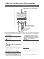
Mitsubishi Heavy Industries eco touch RC-EX1A Yükleme Rehberi
- Kategori
- Uzay ısıtıcıları
- Tip
- Yükleme Rehberi
Bu kılavuz için de uygundur

eco touch REMOTE CONTROL
RC-EX1A/RC-EX1N
INSTALLATION MANUAL
PJZ012D077
B
Sayfa yükleniyor ...
Sayfa yükleniyor ...
Sayfa yükleniyor ...
Sayfa yükleniyor ...
Sayfa yükleniyor ...
Sayfa yükleniyor ...
Sayfa yükleniyor ...
Sayfa yükleniyor ...
Sayfa yükleniyor ...
Sayfa yükleniyor ...
Sayfa yükleniyor ...

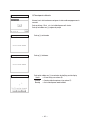
—
12
—
—
13
—
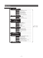
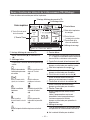
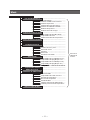
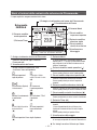
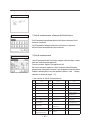
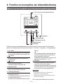
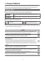
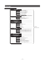
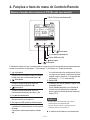
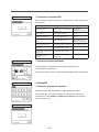
Main menu
R/C settings ( )
…………………………………………………………………… 20
Main/Sub of R/C ………………………………………………… 21
Return air temp…………………………………………………… 22
R/C sensor ……………………………………………………… 22
R/C sensor adjustment ………………………………………… 22
Operation mode ………………………………………………… 23
˚C / ˚F ……………………………………………………………… 23
Fan speed ………………………………………………………… 23
External input …………………………………………………… 24
Ventilation setting………………………………………………… 24
Flap control ……………………………………………………… 24
Auto-restart ……………………………………………………… 24
Auto temp setting………………………………………………… 25
Auto fan speed …………………………………………………… 25
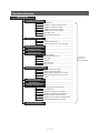
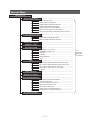
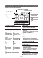
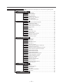
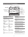
IU settings ( )
…………………………………………………………………… 26
High ceiling ……………………………………………………… 28
Filter sign ………………………………………………………… 29
External input 1…………………………………………………… 29
External input 1 signal …………………………………………… 29
External input 2…………………………………………………… 29
External input 2 signal …………………………………………… 29
Heating thermo-OFF temp adjustment ……………………… 30
Return air sensor adjustment…………………………………… 30
Fan control in cooling thermo-OFF …………………………… 30
Fan control in heating thermo-OFF …………………………… 30
Anti-frost temp …………………………………………………… 31
Anti-frost control ………………………………………………… 31
Drain pump operation …………………………………………… 31
Residual fan operation in cooling ……………………………… 31
Residual fan operation in heating ……………………………… 32
Intermittent fan operation in heating…………………………… 32
Fan circulator operation ………………………………………… 32
Control pressure adjust ………………………………………… 32
Auto operation mode …………………………………………… 33
Thermo. rule setting……………………………………………… 36
Auto fan speed control ………………………………………… 37
IU overload alarm………………………………………………… 37
…………………………………………………………………… 38
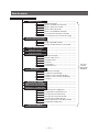
Service & Maintenance ( )
IU address ………………………………………………………… 39
Next service date ………………………………………………… 39
Operation data …………………………………………………… 40
Error display ……………………………………………………… 41
Saving IU settings ……………………………………………… 42
Special settings ………………………………………………… 44
…………………………………………………………………… 46
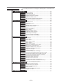
Select the language
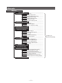
Installation settings ( )
…………………………………………………………………… 15
Installation date ………………………………………………… 16
Company information …………………………………………… 16
Test run …………………………………………………………… 17
Static pressure adjustment …………………………………… 18
Change auto-address …………………………………………… 18
Address setting of main IU ……………………………………… 18
IU back-up function ……………………………………………… 19
(
) It is necessary to input the Service password for menu items showing.
Sayfa yükleniyor ...
Sayfa yükleniyor ...

—
14
—
—
15
—
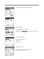
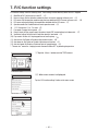
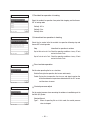
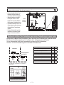
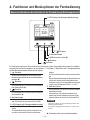
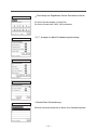
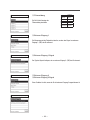
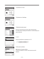
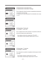
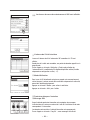
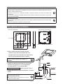
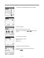
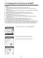
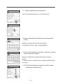
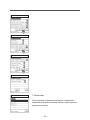
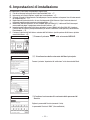
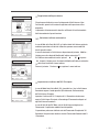
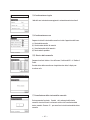
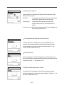
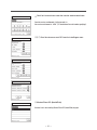
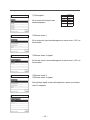
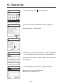
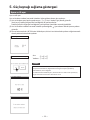
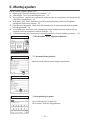
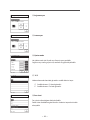
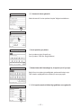
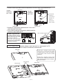
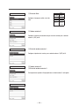
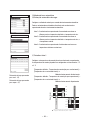
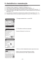
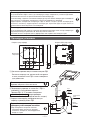
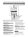
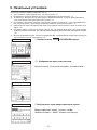
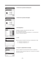
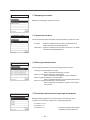
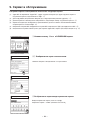
①
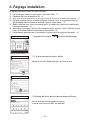
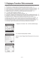
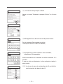
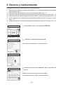
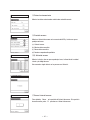
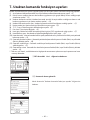
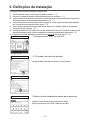
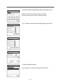
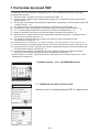
Tap the
Menu
button on the TOP screen.
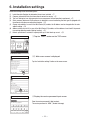
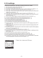
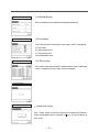
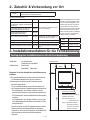
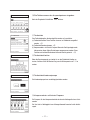
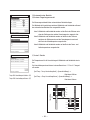
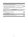
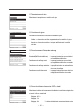
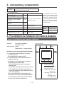
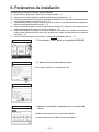
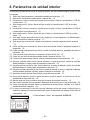
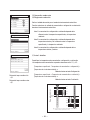
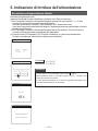
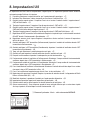
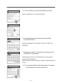
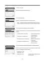
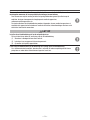
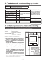
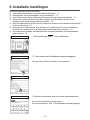
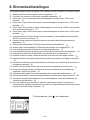
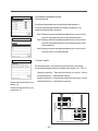
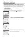
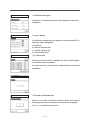
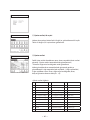
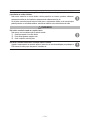
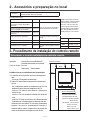
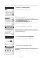
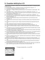
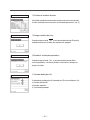
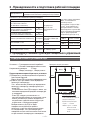
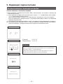
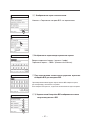
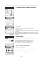
6. Installation settings
Installation settings cover the following items.
(1) Installation date: Register the date when the unit was installed. ➝
⑦
(2) Company information: Enter the information of contact for service. ➝
⑧
(3) Test run: Cooling test run, drain pump test run or compressor Hz fixed operation is performed. ➝
⑪
(4) Static pressure adjustment: Static pressure is adjusted in case of connecting the duct type IU equipped with
the external static pressure adjustment function. ➝
⑮
(5) Change auto-address: In case of the Multi Series (KX) models, the IU address can be changed after the auto-
address setting. ➝
⑯
(6) Address setting of main IU: In case of the Multi Series (KX) models, set the address of main/sub IU to prevent
from mixing operation modes (Cooling, heating). ➝
⑱
(7) IU back-up function: IU rotation, IU capacity back-up, IU fault back-up are set. ➝
⑲
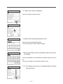
②③
Main menu screen is displayed.
Tap the “Installation settings” button on the menu screen.
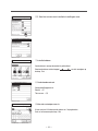
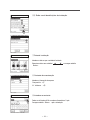
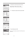
④
Display the service password input screen.
Enter the service password (4-digit number).
The service password is “9999”. (Unable to change)
①
TOP screen
②
Menu screen
③
Menu screen #2
④S
ervice password input
Sayfa yükleniyor ...

—
16
—
—
17
—
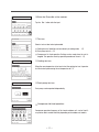
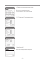
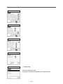
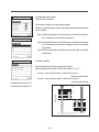
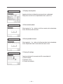
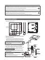
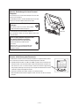
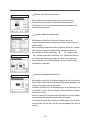
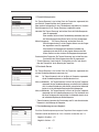
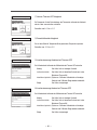
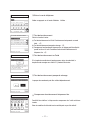
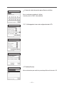
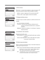
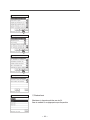
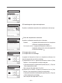
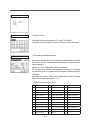
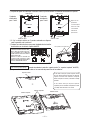
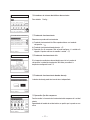
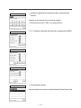
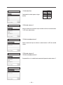
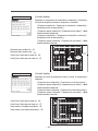
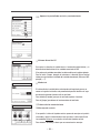
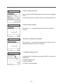
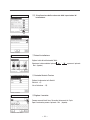
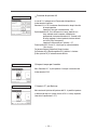
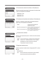
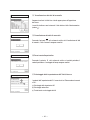
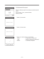
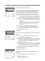
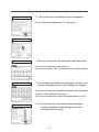
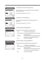
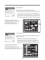
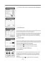
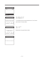
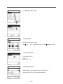
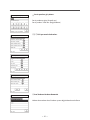
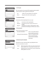
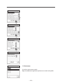
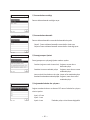
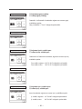
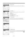
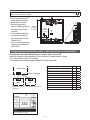
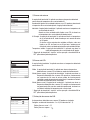
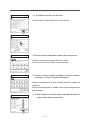
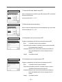
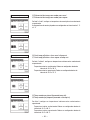
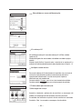
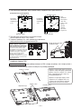
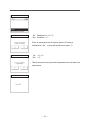
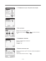
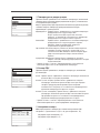
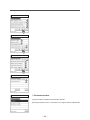
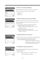
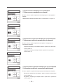
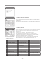
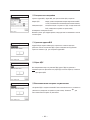
⑩
Enter the Phone No. of the contact.
Tap the
Set
button after the input.
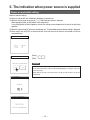
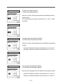
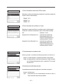
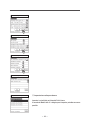
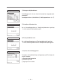
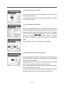
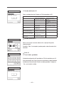
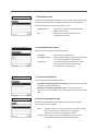
⑪
Test run
Select a test run item to be implemented.
(a) Cooling test run: Operation can be made only in cooling mode. ➝
⑫
(b) Drain pump test run ➝
⑬
(c) Compressor Hz fixed operation: Setting can be made when the unit is
stopped. This operation starts by operation procedure of the unit. ➝
⑭
⑩
Enter the Phone No. of the contact
⑪
Test run
12
13
14
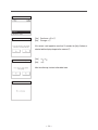
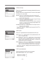
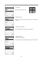
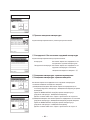
⑫
Cooling test run
When the room temperature is too low to start the cooling test run, it operates
for 30 minutes by decreasing the set temperature to 5°C.
⑬
Drain pump test run
Drain pump can be operated independently.
⑭
Compressor Hz fixed operation
Compressor operation frequency of the inverter outdoor unit can be fixed. It
may not be able to control effectively depending on the outdoor unit models.
⑫
Cooling test run
⑬
Drain pump test run
⑭
Compressor Hz xed operation

—
18
—
—
19
—
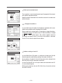
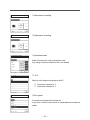
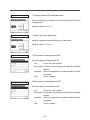
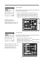
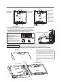
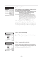
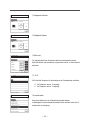
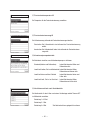
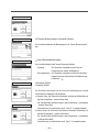
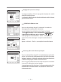
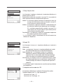
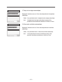
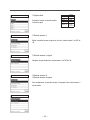
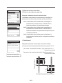
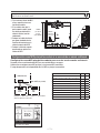
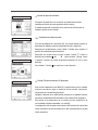
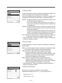
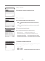
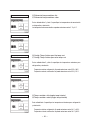
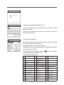
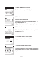
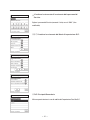
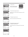
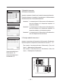
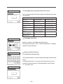
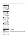
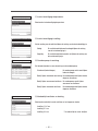
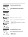
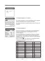
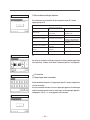
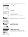
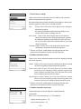
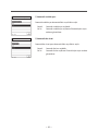
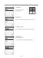
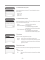
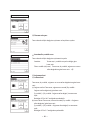
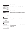
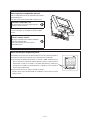
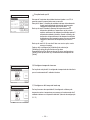
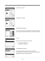
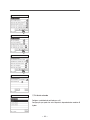
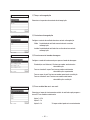
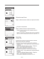
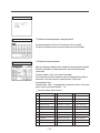
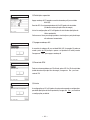
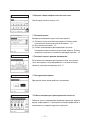
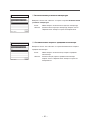
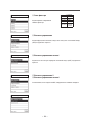
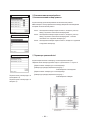
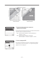
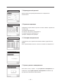
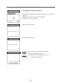
⑮
Static pressure adjustment
This is operable in case of connecting duct type IU equipped with the external
static pressure adjustment function.
Operating method is described in the installation manuals for the indoor units
with this function.
⑮
Static pressure adjustment
⑯⑰
Change auto-address
In case of Multi series (KX) models, the IU addresses registered with the auto-
address setting method can be changed with this function .
When an indoor unit is selected and the
Change
button is tapped, the display
changes to the Change auto-address screen
⑰
. When the address is changed
with
▲ ▼
buttons and the
Set
button is tapped, it returns to
the Change auto-address screen
⑯
on which the new address is displayed.
Tap the
Finish
button to register the new address.
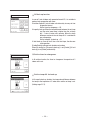
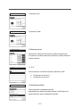
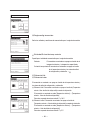
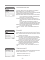
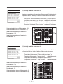
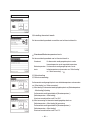
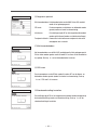
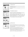
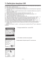
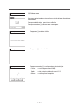
⑱
Address setting of main IU
In case of Multi Series (KX) models, it is possible to let indoor units (Sub IUs)
follow the operation mode (Heating, cooling) of the indoor unit (Main IU).
Set the address of the Main IU to the Sub IUs which shall be followed to the
Main IU by using each R/C connected to each Sub IU.
In case of the single PAC unit, or the plural indoor units connected to one R/C,
it is not available to operate.
Setting can be made from the main R/C of Sub IU only. It cannot be set from
the sub R/C of Sub IU.
⑯
Change auto-address
⑰
Change auto-address
⑱
Address setting of main IU
Sayfa yükleniyor ...
Sayfa yükleniyor ...
Sayfa yükleniyor ...

—
22
—
—
23
—
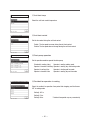
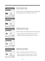
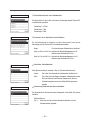
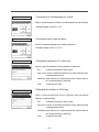
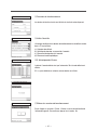
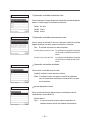
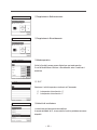
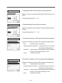
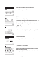
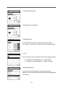
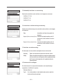
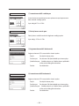
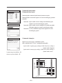
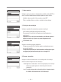
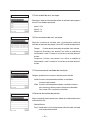
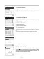
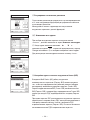
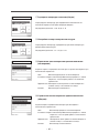
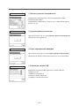
⑨
Return air temp
Thermo. rule* is applied based on the temperature detected with the return air
temp sensor of IU.
When plural indoor units are connected to one R/C, the return air temp applied
to the thermo. rule* can be selected.
Individual: Thermo. rule* is applied based on the return air temp of each IU.
When plural units are connected to one R/C, it is based on the
return air temp of the main unit.
Master IU: Thermo. rule* is applied based on the return air temp of IU having
the youngest address out of IUs connected.
If there are several sets of plural units each of which is connected
to one R/C, it is based on the IU having the youngest address out of
the main units of each plural units.
Averaged temp: Thermo. rule* is applied based on the average of return air
temperatures of IUs connected.
* “Thermo. rule” means the “Judging to make thermostat ON or OFF” by
detecting temperature.
⑩
R/C sensor
Thermo. rule* is applied based on the temp detected with the R/C sensor.
Enable: Thermo. rule* is applied based on the temp detected with the R/C
sensor in all operation modes.
Enable (Heating only): Thermo. rule* is applied based on the temp detected
with the R/C sensor in heating operation only. In case of other
operation modes (including auto-heating mode), it is based on the
Individual control of return air temperature.
Enable (Cooling only): Thermo. rule* is applied based on the temp detected
with the R/C sensor, excepted in heating operation. In case of heating
modes, it is based on the Individual control of return air temperature.
* “Thermo. rule” means the “Judging to make thermostat ON or OFF” by
detecting temperature.
⑩
R/C sensor
⑨
Return air temp
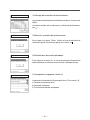
⑪
R/C sensor adjustment
Temperatures detected with the R/C sensor can be adjusted.
Set this within the range of -3 to +3. (At 1°C intervals)
Adjustment in cooling ➝
⑫
Adjustment in heating ➝
⑬
⑪
R/C sensor adjustment
12
13
Sayfa yükleniyor ...

—
24
—
—
25
—
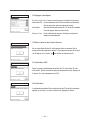
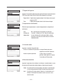
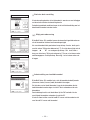
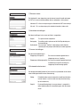
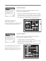
⑰
External input
Set the range to apply the external input received through CNT of either one IU
to plural indoor units connected in one system
Individual: This is applied only to the IU receiving CNT input.
All units: This is applied to all indoor units connected.
⑱
Ventilation setting
Set this when a ventilation device is connected.
Disable: No ventilation device is connected.
Interlocking: Ventilation is interlocked with the Run/Stop of air conditioner.
Independent: If the ventilation is selected from the menu, only the
ventilation device is operated or stopped independently.
⑰
External input
⑱
Ventilation setting
⑲
Flap control
Set the flap stop control.
Stop at fixed position: The flap can be set to stop at one of 4 positions.
Stop at any position: The flap can be set to stop at any position
immediately after operating the R/C switch.
⑳
Auto-restart
Set the state of operation to be started when the power supply is restored
after a power failure.
Enable: It returns to the state before the power failure as soon as the
power supply is restored (After the end of the primary control at
the power on).
Disable: It stops after the restoration of power supply, regardless the state
of operation before the power failure.
⑲
Flap control
⑳
Auto-restart
Sayfa yükleniyor ...
Sayfa yükleniyor ...
Sayfa yükleniyor ...
Sayfa yükleniyor ...

—
28
—
—
29
—
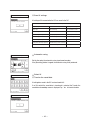
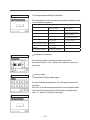
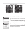
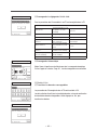
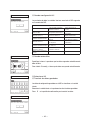
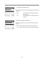
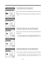
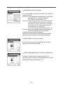
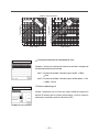
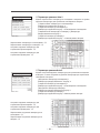
⑫
Filter sign
Set the time to display the filter sign.
⑬
External input 1
Set the control at the time when the signal is input to the external input 1
(CNT) of IU.
⑫
Filter sign
⑬
External input 1
Standard
No display None
Setting 1 180Hr
Setting 2 600Hr
Setting 3 1,000Hr
Setting 4
1,000Hr
Operation stop
⑭
External input 1 signal
Set the signal type to input to the external input 1 (CNT) of IU.
⑮
External input 2
⑯
External input 2 signal
This is operable when the IU equipped with the external input 2 is connected.
⑭
External input 1 signal
⑮
External input 2
⑯
External input 2 signal

—
30
—
—
31
—
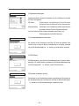
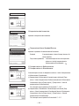
⑰
Heating thermo-OFF temp adjustment
Adjust the temperature for judging to make thermostat ON or OFF during
heating operation.
Adjustable range is 0°C to +3°C.
⑰
Heating thermo-OFF temp adjustment
⑳
Fan control in heating thermo-OFF
Set the fan speed at the heating thermo-OFF.
Low: The fan runs at the low speed.
Set fan speed: The fan runs at the same speed as that during the thermo-ON
operation.
Intermittent: Cycles of Lo fan operation for 2 minutes and stop for 5 minutes
are repeated.
Stop: The fan is stopped.
⑲
Fan control in cooling thermo-OFF
Set the fan speed at the cooling thermo-OFF.
Low: The fan runs at the low speed.
Set fan speed: The fan runs at the same speed as that during the thermo-ON
operation.
Intermittent: Cycles of Lo fan operation for 2 minutes and stop for 5 minutes
are repeated.
Stop: The fan is stopped.
⑱
Return air sensor adjustment
Adjust the temperature detected with the return air temp sensor.
Adjustable range is -2°C to +2°C.
⑱
Return air sensor adjustment
⑲
Fan control in cooling thermo-OFF
⑳
Fan control in heating thermo-OFF
Sayfa yükleniyor ...
Sayfa yükleniyor ...
Sayfa yükleniyor ...
Sayfa yükleniyor ...
Sayfa yükleniyor ...
Sayfa yükleniyor ...
Sayfa yükleniyor ...

—
38
—
—
39
—
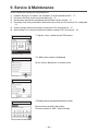
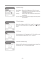
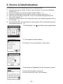
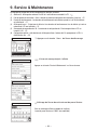
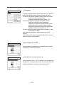
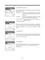
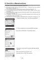
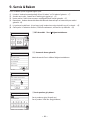
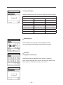
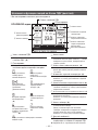
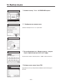
9. Service & Maintenance
Service & Maintenance settings cover the following items.
(1) IU address: Displays the “IU address” and “OU address” of the IU connected to the R/C. ➝
⑦
(2) Next service date: Enter the next service date (dd/mm/yy). ➝
⑨
(3) Operation data: Operation data are displayed when the indoor unit No is selected. ➝
⑪
(4) Error display: Error history and the data at occurrence of error, which are in the memory of R/C, are displayed.
➝
⑭
(5) Saving IU settings: Contents of IU settings are saved in the R/C or transferred to IU. ➝
(6) Special settings: This is used for the erasing of IU address, resetting of CPU, initializing, etc. ➝
①
Tap the
Menu
button on the TOP screen.
②③
Main menu screen is displayed.
Tap the “Service & Maintenance” on the menu screen.
①
TOP screen
②
Menu screen 1
③
Menu screen 3
④
Display the service password input screen.
Enter the service password (4-digit number).
The service password is “9999”. (Unable to change)
④
Service password input
Sayfa yükleniyor ...
Sayfa yükleniyor ...

—
40
—
—
41
—
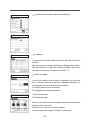
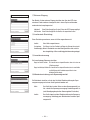
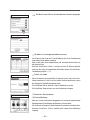
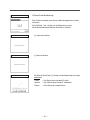
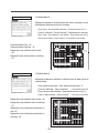
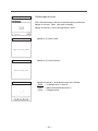
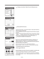
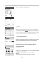
⑬
Individual display
Data of selected items are updated and displayed automatically.
⑬
Individual display
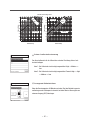
⑭
Error display
Error history and data at occurrence of error saved in the R/C are displayed.
(a) Error history
(b) Display anomaly data
(c) Erase anomaly data
(d) Reset periodical check
⑮⑯
Error history
Date and time when error occurred, IU address and Error Code are displayed.
If none is recorded in the error history, no error is displayed.
⑰
Delete error history
If the
Delete
button on the Error history screen is tapped, the Delete error
history acknowledge screen is displayed. Tap
Yes
to erase the display of
error history.
⑭
Error display
⑮
Error history
⑯
No error display
⑰
Delete error history
15
18
19
20

—
42
—
—
43
—
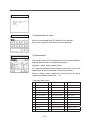
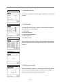
⑱
Display anomaly data
Operation data taken just before the occurrence of error are displayed.
Display items are same as the <Operation data items> (refer to
⑫
).
⑲
Erase anomaly data
When tapping the
Yes
button on the Erase anomaly data acknowledge
screen, the anomaly data are erased.
Saving IU settings
Contents of setting for IU are saved in the R/C or transmitted to IU.
(a) Save IU settings
(b) Automatic saving
(c) Transfer the saved data
⑳
Reset periodical check
When tapping the
Yes
button on the Reset periodical check acknowledge
screen, the periodical check is reset and the time count is reset.
⑱
Display anomaly data
⑲
Erase anomaly data
⑳
Reset periodical check
Saving IU settings
22
23
25
Sayfa yükleniyor ...

—
44
—
—
45
—
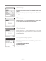
Special settings
Erase IU address: Memory of the IU address for multi (KX) unit is erased.
CPU reset: Microcomputers of IU and OU connected are reset (State
of restoration after power failure).
Initializing: Settings on R/C and IU connected are initialized (State of
factory default).
Touch panel calibration
: Use this to correct when the display and the touch position
are not matched.
Restore of default setting
Settings on the R/C and IU connected are restored to the default setting (State
of factory default). Tap
Yes
to restore the default setting.
CPU reset
All microcomputers on the R/C operated, other R/Cs, IUs and OUs are reset
(State of restoration after power failure). Tap
Yes
to reset CPU
Erase IU address
Memory of the IU address for Multi (KX) unit is erased. This is operable from
the main R/C only and only when IUs are stopped. Tap
Yes
to erase IU
address
Special settings
Erase IU address
CPU reset
Restore of default setting
27
28
29
30
Sayfa yükleniyor ...

—
46
—
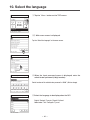
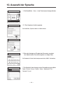
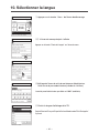
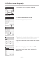
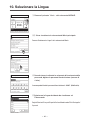
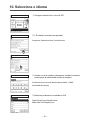
10. Select the language
①
Tap the
Menu
button on the TOP screen.
②③
Main menu screen is displayed.
Tap the “Select the language” on the menu screen.
④
When the Input password screen is displayed, enter the
administrator password (4-digit number).
Default number of the administrator password is “0000”. (Able to change)
④
Service password input
①
TOP screen
②
Menu screen
③
Menu screen #2
⑤
Select the language to be displayed on the R/C.
English / Deutsch / Français / Espanõl / Italiano /
Nederlandse / Türk / Português /
Русский
⑤
Select the language
Sayfa yükleniyor ...

—
1
—
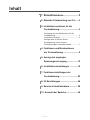
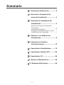
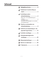
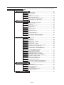
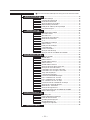
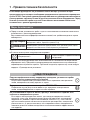
Inhalt
1. Safety Precautions …………………2
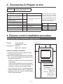
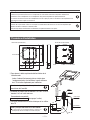
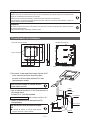
2. Accessories & Prepare on site ……4
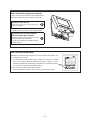
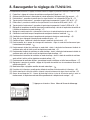
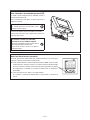
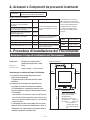
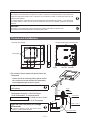
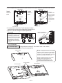
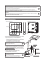
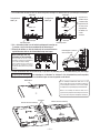
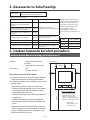
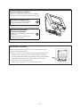
3. Remote control installation
procedure …………………………… 4
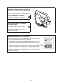
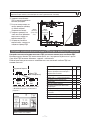
Determine where to install the remote control
.. 4
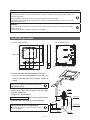
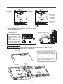
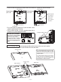
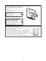
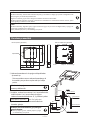
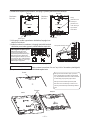
Installation procedure …………………………… 5
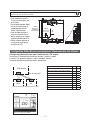
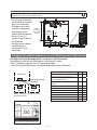
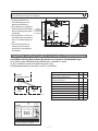
Main/Sub setting when more than one remote
controls are used ………………………………… 7
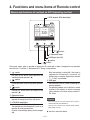
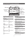
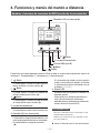
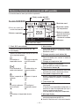
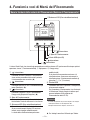
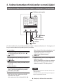
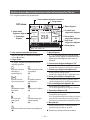
4. Functions and menu items of
Remote control ………………………9
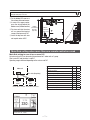
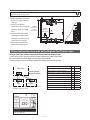
5. The indication when power source
is supplied ………………………… 13
6. Installation settings ……………… 15
7. R/C function settings …………… 20
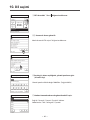
8. IU settings ………………………… 26
9. Service & Maintenance ………… 38
10. Select the Language …………… 46
1. Sicherheitshinweise ..........................2
2. Zubehör & Vorbereitung vor Ort .......4
3. Installationsverfahren für die
Fernbedienung ..................................4
Festlegung des Installationsortes für die
Fernbedienung ...................................................4
Installationsverfahren .........................................5
Konfiguration als Master-/Slave-
Fernbedienung, wenn mehrere
Fernbedienungen verwendet werden ...............7
4. Funktionen und Menüoptionen
der Fernbedienung ...........................9
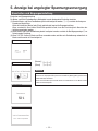
5. Anzeige bei angelegter
Spannungsversorgung ...................13
6. Installationseinstellungen .............. 15
7. Funktionseinstellungen der
Fernbedienung ................................20
8. IG-Einstellungen ..............................26
9. Service & Inbetriebnahme ..............38
10. Auswahl der Sprache ....................46

—
2
—
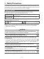
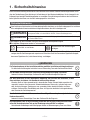
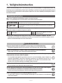
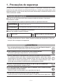
1 . Sicherheitshinweise
Diese Installationsanleitung beschreibt das Installationsverfahren und die Sicherheitsvorkehrungen bei der Install-
ation der Fernbedienung. Diese Anleitung ist in Verbindung mit den Benutzerhandbüchern für das Innengerät, das
Außengerät und sonstige Zubehörkomponenten zu verwenden. Diese Anleitung vor Aufnahme der Installationsar-
beiten gründlich durchlesen, um das Gerät ordnungsgemäß zu installieren.
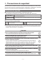
Sicherheitshinweise
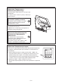
●
Diese Anleitung vor Aufnahme der Installationsarbeiten gründlich durchlesen, um das Gerät ordnungsgemäß zu installieren.
Alle nachfolgenden Hinweise enthalten wichtige Informationen, die strikt zu befolgen sind.
WARNUNG
Die Nichtbefolgung oder unzureichende Befolgung dieser Hinweise kann schwerwiegende
Konsequenzen haben, wie etwa tödliche Unfälle, schwere Verletzungen usw.
VORSICHT
Die Nichtbefolgung oder unzureichende Befolgung dieser Hinweise kann zu Verletzungen
oder Sachschäden führen.
In Abhängigkeit von den Umständen sind auch schwerwiegende Konsequenzen möglich.
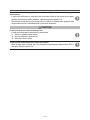
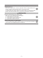
●
Die folgenden Piktogramme werden im Text verwendet.
Keinesfalls so verfahren.
Grundsätzlich die Anweisungen
befolgen.
●
Diese Anleitung an einem sicheren Ort aufbewahren, wo sie jederzeit zugänglich ist. Diese Anleitung dem Monteur
vorlegen, der das Gerät bewegen oder reparieren soll. Wenn das Gerät an einen anderen Eigentümer übergeht,
dem neuen Eigentümer die „Installationsanleitung“ aushändigen.
WARNUNG
Ein Fachunternehmen mit den Installationsarbeiten gemäß der Installationsanleitung beauftragen.
Die fehlerhafte Ausführung der Installation kann zu Stromschlag, Feuer oder Geräteausfällen führen.
Vor Aufnahme von Arbeiten an der Elektrik die Netzspannungsversorgung ausschalten.
Andernfalls können Stromschläge, Geräteausfälle oder Funktionsstörungen die Folge sein.
Das Gerät keinesfalls in einer ungeeigneten Umgebung oder an einem Ort installieren, an dem
Gase entstehen, einströmen, sich ansammeln oder austreten können.
Wenn das Gerät an Orten verwendet wird, in denen dichter Ölnebel, Dämpfe, Nebel organischer Lös-
ungsmittel, korrosive Gase (Ammoniak, Schwefelverbindungen, Säuren usw.) auftreten oder saure
oder alkalische Lösungen, Spezialsprays usw. verwendet werden, besteht die Gefahr von Strom-
schlägen, Geräteausfällen, Rauchbildung oder Feuer als Folge einer deutlichen Leistungsminderung
oder Korrosion der Gerätekomponenten.
Das Gerät nicht an Orten installieren, an denen übermäßiger Wasserdampf erzeugt wird oder
Kondensation auftritt.
Andernfalls können Stromschläge, Feuer oder Geräteausfälle die Folge sein.
Die angegebenen Kabel für die Verdrahtung verwenden und sorgfältig sichere Anschlüsse hers-
tellen, um die elektronischen Teile vor der Einwirkung externer Kräfte zu schützen.
Unzureichende Verbindungen oder Befestigungen können zu Wärmeerzeugung, Feuer usw. führen.
Sayfa yükleniyor ...
Sayfa yükleniyor ...
Sayfa yükleniyor ...
Sayfa yükleniyor ...
Sayfa yükleniyor ...
Sayfa yükleniyor ...
Sayfa yükleniyor ...
Sayfa yükleniyor ...
Sayfa yükleniyor ...
Sayfa yükleniyor ...
Sayfa yükleniyor ...
Sayfa yükleniyor ...

—
15
—
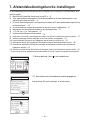
①
Die Schaltfläche
Menu
in der Touchscreen-Anzeige drücken.
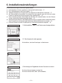
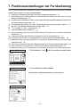
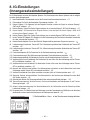
6. Installationseinstellungen
Die Installationseinstellungen umfassen die folgenden Optionen.
(1) Installationsdatum: Das Datum registrieren, an dem das Gerät installiert wurde. ➝
⑦
(2) Firma: Die Kontaktdaten für den Service eingeben. ➝
⑧
(3) Testbetrieb: Cooling test run, drain pump test run or compressor Hz fixed operation is performed. ➝
⑪
(4) Stat. Zieldruck Abgl. bei Aussenluftbetr.: Der statische Druck wird angepasst, sofern ein IG mit Kanal und der
Funktion zur Anpassung des externen statischen Drucks angeschlossen ist. ➝
⑮
(5) Autom. Adressierung aendern: Sofern Modelle der Multi-Serie (KX) verwendet werden, kann die IG-Adresse
nach der automatischen Adressierung geändert werden. ➝
⑯
(6)
Adresseinstellung des Master-IG: Sofern Modelle der Multi-Serie (KX) verwendet werden, die Adresse des Master/
Slave-IG zuweisen, um eine Verwechslung der Betriebsarten (Kühlbetrieb/Heizbetrieb) zu vermeiden.
➝
⑱
(7) IG Back-Up-Funktion: IU rotation, IU capacity back-up, IU fault back-up werden hier eingestellt. ➝
⑲
②③
Das Hauptmenü wird angezeigt.
Die Schaltfläche „Installation-Einstellungen“ im Menü drücken.
④
Die Anzeige zur Eingabe des Service-Passworts erscheint.
Das Service-Passwort eingeben (4-stellige Zahl).
Das Service-Passwort lautet „9999“. (Nicht veränderbar)
①
Touchscreen-Anzeige
②
Menü-Bildschirm
③
Menü-Bildschirm #2
④
Service-Passworteingeben
Sayfa yükleniyor ...
Sayfa yükleniyor ...
Sayfa yükleniyor ...
Sayfa yükleniyor ...
Sayfa yükleniyor ...
Sayfa yükleniyor ...
Sayfa yükleniyor ...
Sayfa yükleniyor ...
Sayfa yükleniyor ...
Sayfa yükleniyor ...
Sayfa yükleniyor ...
Sayfa yükleniyor ...
Sayfa yükleniyor ...

—
29
—
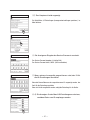
⑫
Filtermeldung
Die Zeit für die Anzeige der
Filtermeldung einstellen.
⑬
Externer Eingang 1
Die Steuerung auf den Zeitpunkt einstellen, an dem das Signal am externen
Eingang 1 (CNT) des IG ankommt.
⑫
Filtermeldung
⑬
Externer Eingang 1
Standard
Keine
Anzeige
Keiner
Einstellung 1
180Std.
Einstellung
2 600Std.
Einstellung
3 1,000Std.
Einstellung
4
1,000Std.
Stopp-Betrieb
⑭
Externer Eingang 1 Signal
Den Typ des Signals festlegen, das am externen Eingang 1 (CNT) des IG ankommt.
⑮
Externer Eingang 2
⑯
Externer Eingang 2 Signal
Diese Funktion ist aktiv, wenn das IG mit externem Eingang 2 angeschlossen ist.
⑭
Externer Eingang 1 Signal
⑮
Externer Eingang 2
⑯
Externer Eingang 2 Signal
Sayfa yükleniyor ...
Sayfa yükleniyor ...
Sayfa yükleniyor ...
Sayfa yükleniyor ...
Sayfa yükleniyor ...
Sayfa yükleniyor ...
Sayfa yükleniyor ...
Sayfa yükleniyor ...

—
38
—
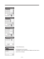
9. Service & Inbetriebnahme
Die Einstellungen unter Service & Inbetriebnahme umfassen die folgenden Optionen.
(1) Innengeraeteadressnummer: Zeigt die „IG-Adresse“ und die „AG-Adresse“ für das mit der Fernbedienung
verbundene IG an. ➝
⑦
(2) Naechstes Servicedatum: Das nächste Servicedatum eingeben (TT/MM/JJ). ➝
⑨
(3) Betriebsdaten: Die Betriebsdaten werden angezeigt, wenn die Innengeräte-Nr. gewählt wird. ➝
⑪
(4) Fehleranzeige: Die Fehlerhistorie und das Datum, an dem ein in der Fernbedienung gespeicherter Fehler
auftrat, werden angezeigt.➝
⑭
(5) Innengeraeteeinstellungen speichern: Die IG-Einstellungen werden in der Fernbedienung gespeichert oder an
das IG übertragen. ➝
(6) Spezialeinstellungen: Unter dieser Option können IG-Adressen gelöscht, die CPU zurückgesetzt, die Initialisier-
ung durchgeführt werden usw. ➝
①
Die Schaltfläche
Menu
in der Touchscreen-Anzeige drücken.
②③
Das Hauptmenü wird angezeigt.
Die Schaltfläche „Service & Inbetriebnahme“ im Menü drücken.
①
Touchscreen-Anzeige
②
Menü-Bildschirm 1
③
Menü-Bildschirm 3
④
Die Anzeige zur Eingabe des Service-Passworts erscheint.
Das Service-Passwort eingeben (4-stellige Zahl).
Das Service-Passwort lautet „9999“. (Nicht veränderbar)
④
Service-Passwort eingeben
Sayfa yükleniyor ...
Sayfa yükleniyor ...

—
41
—
⑬
Individuelle Anzeige
Die Daten der ausgewählten Optionen werden automatisch aktualisiert und
angezeigt.
⑬
Individuelle Anzeige
⑭
Fehleranzeige
Die Fehlerhistorie und das Datum, an dem ein in der Fernbedienung gespeich-
erter Fehler auftrat, werden angezeigt.
(a) Fehlerhistorie
(b) Fehler-Betriebsdaten
(c) Loeschen Fehlerbetriebsdaten
(d) Reset Pruefintervall
⑮⑯
Fehlerhistorie
Datum und Uhrzeit des Fehlers, IG-Adresse und Fehlercode werden angezeigt.
Wenn die Fehlerhistorie keine derartigen Einträge enthält, wird kein Fehler
angezeigt.
⑰
Fehlerhistorie loeschen
Wenn die Schaltfläche
Loeschen in der Anzeige der Fehlerhistorie gedrückt
wird, erscheint die Bestätigungsanzeige zum loeschen der Fehlerhistorie.
Ja
drücken, um die Anzeige der Fehlerhistorie zu loeschen.
⑭
Fehleranzeige
⑮
Fehlerhistorie
⑯
Fehlerhistorie
⑰
Fehlerhistorie loeschen
15
18
19
20
Sayfa yükleniyor ...
Sayfa yükleniyor ...
Sayfa yükleniyor ...
Sayfa yükleniyor ...
Sayfa yükleniyor ...
Sayfa yükleniyor ...
Sayfa yükleniyor ...
Sayfa yükleniyor ...
Sayfa yükleniyor ...
Sayfa yükleniyor ...
Sayfa yükleniyor ...
Sayfa yükleniyor ...
Sayfa yükleniyor ...
Sayfa yükleniyor ...
Sayfa yükleniyor ...
Sayfa yükleniyor ...
Sayfa yükleniyor ...
Sayfa yükleniyor ...
Sayfa yükleniyor ...
Sayfa yükleniyor ...
Sayfa yükleniyor ...
Sayfa yükleniyor ...
Sayfa yükleniyor ...
Sayfa yükleniyor ...
Sayfa yükleniyor ...
Sayfa yükleniyor ...
Sayfa yükleniyor ...
Sayfa yükleniyor ...
Sayfa yükleniyor ...
Sayfa yükleniyor ...
Sayfa yükleniyor ...
Sayfa yükleniyor ...
Sayfa yükleniyor ...
Sayfa yükleniyor ...
Sayfa yükleniyor ...
Sayfa yükleniyor ...
Sayfa yükleniyor ...
Sayfa yükleniyor ...
Sayfa yükleniyor ...
Sayfa yükleniyor ...
Sayfa yükleniyor ...
Sayfa yükleniyor ...
Sayfa yükleniyor ...
Sayfa yükleniyor ...
Sayfa yükleniyor ...
Sayfa yükleniyor ...
Sayfa yükleniyor ...
Sayfa yükleniyor ...
Sayfa yükleniyor ...
Sayfa yükleniyor ...
Sayfa yükleniyor ...
Sayfa yükleniyor ...
Sayfa yükleniyor ...
Sayfa yükleniyor ...
Sayfa yükleniyor ...
Sayfa yükleniyor ...
Sayfa yükleniyor ...
Sayfa yükleniyor ...
Sayfa yükleniyor ...
Sayfa yükleniyor ...
Sayfa yükleniyor ...
Sayfa yükleniyor ...
Sayfa yükleniyor ...
Sayfa yükleniyor ...
Sayfa yükleniyor ...
Sayfa yükleniyor ...
Sayfa yükleniyor ...
Sayfa yükleniyor ...
Sayfa yükleniyor ...
Sayfa yükleniyor ...
Sayfa yükleniyor ...
Sayfa yükleniyor ...
Sayfa yükleniyor ...
Sayfa yükleniyor ...
Sayfa yükleniyor ...
Sayfa yükleniyor ...
Sayfa yükleniyor ...
Sayfa yükleniyor ...
Sayfa yükleniyor ...
Sayfa yükleniyor ...
Sayfa yükleniyor ...
Sayfa yükleniyor ...
Sayfa yükleniyor ...
Sayfa yükleniyor ...
Sayfa yükleniyor ...
Sayfa yükleniyor ...
Sayfa yükleniyor ...
Sayfa yükleniyor ...
Sayfa yükleniyor ...
Sayfa yükleniyor ...
Sayfa yükleniyor ...
Sayfa yükleniyor ...
Sayfa yükleniyor ...
Sayfa yükleniyor ...
Sayfa yükleniyor ...
Sayfa yükleniyor ...
Sayfa yükleniyor ...
Sayfa yükleniyor ...
Sayfa yükleniyor ...
Sayfa yükleniyor ...
Sayfa yükleniyor ...
Sayfa yükleniyor ...
Sayfa yükleniyor ...
Sayfa yükleniyor ...
Sayfa yükleniyor ...
Sayfa yükleniyor ...
Sayfa yükleniyor ...
Sayfa yükleniyor ...
Sayfa yükleniyor ...
Sayfa yükleniyor ...
Sayfa yükleniyor ...
Sayfa yükleniyor ...
Sayfa yükleniyor ...
Sayfa yükleniyor ...
Sayfa yükleniyor ...
Sayfa yükleniyor ...
Sayfa yükleniyor ...
Sayfa yükleniyor ...
Sayfa yükleniyor ...
Sayfa yükleniyor ...
Sayfa yükleniyor ...
Sayfa yükleniyor ...
Sayfa yükleniyor ...
Sayfa yükleniyor ...
Sayfa yükleniyor ...
Sayfa yükleniyor ...
Sayfa yükleniyor ...
Sayfa yükleniyor ...
Sayfa yükleniyor ...
Sayfa yükleniyor ...
Sayfa yükleniyor ...
Sayfa yükleniyor ...
Sayfa yükleniyor ...
Sayfa yükleniyor ...
Sayfa yükleniyor ...
Sayfa yükleniyor ...
Sayfa yükleniyor ...
Sayfa yükleniyor ...
Sayfa yükleniyor ...
Sayfa yükleniyor ...
Sayfa yükleniyor ...
Sayfa yükleniyor ...
Sayfa yükleniyor ...
Sayfa yükleniyor ...
Sayfa yükleniyor ...
Sayfa yükleniyor ...
Sayfa yükleniyor ...
Sayfa yükleniyor ...
Sayfa yükleniyor ...
Sayfa yükleniyor ...
Sayfa yükleniyor ...
Sayfa yükleniyor ...
Sayfa yükleniyor ...
Sayfa yükleniyor ...
Sayfa yükleniyor ...
Sayfa yükleniyor ...
Sayfa yükleniyor ...
Sayfa yükleniyor ...
Sayfa yükleniyor ...
Sayfa yükleniyor ...
Sayfa yükleniyor ...
Sayfa yükleniyor ...
Sayfa yükleniyor ...
Sayfa yükleniyor ...
Sayfa yükleniyor ...
Sayfa yükleniyor ...
Sayfa yükleniyor ...
Sayfa yükleniyor ...
Sayfa yükleniyor ...
Sayfa yükleniyor ...
Sayfa yükleniyor ...
Sayfa yükleniyor ...
Sayfa yükleniyor ...
Sayfa yükleniyor ...
Sayfa yükleniyor ...
Sayfa yükleniyor ...
Sayfa yükleniyor ...
Sayfa yükleniyor ...
Sayfa yükleniyor ...
Sayfa yükleniyor ...
Sayfa yükleniyor ...
Sayfa yükleniyor ...
Sayfa yükleniyor ...
Sayfa yükleniyor ...
Sayfa yükleniyor ...
Sayfa yükleniyor ...
Sayfa yükleniyor ...
Sayfa yükleniyor ...
Sayfa yükleniyor ...
Sayfa yükleniyor ...
Sayfa yükleniyor ...
Sayfa yükleniyor ...
Sayfa yükleniyor ...
Sayfa yükleniyor ...
Sayfa yükleniyor ...
Sayfa yükleniyor ...
Sayfa yükleniyor ...
Sayfa yükleniyor ...
Sayfa yükleniyor ...
Sayfa yükleniyor ...
Sayfa yükleniyor ...
Sayfa yükleniyor ...
Sayfa yükleniyor ...
Sayfa yükleniyor ...
Sayfa yükleniyor ...
Sayfa yükleniyor ...
Sayfa yükleniyor ...
Sayfa yükleniyor ...
Sayfa yükleniyor ...
Sayfa yükleniyor ...
Sayfa yükleniyor ...
Sayfa yükleniyor ...
Sayfa yükleniyor ...
Sayfa yükleniyor ...
Sayfa yükleniyor ...
Sayfa yükleniyor ...
Sayfa yükleniyor ...
Sayfa yükleniyor ...
Sayfa yükleniyor ...
Sayfa yükleniyor ...
Sayfa yükleniyor ...
Sayfa yükleniyor ...
Sayfa yükleniyor ...
Sayfa yükleniyor ...
Sayfa yükleniyor ...
Sayfa yükleniyor ...
Sayfa yükleniyor ...
Sayfa yükleniyor ...
Sayfa yükleniyor ...
Sayfa yükleniyor ...
Sayfa yükleniyor ...
Sayfa yükleniyor ...
Sayfa yükleniyor ...
Sayfa yükleniyor ...
Sayfa yükleniyor ...
Sayfa yükleniyor ...
Sayfa yükleniyor ...
Sayfa yükleniyor ...
Sayfa yükleniyor ...
Sayfa yükleniyor ...
Sayfa yükleniyor ...
Sayfa yükleniyor ...
Sayfa yükleniyor ...
Sayfa yükleniyor ...
Sayfa yükleniyor ...
Sayfa yükleniyor ...
Sayfa yükleniyor ...
Sayfa yükleniyor ...
Sayfa yükleniyor ...
Sayfa yükleniyor ...
Sayfa yükleniyor ...
Sayfa yükleniyor ...
Sayfa yükleniyor ...
Sayfa yükleniyor ...
Sayfa yükleniyor ...
Sayfa yükleniyor ...
Sayfa yükleniyor ...
Sayfa yükleniyor ...
Sayfa yükleniyor ...
Sayfa yükleniyor ...
Sayfa yükleniyor ...
Sayfa yükleniyor ...
Sayfa yükleniyor ...
Sayfa yükleniyor ...
Sayfa yükleniyor ...
Sayfa yükleniyor ...
Sayfa yükleniyor ...
Sayfa yükleniyor ...
Sayfa yükleniyor ...
Sayfa yükleniyor ...
Sayfa yükleniyor ...
Sayfa yükleniyor ...
Sayfa yükleniyor ...
Sayfa yükleniyor ...
Sayfa yükleniyor ...
Sayfa yükleniyor ...
Sayfa yükleniyor ...
Sayfa yükleniyor ...
Sayfa yükleniyor ...
Sayfa yükleniyor ...
Sayfa yükleniyor ...
Sayfa yükleniyor ...
Sayfa yükleniyor ...
Sayfa yükleniyor ...
Sayfa yükleniyor ...
Sayfa yükleniyor ...
Sayfa yükleniyor ...
Sayfa yükleniyor ...
Sayfa yükleniyor ...
Sayfa yükleniyor ...
Sayfa yükleniyor ...
Sayfa yükleniyor ...
Sayfa yükleniyor ...
Sayfa yükleniyor ...
Sayfa yükleniyor ...
Sayfa yükleniyor ...
Sayfa yükleniyor ...
Sayfa yükleniyor ...
Sayfa yükleniyor ...
Sayfa yükleniyor ...
Sayfa yükleniyor ...
Sayfa yükleniyor ...
Sayfa yükleniyor ...
Sayfa yükleniyor ...
Sayfa yükleniyor ...
Sayfa yükleniyor ...
Sayfa yükleniyor ...
Sayfa yükleniyor ...
Sayfa yükleniyor ...
Sayfa yükleniyor ...
Sayfa yükleniyor ...
Sayfa yükleniyor ...
Sayfa yükleniyor ...
Sayfa yükleniyor ...
Sayfa yükleniyor ...
Sayfa yükleniyor ...
Sayfa yükleniyor ...
Sayfa yükleniyor ...
Sayfa yükleniyor ...
Sayfa yükleniyor ...
Sayfa yükleniyor ...
Sayfa yükleniyor ...
Sayfa yükleniyor ...
Sayfa yükleniyor ...
Sayfa yükleniyor ...
Sayfa yükleniyor ...
Sayfa yükleniyor ...
Sayfa yükleniyor ...
Sayfa yükleniyor ...
Sayfa yükleniyor ...
Sayfa yükleniyor ...
Sayfa yükleniyor ...
Sayfa yükleniyor ...
Sayfa yükleniyor ...
-
 1
1
-
 2
2
-
 3
3
-
 4
4
-
 5
5
-
 6
6
-
 7
7
-
 8
8
-
 9
9
-
 10
10
-
 11
11
-
 12
12
-
 13
13
-
 14
14
-
 15
15
-
 16
16
-
 17
17
-
 18
18
-
 19
19
-
 20
20
-
 21
21
-
 22
22
-
 23
23
-
 24
24
-
 25
25
-
 26
26
-
 27
27
-
 28
28
-
 29
29
-
 30
30
-
 31
31
-
 32
32
-
 33
33
-
 34
34
-
 35
35
-
 36
36
-
 37
37
-
 38
38
-
 39
39
-
 40
40
-
 41
41
-
 42
42
-
 43
43
-
 44
44
-
 45
45
-
 46
46
-
 47
47
-
 48
48
-
 49
49
-
 50
50
-
 51
51
-
 52
52
-
 53
53
-
 54
54
-
 55
55
-
 56
56
-
 57
57
-
 58
58
-
 59
59
-
 60
60
-
 61
61
-
 62
62
-
 63
63
-
 64
64
-
 65
65
-
 66
66
-
 67
67
-
 68
68
-
 69
69
-
 70
70
-
 71
71
-
 72
72
-
 73
73
-
 74
74
-
 75
75
-
 76
76
-
 77
77
-
 78
78
-
 79
79
-
 80
80
-
 81
81
-
 82
82
-
 83
83
-
 84
84
-
 85
85
-
 86
86
-
 87
87
-
 88
88
-
 89
89
-
 90
90
-
 91
91
-
 92
92
-
 93
93
-
 94
94
-
 95
95
-
 96
96
-
 97
97
-
 98
98
-
 99
99
-
 100
100
-
 101
101
-
 102
102
-
 103
103
-
 104
104
-
 105
105
-
 106
106
-
 107
107
-
 108
108
-
 109
109
-
 110
110
-
 111
111
-
 112
112
-
 113
113
-
 114
114
-
 115
115
-
 116
116
-
 117
117
-
 118
118
-
 119
119
-
 120
120
-
 121
121
-
 122
122
-
 123
123
-
 124
124
-
 125
125
-
 126
126
-
 127
127
-
 128
128
-
 129
129
-
 130
130
-
 131
131
-
 132
132
-
 133
133
-
 134
134
-
 135
135
-
 136
136
-
 137
137
-
 138
138
-
 139
139
-
 140
140
-
 141
141
-
 142
142
-
 143
143
-
 144
144
-
 145
145
-
 146
146
-
 147
147
-
 148
148
-
 149
149
-
 150
150
-
 151
151
-
 152
152
-
 153
153
-
 154
154
-
 155
155
-
 156
156
-
 157
157
-
 158
158
-
 159
159
-
 160
160
-
 161
161
-
 162
162
-
 163
163
-
 164
164
-
 165
165
-
 166
166
-
 167
167
-
 168
168
-
 169
169
-
 170
170
-
 171
171
-
 172
172
-
 173
173
-
 174
174
-
 175
175
-
 176
176
-
 177
177
-
 178
178
-
 179
179
-
 180
180
-
 181
181
-
 182
182
-
 183
183
-
 184
184
-
 185
185
-
 186
186
-
 187
187
-
 188
188
-
 189
189
-
 190
190
-
 191
191
-
 192
192
-
 193
193
-
 194
194
-
 195
195
-
 196
196
-
 197
197
-
 198
198
-
 199
199
-
 200
200
-
 201
201
-
 202
202
-
 203
203
-
 204
204
-
 205
205
-
 206
206
-
 207
207
-
 208
208
-
 209
209
-
 210
210
-
 211
211
-
 212
212
-
 213
213
-
 214
214
-
 215
215
-
 216
216
-
 217
217
-
 218
218
-
 219
219
-
 220
220
-
 221
221
-
 222
222
-
 223
223
-
 224
224
-
 225
225
-
 226
226
-
 227
227
-
 228
228
-
 229
229
-
 230
230
-
 231
231
-
 232
232
-
 233
233
-
 234
234
-
 235
235
-
 236
236
-
 237
237
-
 238
238
-
 239
239
-
 240
240
-
 241
241
-
 242
242
-
 243
243
-
 244
244
-
 245
245
-
 246
246
-
 247
247
-
 248
248
-
 249
249
-
 250
250
-
 251
251
-
 252
252
-
 253
253
-
 254
254
-
 255
255
-
 256
256
-
 257
257
-
 258
258
-
 259
259
-
 260
260
-
 261
261
-
 262
262
-
 263
263
-
 264
264
-
 265
265
-
 266
266
-
 267
267
-
 268
268
-
 269
269
-
 270
270
-
 271
271
-
 272
272
-
 273
273
-
 274
274
-
 275
275
-
 276
276
-
 277
277
-
 278
278
-
 279
279
-
 280
280
-
 281
281
-
 282
282
-
 283
283
-
 284
284
-
 285
285
-
 286
286
-
 287
287
-
 288
288
-
 289
289
-
 290
290
-
 291
291
-
 292
292
-
 293
293
-
 294
294
-
 295
295
-
 296
296
-
 297
297
-
 298
298
-
 299
299
-
 300
300
-
 301
301
-
 302
302
-
 303
303
-
 304
304
-
 305
305
-
 306
306
-
 307
307
-
 308
308
-
 309
309
-
 310
310
-
 311
311
-
 312
312
-
 313
313
-
 314
314
-
 315
315
-
 316
316
-
 317
317
-
 318
318
-
 319
319
-
 320
320
-
 321
321
-
 322
322
-
 323
323
-
 324
324
-
 325
325
-
 326
326
-
 327
327
-
 328
328
-
 329
329
-
 330
330
-
 331
331
-
 332
332
-
 333
333
-
 334
334
-
 335
335
-
 336
336
-
 337
337
-
 338
338
-
 339
339
-
 340
340
-
 341
341
-
 342
342
-
 343
343
-
 344
344
-
 345
345
-
 346
346
-
 347
347
-
 348
348
-
 349
349
-
 350
350
-
 351
351
-
 352
352
-
 353
353
-
 354
354
-
 355
355
-
 356
356
-
 357
357
-
 358
358
-
 359
359
-
 360
360
-
 361
361
-
 362
362
-
 363
363
-
 364
364
-
 365
365
-
 366
366
-
 367
367
-
 368
368
-
 369
369
-
 370
370
-
 371
371
-
 372
372
-
 373
373
-
 374
374
-
 375
375
-
 376
376
-
 377
377
-
 378
378
-
 379
379
-
 380
380
-
 381
381
-
 382
382
-
 383
383
-
 384
384
-
 385
385
-
 386
386
-
 387
387
-
 388
388
-
 389
389
-
 390
390
-
 391
391
-
 392
392
-
 393
393
-
 394
394
-
 395
395
-
 396
396
-
 397
397
-
 398
398
-
 399
399
-
 400
400
-
 401
401
-
 402
402
-
 403
403
-
 404
404
-
 405
405
-
 406
406
-
 407
407
-
 408
408
-
 409
409
-
 410
410
-
 411
411
-
 412
412
-
 413
413
-
 414
414
-
 415
415
-
 416
416
-
 417
417
-
 418
418
-
 419
419
-
 420
420
-
 421
421
-
 422
422
-
 423
423


Mitsubishi Heavy Industries eco touch RC-EX1A Yükleme Rehberi
- Kategori
- Uzay ısıtıcıları
- Tip
- Yükleme Rehberi
- Bu kılavuz için de uygundur
Diğer dillerde
- español: Mitsubishi Heavy Industries eco touch RC-EX1A Guía de instalación
- français: Mitsubishi Heavy Industries eco touch RC-EX1A Guide d'installation
- italiano: Mitsubishi Heavy Industries eco touch RC-EX1A Guida d'installazione
- Deutsch: Mitsubishi Heavy Industries eco touch RC-EX1A Installationsanleitung
- português: Mitsubishi Heavy Industries eco touch RC-EX1A Guia de instalação
- English: Mitsubishi Heavy Industries eco touch RC-EX1A Installation guide
- русский: Mitsubishi Heavy Industries eco touch RC-EX1A Инструкция по установке
- Nederlands: Mitsubishi Heavy Industries eco touch RC-EX1A Installatie gids
İlgili Makaleler
-
Mitsubishi Heavy Industries RC-EX3A Yükleme Rehberi
-
-
-
-
-
Diğer Belgeler
-
Mitsubishi Electric PEH-RP250MYA Yükleme Rehberi
-
LG PQNFB17C0.ENCXBTK Kullanici rehberi
-
-
Panasonic S80MW1E5 El kitabı
-
LG S09ETK Kullanici rehberi
-
Yamaha v4 El kitabı
-
LG DC18RH Kullanım kılavuzu
-
Yamaha V3 El kitabı
-
Mitsubishi SEZ-KD25VAL El kitabı
-