Porsche 9Y0.000.003.B-ROW Kullanma talimatları
- Tip
- Kullanma talimatları

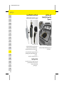
Porsche Mobile Charger
9Y0.000.003.B-ROW
001_BA_Umschlag_row.fm Page 1

US
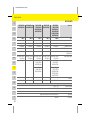
Porsche Mobile Charger
Operating Manual.................................1
FC
Porsche Mobile Charger
Manuel technique..............................20
ESM
Porsche Mobile Charger
Manual de instrucciones ..................42
PTB
Porsche Mobile Charger
Manual de operação ..........................62
TR
Porsche Mobile Charger
Kullanım Kılavuzu ............................. 83
RU
Porsche Mobile Charger
Руководство по эксплуатации.. 104
UK
Porsche Mobile Charger
Посібник з експлуатації .............. 125
MON
Porsche Mobile Charger
Ашиглалтын гарын авлага.......... 146
VIE
Porsche Mobile Charger
Hướng dẫn vận hành.............. 167
HE
Porsche Mobile Charger
.................................. 188
AR
Porsche Mobile Charger
.................................... 209
JPN
Porsche Mobile Charger
.................................... 229
KOR
Porsche Mobile Charger
.................................... 250
CHS
Porsche Mobile Charger
......................................... 271
CHT
Porsche Mobile Charger
......................................... 288
THA
Porsche Mobile Charger
.................................. 308
ʤʬʲʴʤʪʩʸʣʮ
ঀဥ୰ྶ
֡ፕ֩
ᐇհЙы
¼n¤º°µ¦Äoµ
9Y0.000.003.B-ROW.book Page 2

1
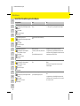
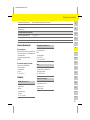
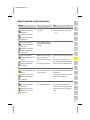
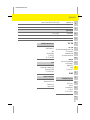
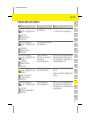
Table of Contents
English USA
Operating Instructions ...............................3
Important Safety Instructions........................................3
Intended Purpose...............................................................4
Key to Pictograms..............................................................4
Overview of Charger..........................................................5
Operating Instructions......................................................5
Vehicle Charge Ports and Vehicle Plugs......................6
Selecting a Supply Cable..................................................6
Changing Supply Cable.....................................................6
Control Unit..........................................................................8
Charging................................................................................8
Charging Current Limiting...............................................8
Charging Times...................................................................9
Moving and Storage Instructions...................................9
Transport..............................................................................9
Securing Transport Case
(example: Panamera 4 E-Hybrid) ..................................9
Basic Wall Mount ............................................................10
Vehicle Charge Port........................................................10
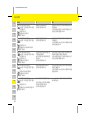
Control Unit Status Indicators
and Error Messages.......................................................... 11
Installation Instructions.......................... 15
Basic Wall Mount ............................................................15
Technical Data................................................................... 17
Production Information .................................................18
Index............................................................ 19
9Y0.000.003.B-ROW.book Page 1

2
US
FC
ESM
PTB
TR
RU
UK
MON
VIE
HE
AR
JPN
KOR
CHS
CHT
THA
Dr.Ing.h.c.F.PorscheAG is the owner of numerous
trademarks, both registered and unregistered,
including without limitation the Porsche Crest®,
Porsche®, Boxster®, Carrera®, Cayenne®, Cayman®,
Macan®, Panamera®, Spyder®, Tiptronic®, VarioCam®,
PCM®, PDK®, 911®, 718®, RS®, 4S®, 918 Spyder®,
FOUR, UNCOMPROMISED®, and the model numbers
and the distinctive shapes of the Porsche automo-
biles such as, the federally registered 911 and
Boxster automobiles. The third party trademarks
contained herein are the properties of their respec-
tive owners. All text, images, and other content in this
publication are protected by copyright. No part of this
publication may be reproduced in any form or by any
means without prior written permission of Porsche
Cars North America, Inc. Some vehicles may be
shown with non-U.S. equipment. Porsche recom-
mends seat belt usage and observance of traffic laws
at all times.
© 2019 Porsche Cars North America, Inc.
Operating manual
SAVE THESE INSTRUCTIONS: Always keep this
Operating Manual in the transport case for the
Porsche Mobile Charger and please hand it over to
the new owner if you sell your vehicle.
Suggestions
Do you have any questions, suggestions or ideas
regarding your vehicle or for the Operating Manual?
Please contact us:
1-800-PORSCHE
customer.relations@porsche.us
Equipment
Because Porsche vehicles undergo continuous
development, equipment and specifications may not
be as illustrated or described in this Operating
Manual. Items of equipment are sometimes optional
or vary depending on the country in which the vehicle
is sold. For information on retrofitting options, please
contact an authorized Porsche dealer. Porsche
recommends an authorized Porsche dealer, as they
have trained technicians and the necessary parts and
tools.
Owing to the different legal requirements in individual
countries, the equipment in your vehicle may vary
from that described in this Operating Manual.
If your Porsche is fitted with any equipment not
described in this manual, your authorized Porsche
dealer will be glad to provide information regarding
correct operation and care of the items concerned.
Owner's manual
You can find further information about your vehicle in
the Owner's Manual. Pay particular attention to the
warning and safety instructions.
Warnings and symbols
Different types of warnings and symbols are used in
this Operating Manual.
b Prerequisites that must be met in order to use a
function.
e Instructions that must be followed.
1. Instructions are numbered in cases where a
sequence of steps must be followed.
f Indicates where you can find more information on
a topic.
Item number Press date
9Y0.
000.003.B-ROW 05/2020
DANGER
Serious injury or death
Failure to observe warnings in the “Danger” category
will result in serious injury or death.
WARNING
Possible serious injury or
death
Failure to observe warnings in the “Warning”
category can result in serious injury or death.
CAUTION
Possible moderate or
minor injury
Failure to observe warnings in the “Caution” category
can result in moderate or minor injuries.
NOTICE
Failure to observe warnings in the “Notice” category
can result in damage to the vehicle.
Information
Additional information is indicated using the word
“Information”.
9Y0.000.003.B-ROW.book Page 2

3
Operating Instructions
US
FC
ESM
PTB
TR
RU
UK
MON
VIE
HE
AR
JPN
KOR
CHS
CHT
THA
Operating Instructions
Important Safety Instructions
NOTE: This equipment has been tested and found to
comply with the limits for a Class B digital device,
pursuant to Part 15 of the FCC Rules. These limits are
designed to provide reasonable protection against
harmful interference in a residential installation. This
equipment generates, uses and can radiate radio
frequency energy and, if not installed and used in
accordance with the instructions, may cause harmful
interference to radio communications. However,
there is no guarantee that interference will not occur
in a particular installation.
DANGER
Electric shock, short
circuit, fire, explosion
Use of a damaged or incorrect charging cable and of
a damaged or incorrect electrical socket, improper
use of the charger or failure to observe the safety
instructions can lead to short circuits, electric
shocks, explosions, fires or burns.
e Do not use a damaged and/or soiled charger.
Check the cable and plug connection for damage
and soiling before use.
e Only connect the charger to properly installed and
undamaged electrical sockets and fault-free
electrical installations.
e Do not use extension cables, cable reels, multiple
sockets or (travel) adapters.
e Disconnect the charger from the power grid
during thunder storms.
e Do not modify or repair any of the electrical
components.
e Never immerse the charger or the plugs in water.
e Only clean the charger when the control unit has
been fully disconnected from the power grid and
from the vehicle. Use a dry cloth for cleaning.
DANGER
Electric shock, fire
Incorrectly installed electrical sockets can cause
electric shock or fire when the high-voltage battery is
charged using the vehicle charge port.
e Installation and initial operation of the electrical
socket for the charger may only be carried out by
an electrically skilled person. The electrically
skilled person is fully responsible for compliance
with the relevant standards and regulations.
e The charger should only be operated in properly
earthed power supply systems. Operation in non-
earthed systems (e.g. IT networks) is not
possible.
e The cross-section of the cable for the electrical
socket is defined in accordance with the wire
length and the locally applicable regulations and
standards.
e To ensure uninterrupted charging, we recom-
mend that you only use electrical sockets that are
connected via a separately fused electric circuit
for charging.
e The charger is intended for use in private and
semi-public areas (e.g. private property, company
parking). Country dependent, Mode 2 charging is
prohibited in public areas and public spaces.
e Unauthorized persons (e.g. playing children) must
not have access to the charger or the vehicle
during unsupervised charging.
e Please read the safety instructions in the Installa-
tion Instructions and the Owner's Manual.
DANGER
Electric shock, fire
Incorrect handling of the plug contacts can lead to
electric shock or fire.
e Do not touch the contacts of the vehicle charge
port or the charger.
e Do not insert any objects into the vehicle charge
port or into the charger.
e Protect electrical sockets and plug connections
against moisture, water and other liquids.
WARNING
Flammable or explosive
vapors
Components of the charger can cause sparks and
ignite flammable or explosive vapors.
e To reduce the risk of explosion, particularly in
garages, make sure that the control unit is
located at least 19.7 in. (50 cm) above the floor
during charging.
e The charger must not be used in potentially
explosive atmospheres.
9Y0.000.003.B-ROW.book Page 3

4
Operating Instructions
US
FC
ESM
PTB
TR
RU
UK
MON
VIE
HE
AR
JPN
KOR
CHS
CHT
THA
If this equipment does cause harmful interference to
radio or television reception, which can be deter-
mined by turning the equipment off and on, the user
is encouraged to try to correct the interference by
one or more of the following measures:
– Reorient or relocate the receiving antenna.
– Increase the separation between the equipment
and receiver.
– Connect the equipment into an outlet on a circuit
different from that to which the receiver is
connected.
– Consult the dealer or an experienced radio/TV
technician for help.
Modifications not expressly approved by the
manufacturer could void the user’s authority to
operate the equipment under FCC rules.
To ensure uninterrupted charging, take the following
notes and recommendations into account:
– Before installing the charging infrastructure,
check that the necessary power for charging a
vehicle can be continuously provided with the
currently available domestic installation.
If necessary, protect the domestic installation
with a Home Energy Management System.
– When installing the electrical socket, select an
industrial electrical outlet with the highest
possible power available (adapted to the
domestic electric installation) and have it put into
operation by a qualified electrician.
– Where technically possible and legally permis-
sible, the electric installation must be dimen-
sioned in such a way that the maximum nominal
power of the electrical socket used is available for
charging the vehicle.
– In order to fully exploit the performance of the
charger and to ensure fast vehicle charging, use
either NEMA electrical sockets with the
maximum rated current or industrial electrical
outlets according to IEC 60309 for charging.
– When charging the high-voltage battery via the
household electrical outlet/industrial electrical
outlet, the electrical installation may be loaded to
its maximum capacity. It is recommended to have
electrical installations used for charging regularly
checked by an electrically skilled person. Ask a
qualified electrician which inspection intervals
are appropriate for your installation.
– On delivery, the charging current is automatically
limited to prevent overheating of the electrical
installation. Have a qualified electrician put the
charger into operation and set the charging
current limiting in accordance with to the
domestic installation.
f Refer to chapter “Charging Current Limiting”
on page 8.
Grounding instructions
Charger must be grounded.
If it should malfunction or break down, grounding
provides a path of least resistance for electric current
to reduce the risk of electric shock.
The charger is equipped with a cord having an equip-
ment grounding conductor and a grounding plug. The
plug must be plugged into an appropriate outlet that
is properly installed and grounded in accordance with
all local codes and ordinances.
Intended Purpose
Charger for operation in charging mode 2 for
charging vehicles with high-voltage batteries, which
meet the generally applicable standards and direc-
tives for electric vehicles.
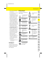
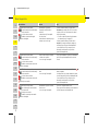
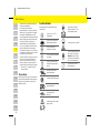
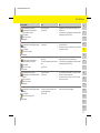
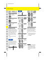
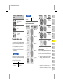
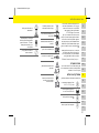
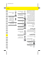
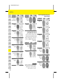
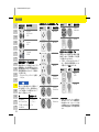
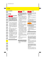
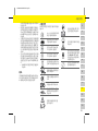
Key to Pictograms
Depending on the country, various pictograms may
be attached to the charger.
WARNING
Electric shock, short
circuit
Improper connection of the equipment-grounding
conductor is able to result in a risk of electric shock.
e Check with a qualified electrician or serviceman if
you are in doubt as to whether the product is
properly grounded.
e Do not modify the plug provided with the product
- if it will not fit the outlet, have a proper outlet
installed by a qualified electrician.
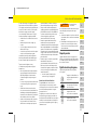
Operate the charger within a
temperature range from –22 °F to
+122 °F (–30 °C to +50 °C).
Operate the charger at an altitude
of max. 13,100 ft (4,000 m) above
sea level.
The charger is equipped with a
non-switched ground lead.
The charger is equipped with a
switched ground lead.
Dispose of the charger in compli-
ance with all applicable disposal
regulations.
9Y0.000.003.B-ROW.book Page 4

5
Operating Instructions
US
FC
ESM
PTB
TR
RU
UK
MON
VIE
HE
AR
JPN
KOR
CHS
CHT
THA
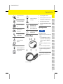
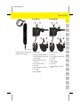
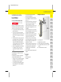
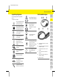
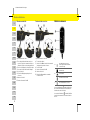
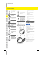
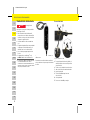
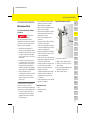
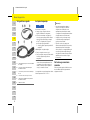
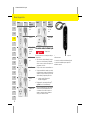
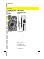
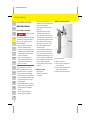
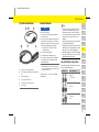
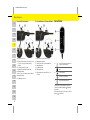
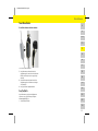
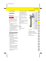
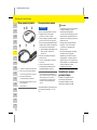
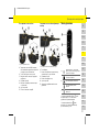
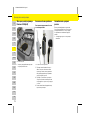
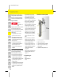
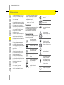
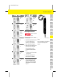
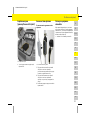
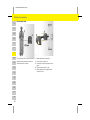
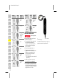
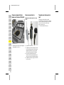
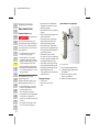
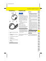
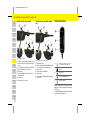
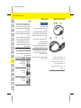
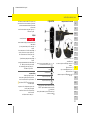
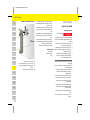
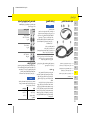
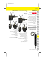
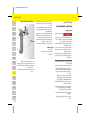
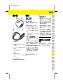
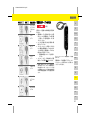
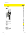
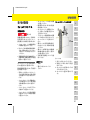
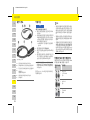
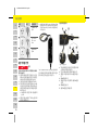
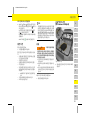
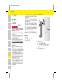
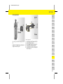
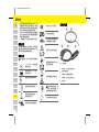
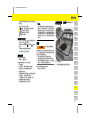
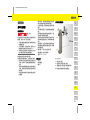
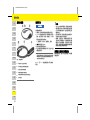
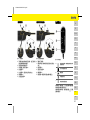
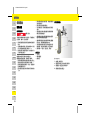
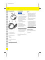
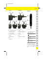
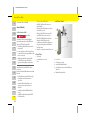
Overview of Charger
Fig. 1: Overview of charger
Operating Instructions
The charger can only be operated within a tempera-
ture range from –22 °F to +122 °F (–30 °C to
+50 °C).
Do not use extension cables or
cable reels.
Do not use any (travel) adapters.
Do not use multi-outlet power
strips.
Do not use charging cables with
damage to electronics or
connecting cables.
The charger requires a alternating
current power supply.
Risk of electric shock due to
improper use.
Observe the operating instructions
provided, particularly the warnings
and safety instructions.
The surface of the charger can
become very hot.
Do not operate the charger in non-
earthed power grids (e.g. IT
networks). Only operate the
charger in earthed power grids.
Operate the charger only in single-
phase supply systems.
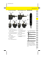
A Supply cable (pluggable to control unit)
B Plug of the supply cable connection at the control unit
C Power plug (plug for connecting to the power grid)
D Vehicle plug (connector plug for the vehicle)
E Vehicle cable (permanently installed on control unit)
F Control unit
NOTICE
Risk of damage to the charger.
e Always place the charger on a solid surface when
charging.
f It is recommended that the control unit be
placed in the basic wall mount during opera-
tion.Refer to chapter “Basic Wall Mount” on
page 10.
e Do not immerse or submerge the control unit in
water.
e Protect the control unit against snow and ice.
e Protect the charger against potential damage due
to being driven over, dropped, pulled, bent or
crushed.
9Y0.000.003.B-ROW.book Page 5

6
Operating Instructions
US
FC
ESM
PTB
TR
RU
UK
MON
VIE
HE
AR
JPN
KOR
CHS
CHT
THA
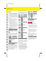
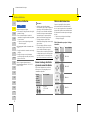
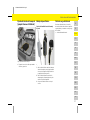
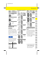
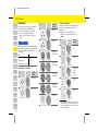
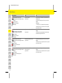
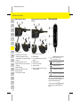
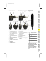
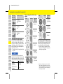
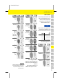
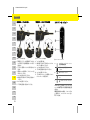
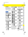
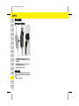
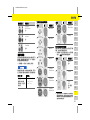
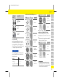
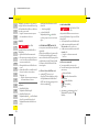
Vehicle Charge Ports and Vehicle
Plugs
Different vehicle charge ports A and vehicle plugs B
are available depending on the vehicle equipment.
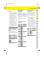
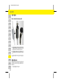
Selecting a Supply Cable
For regular charging with optimum charge speed, use
only the supply cables listed below. The maximum
achievable charging performance is up to 9.6 kW
(depending on the power supply/domestic connec-
tion and the on-board charger).
f Refer to chapter “Technical Data” on page 17.
Supply cables for industrial electrical outlets
Supply cables for household electrical outlets
If there is no industrial electrical outlet available, the
supply cables listed below can be used for charging
at a reduced charge speed.
e In Canada, each receptacle for the purpose of
electric vehicle charging shall be labelled in a
conspicuous, legible, and permanent manner,
identifying it as an electric vehicle supply equip-
ment receptacle and shall be a single receptacle
of CSA configuration 5-20R supplied from a 125
V branch circuit rated not less than 20 A.
Changing Supply Cable
Information
– In order to prevent overheating during operation,
do not expose the charger to direct sunlight for
lengthy periods. In the event of overheating of the
control unit, charging is interrupted automatically
until the temperature has returned to the normal
range.
– When driving abroad, always carry the appro-
priate supply cable for the charger with you for
use in the country you are visiting.
– Depending on the country, different safety
concepts with various device versions are stipu-
lated. Before traveling abroad, ensure that opera-
tion of the charger is permissible in the relevant
country. Further information is available from
your authorized Porsche dealer or your local
electricity supplier.
Vehicle charge
port and plug
Standard and designation
IEC 62196-2/
SAE-J1772-2009
Type 1
Electrical
socket
Plug Standard and designa-
tion
NEMA 14-30
NEMA 14-50
NEMA 6-30
NEMA 6-50
Electrical
socket
Plug Standard and designa-
tion
NEMA 5-15
Type B
DANGER
Electric shock
Risk of serious or fatal injury from electric shock.
e Before changing the supply cable, always unplug
the supply cable from the electrical socket and
remove the vehicle cable from the vehicle charge
port.
e Only change cables in a dry environment.
e The charger may only be used as a unit consisting
of supply cable and control unit with vehicle
cable.
e Only use cables approved by Porsche.
e In some countries, e.g. in Norway
1)
, changing the
supply cable is prohibited.
1) Time of printing. Further information is available from an
authorized Porsche dealer. Porsche recommends an
authorized Porsche dealer, as they have trained techni-
cians and the necessary parts and tools.
9Y0.000.003.B-ROW.book Page 6

7
Operating Instructions
US
FC
ESM
PTB
TR
RU
UK
MON
VIE
HE
AR
JPN
KOR
CHS
CHT
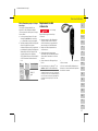
THA
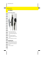
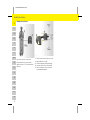
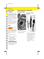
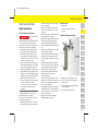
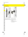
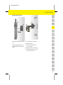
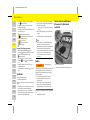
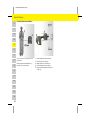
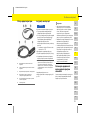
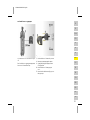
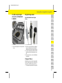
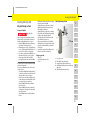
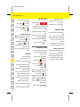
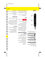
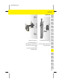
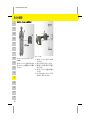
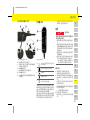
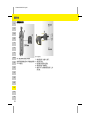
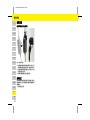
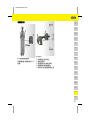
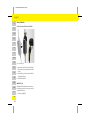
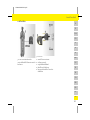
Fig. 2: Plug of the supply cable connection at the control unit
The plug of the supply cable connection is removed
and inserted at the top of the control unit.
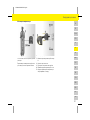
Disconnecting cable
Fig. 3: Disconnecting cables
b Charging of the high voltage battery has ended
and the vehicle plug has been disconnected from
the vehicle charge port.
b The plug has been disconnected from the
electrical socket.
1. Remove screw C with a suitable tool.
2. Lift the lever A.
3. Pull out the plug B until resistance is first felt.
4. Close the lever A.
5. Pull out the plug B fully.
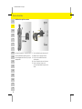
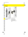
Securing cable and plug
Fig. 4: Securing cables and plugs
b Lever A is closed.
1. Insert the plug B into the control unit until resis-
tance is first felt.
2. Lift the lever A.
3. Push in the plug B fully.
4. Close the lever A.
5. Fasten the plug B at the control unit using
screw C.
9Y0.000.003.B-ROW.book Page 7

8
Operating Instructions
US
FC
ESM
PTB
TR
RU
UK
MON
VIE
HE
AR
JPN
KOR
CHS
CHT
THA
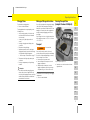
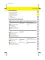
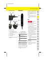
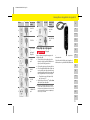
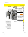
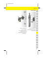
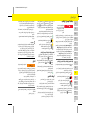
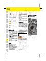
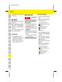
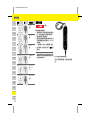
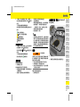
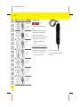
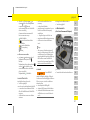
Control Unit
Fig. 5: Control unit
The operating state of the control unit and charging
current limiting can be set using the ON/OFF button
.
The control unit can be reset using the reset button
if residual current is detected.
The light indicators A – C indicate the operating state
of the control unit, whether charging current limiting
is set and possible faults by means of different colors,
illumination and flashing.
f Refer to chapter “Control Unit Status Indicators
and Error Messages” on page 11.
Charging
Starting charging
1. Insert the plug into the electrical socket.
The light indicators briefly light up red.
2. Insert the vehicle plug in the vehicle charge port.
The light indicator on the ON/OFF button
lights up yellow.
Following a successful self-test, all the light
indicators light up green for 2 seconds.
For information on connecting the vehicle cable
to the vehicle charge port:
f refer to the Owner’s Manual.
3. Charging starts automatically.
The light indicator on the ON/OFF button
pulsates green.
Charging is controlled by the vehicle. The charge
status is displayed in the vehicle.
Charging Current Limiting
The control unit detects the voltage and the available
current automatically.
Using charging current limiting, it is possible to set
whether full or half the charging power is used for
charging (100 % or 50 %). The last charging current
set is saved.
On delivery, the charging current is automatically
limited to 50 % to prevent overheating of the
electrical installation.
Setting charging current limiting
e Press the ON/OFF button for at least
2seconds.
After the charging current limiting has been set
successfully, the light indicators B flash green
once.
The set value (50 % or 100 %) is indicated to the
left or right of the ON/OFF button .
A
ON/OFF button with light indicator and
additional charging current limiting function
B
Power supply/domestic connection light
indicator
Vehicle light indicator
Control unit light indicator
C Reset button with light indicator
DANGER
Electric shock, fire
Risk of serious or fatal injury due to fire or electric
shock.
e Always observe the specified sequence when
charging the high-voltage battery.
e Do not disconnect the vehicle cable from the
electrical socket during the charging process. End
the charging process before disconnecting the
vehicle cable from the electrical socket.
e Do not disconnect the control unit from the
power grid during the charging process.
e Possible faults are indicated by means of
different colors, illumination and flashing of light
indicators A – C.
f Refer to chapter “Control Unit Status Indica-
tors and Error Messages” on page 11.
9Y0.000.003.B-ROW.book Page 8

9
Operating Instructions
US
FC
ESM
PTB
TR
RU
UK
MON
VIE
HE
AR
JPN
KOR
CHS
CHT
THA
Charging Times
For information on charging times:
f Refer to the Owner’s Manual.
The charging duration can vary depending on the
following factors:
– Current-carrying capacity of electrical socket
used (household electrical outlet or industrial
electrical outlet).
– Country-specific grid voltage and electric
current.
– Settings for charging current limiting on the
control unit.
– Fluctuations in the grid voltage.
– Ambient temperature of vehicle and charger.
Charging times may be longer in the limit ranges
of the permissible ambient temperature.
f Refer to chapter “Technical Data” on page 17.
– Temperature of the high-voltage battery and
control unit.
– Passenger compartment precooling/heating
activated.
Moving and Storage Instructions
Do not lift, carry and move the charger by the Supply
cable, Vehicle cable, Power plug or Vehicle plug.
Always lift, carry and move the whole device. Do not
damage the Control unit, the cables or plugs when
moving, for example by dragging over the floor or
sharp edges.
Proper storage: Store in a cool dry place away from
direct sunlight: not below –22 °F (–30 °C) or above
+122 °F (+50 °C).
Transport
For information on the tie-down rings in the luggage
compartment:
f refer to the Owner’s Manual.
Securing Transport Case
(example: Panamera 4 E-Hybrid)
Fig. 6: Securing the transport case
e Attach the case to the front and rear tie-down
rings with hooks.
Information
– Due to different national power grid systems,
various cable versions are supplied. This may
result in the full charging performance not being
available. Further information is available from
your authorized Porsche dealer.
WARNING
Unsecured load
Unsecured, incorrectly secured or incorrectly
positioned charger can slip out of place and endanger
the vehicle occupants during braking, acceleration,
direction changes or in accidents.
e Never transport charger unsecured.
e Stow the charger in the transport case in the
luggage compartment.
e Always transport the transport case in the
luggage compartment, never in the passenger
compartment (e.g. on or in front of the seats).
9Y0.000.003.B-ROW.book Page 9

10
Operating Instructions
US
FC
ESM
PTB
TR
RU
UK
MON
VIE
HE
AR
JPN
KOR
CHS
CHT
THA
Basic Wall Mount
Attaching control unit to wall mount
Fig. 7: Attaching the control unit
1. Guide the vehicle cable through the lower
opening of the wall mount, fit the control unit
onto the lower locking tabs and engage towards
the rear.
2. Guide the supply cable through the upper
opening of the wall mount and lock the snap ring
on the left.
3. Insert the vehicle plug in the connector fastener.
Vehicle Charge Port
For information on connecting and disconnecting the
vehicle cable to and from the vehicle charge port and
for the charging and connection status at the vehicle
charge port:
f refer to the Owner’s Manual.
9Y0.000.003.B-ROW.book Page 10

11
Operating Instructions
US
FC
ESM
PTB
TR
RU
UK
MON
VIE
HE
AR
JPN
KOR
CHS
CHT
THA
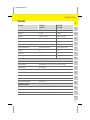
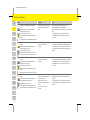
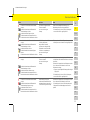
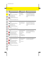
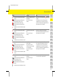
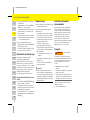
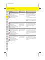
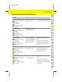
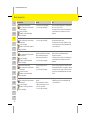
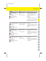
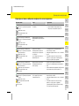
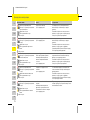
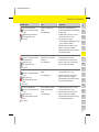
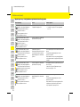
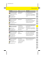
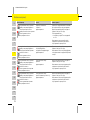
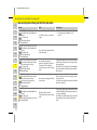
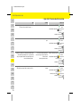
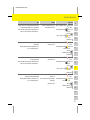
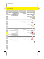
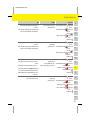
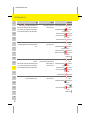
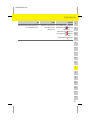
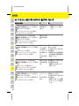
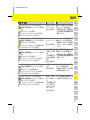
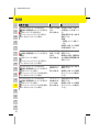
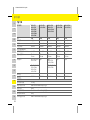
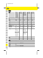
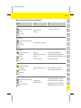
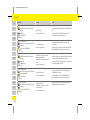
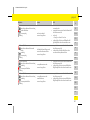
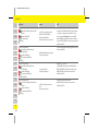
Control Unit Status Indicators and Error Messages
Light indicators Meaning Remedy
ON/OFF lights up green.
Power supply/domestic connection is off.
Vehicle is off.
Control unit is off.
Reset is off.
The charger is ready for charging, but no
charging takes place.
e Start the charging process.
f Refer to chapter “Starting charging” on page 8.
ON/OFF pulses green.
Power supply/domestic connection is off.
Vehicle is off.
Control unit is off.
Reset is off.
The vehicle is charged with protective
conductor monitoring activated.
ON/OFF pulses green.
Power supply/domestic connection is off.
Vehicle is off.
Control unit is off.
Reset is off.
The power plug is overheated.
Possible fault cause: multiphase socket
connected only as single phase.
Charging is performed at a reduced rate.
The fault is automatically reset once the power plug has
cooled down.
Until it has cooled down, charging resumes at a lower rate.
e If the fault persists, have the power supply/domestic
connection checked by a qualified electrician.
ON/OFF pulses green.
Power supply/domestic connection is off.
Vehicle is off.
Control unit lights up yellow.
Reset is off.
The control unit is overheated.
Charging is performed at a reduced rate.
The fault is automatically reset once the control unit has
cooled down.
Until it has cooled down, charging resumes at a lower rate.
e If the fault persists, have the control unit checked by a
specialist dealer/authorized Porsche dealer.
ON/OFF lights up red.
Power supply/domestic connection is off.
Vehicle is off.
Control unit is off.
Reset is off.
The power plug is overheated.
The charging process is interrupted.
The fault is automatically reset and charging resumed once
the power plug has cooled down.
e If the fault persists, have the power supply/domestic
connection checked by a qualified electrician.
ON/OFF lights up red.
Power supply/domestic connection is off.
Vehicle is off.
Control unit lights up yellow.
Reset is off.
The control unit is overheated.
The charging process is interrupted.
The fault is automatically reset and charging resumed once
the control unit has cooled down.
e If the fault persists, have the control unit checked by a
specialist dealer/authorized Porsche dealer.
9Y0.000.003.B-ROW.book Page 11

12
Operating Instructions
US
FC
ESM
PTB
TR
RU
UK
MON
VIE
HE
AR
JPN
KOR
CHS
CHT
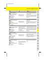
THA
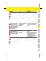
ON/OFF lights up red.
Power supply/domestic connection flashes yellow.
Vehicle is off.
Control unit is off.
Reset is off.
The charging infrastructure of power
supply/domestic connection is limited.
Possible fault cause: Undervoltage or
poor grid frequency.
The charging process is interrupted.
The fault is automatically reset once the power supply/
domestic connection has stabilized.
e If the fault persists, have the power supply/domestic
connection checked by a qualified electrician.
ON/OFF lights up red.
Power supply/domestic connection is off.
Vehicle flashes yellow.
Control unit is off.
Reset is off.
The vehicle charging system is faulty.
The charging process is interrupted.
The fault is automatically reset once the vehicle charging
system has stabilized.
e If the fault persists, have the vehicle checked by a
specialist dealer/authorized Porsche dealer.
ON/OFF lights up red.
Power supply/domestic connection is off.
Vehicle is off.
Control unit flashes yellow.
Reset is off.
The supply or vehicle cable is defective.
Possible fault cause: The coding resis-
tances of the grid supply and vehicle
cable do not match.
The charging process is interrupted.
e Have the grid supply or vehicle cable replaced by a
specialist dealer/authorized Porsche dealer.
ON/OFF lights up red.
Power supply/domestic connection is off.
Vehicle lights up red.
Control unit is off.
Reset is off.
The vehicle charging system is faulty.
The charging process is interrupted.
e End the charging process at the vehicle and disconnect
the vehicle cable from the vehicle charge port.
e Disconnect the charger from the power grid and connect it
to the power grid again after 60 seconds.
e Re-start charging.
f Refer to chapter “Starting charging” on page 8.
e If the fault persists, have the vehicle checked by a
specialist dealer/authorized Porsche dealer.
ON/OFF lights up red.
Power supply/domestic connection flashes red.
Vehicle is off.
Control unit is off.
Reset is off.
There is overvoltage in the charging
infrastructure of the power supply/
domestic connection. The charging
process is interrupted.
e Disconnect the charger from the power grid and connect it
to the power grid again after 60 seconds.
e If the fault persists, have the power supply/domestic
connection checked by a qualified electrician.
ON/OFF lights up red.
Power supply/domestic connection is off.
Vehicle is off.
Control unit lights up red.
Reset is off.
The control unit has a technical fault.
The charging process is interrupted.
e Disconnect the charger from the power grid and connect it
to the power grid again after 60 seconds.
e If the fault persists, have the control unit checked by a
specialist dealer/authorized Porsche dealer.
Light indicators Meaning Remedy
9Y0.000.003.B-ROW.book Page 12

13
Operating Instructions
US
FC
ESM
PTB
TR
RU
UK
MON
VIE
HE
AR
JPN
KOR
CHS
CHT
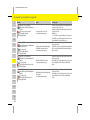
THA
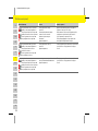
ON/OFF lights up red.
Power supply/domestic connection is off.
Vehicle is off.
Control unit flashes red.
Reset is off.
The control unit has a technical fault
(self-test failed). The charging process
is interrupted.
e Disconnect the charger from the power grid and connect it
to the power grid again after 60 seconds.
e If the fault persists, have the control unit checked by a
specialist dealer/authorized Porsche dealer.
ON/OFF lights up red.
Power supply/domestic connection lights up red.
Vehicle lights up red.
Control unit is off.
Reset is off.
The charging infrastructure of power
supply/domestic connection is insuffi-
cient: The protective conductor is inter-
rupted or not present.
Protective conductor monitoring has
interrupted the charging process.
e Have the control unit checked by a specialist dealer/
authorized Porsche dealer and the power supply/domestic
connection checked by a qualified electrician.
ON/OFF lights up red.
Power supply/domestic connection lights up red.
Vehicle lights up red.
Control unit lights up red.
Reset is off.
The light indicator in the Reset button
on the control unit is defective.
The charging process is interrupted.
e Have the control unit replaced by a specialist dealer/
authorized Porsche dealer.
ON/OFF lights up red.
Power supply/domestic connection lights up red.
Vehicle lights up red.
Control unit lights up red.
Reset flashes red.
The control unit has detected residual
current.
The charging process is interrupted.
e Press and hold the Reset button for 2 seconds.
e If the fault persists, have the control unit checked by a
specialist dealer/authorized Porsche dealer and the power
supply/domestic connection checked by a qualified
electrician.
ON/OFF lights up red.
Power supply/domestic connection flashes red.
Vehicle flashes red.
Control unit flashes red.
Reset is off.
The charging infrastructure is incor-
rectly wired.
The charging process is interrupted.
e Disconnect the charger from the power grid.
e Have the power supply/domestic connection checked by
a qualified electrician.
Light indicators Meaning Remedy
9Y0.000.003.B-ROW.book Page 13

14
Operating Instructions
US
FC
ESM
PTB
TR
RU
UK
MON
VIE
HE
AR
JPN
KOR
CHS
CHT
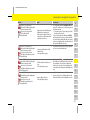
THA
ON/OFF lights up red.
Power supply/domestic connection lights up red.
Vehicle lights up red.
Control unit lights up red.
Reset lights up red.
The control unit has a technical fault.
Possible fault cause: Software error or
load relay incorrectly connected.
The charging process is interrupted.
e Disconnect the charger from the power grid and connect it
to the power grid again after 60 seconds.
e If the fault persists, have the control unit checked by a
specialist dealer/authorized Porsche dealer and the power
supply/domestic connection checked by a qualified
electrician.
ON/OFF flashes red.
Power supply/domestic connection is off.
Vehicle is off.
Control unit lights up red.
Reset is off.
The control unit has a serious fault.
The charging process is interrupted.
e Have the control unit replaced by a specialist dealer/
authorized Porsche dealer.
ON/OFF is off.
Power supply/domestic connection lights up red.
Vehicle lights up red.
Control unit lights up red.
Reset lights up red.
The light indicator in the ON/OFF
button on the control unit is defective.
The charging process is interrupted.
e Have the control unit replaced by a specialist dealer/
authorized Porsche dealer.
Light indicators Meaning Remedy
9Y0.000.003.B-ROW.book Page 14

15
Installation Instructions
US
FC
ESM
PTB
TR
RU
UK
MON
VIE
HE
AR
JPN
KOR
CHS
CHT
THA
Installation Instructions
Basic Wall Mount
Selecting a suitable installation location
The basic wall mount is designed for indoor and
outdoor installations.
The following criteria should be considered when
selecting a suitable installation location:
– Install the electrical socket and basic wall mount
preferably in a covered area protected against
direct sunlight and rain (e.g. in a garage).
– Do not spray the basic wall mount directly with
water (e.g. high-pressure cleaning equipment or
garden hoses).
– Do not install the basic wall mount under
suspended or hanging objects.
– Do not install the basic wall mount in stables,
livestock buildings or locations where ammonia
gases occur.
– Install the basic wall mount on a smooth surface.
– In order to ensure secure fastening, check the
condition of the wall before installing.
– Install the basic wall mount so that it is not near
pathways and the charging cables do not cross
any pathways.
– Install the basic wall mount so that the distance
between the plug and the socket does not exceed
the length of the available supply cable.
– Install the electrical socket as close as possible
the preferred vehicle parking position. Take the
orientation of the vehicle into account.
– The distance of the electrical socket from the
floor and ceiling should be selected in compliance
with national regulations and standards so that
comfortable use is ensured:
The Mobile Charger shall be mounted at a suffi-
cient height from grade such that the height of
the storage means for the coupling device is
located between 24 in. (600 mm) and 4 ft.
(1.2 m) from grade.
f Refer to chapter “Important Safety Instructions”
on page 3.
Tools required
–Spirit level
– power or hammer drill
–screwdriver
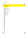
Installing basic wall mount
Fig. 1: Drilling dimensions
1. Mark the drill holes on the wall.
2. Drill the mounting holes and insert wall plugs.
3. Press wall mount 2 from the front into the cable
guide 1.
4. Screw the wall mount onto the wall.
DANGER
Electric shock, fire
Improper use of the Mobile Charger or non-compli-
ance with the safety instructions may result in short
circuits, electric shocks, explosions, fires or burns.
e Do not install the basic wall mount in potentially
explosive atmospheres.
e To reduce the risk of explosion, particularly in
garages, make sure that the control unit is located
at least 19.7 in. (50 cm) above the floor during
charging.
e To reduce the risk of fire, connect only to a circuit
provided with 20 amperes (for Mobile Charger
with 3.6 kW/16 A) or 50 amperes (for Mobile
Charger with 9.6 kW/40 A) maximum branch
circuit overcurrent protection in accordance with
the ANSI/NFPA 70 National Electrical code.
e Observe the locally applicable electrical installa-
tion regulations, fire protection measures,
accident prevention regulations and escape
routes.
9Y0.000.003.B-ROW.book Page 15

16
Installation Instructions
US
FC
ESM
PTB
TR
RU
UK
MON
VIE
HE
AR
JPN
KOR
CHS
CHT
THA
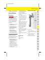
Installing connector fastener
Fig. 2: Distance wall mount – connector fastener
During installation of the connector fastener,
maintain a clearance of 7.9 in. (200 mm) from the
wall mount.
Fig. 3: Drilling dimensions
1. Take the connector fastener 1 out of the cover 2.
2. Mark the drill holes on the wall.
3. Drill the mounting holes and insert wall plugs.
4. Screw the connector fastener 1 onto the wall.
5. Fit the cover 2 onto the connector fastener 1
from below and push upwards.
9Y0.000.003.B-ROW.book Page 16

17
Installation Instructions
US
FC
ESM
PTB
TR
RU
UK
MON
VIE
HE
AR
JPN
KOR
CHS
CHT
THA
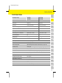
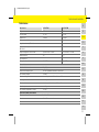
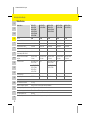
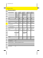
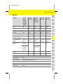
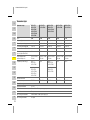
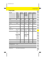
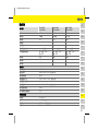
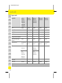
Technical Data
Electrical data 7PP.971.675.AA
9Y0.971.675.BA
7PP.971.675.AB
9Y0.971.675.BB
Power 3.6 kW 9.6 kW
Rated current 16 A 1-phase 40 A 1-phase
Grid voltage 120-240 V, 120 V to GND 120-240 V, 120 V to GND
Power grid frequency 50 Hz/60 Hz 50 Hz/60 Hz
Overvoltage category (EN 60664) II II
Rated short-time withstand current (EN 61439-1) <10 kA eff. <10 kA eff.
Integrated residual current device Type A (AC: 20 mA) + DC: 56 mA Type A (AC: 20 mA) + DC: 56 mA
Vehicle plug Type 1 Type 1
Protection class I I
Type of protection NEMA 3 (IP55) NEMA 3 (IP55)
Mechanical data
Weight of control unit 5.3 lbs (2.4 kg) - 7.7 lbs (3.5 kg)
Wall mount dimensions Width x height x depth: 5.3 in. x 15.4 in. x 3.0 in. (136 mm x 391 mm x 76 mm)
Weight of wall mount approx. 1.0 lb (450 g)
Cable guide dimensions Width x height x depth: 5.0 in. x 5.5 in. x 4.5 in. (127 mm x 139 mm x 115 mm)
Weight of cable guide approx. 0.9 lb (420 g)
Connector fastener dimensions Width x height x depth: 5.4 in. x 6.8 in. x 2.0 in. (136 mm x 173 mm x 50 mm)
Weight of connector fastener approx. 0.3 lb (140 g)
Weight of complete basic wall mount approx. 2.2 lbs (1 kg)
Ambient and storage conditions
Ambient temperature –22 °F to +122 °F (–30 °C to +50 °C)
Humidity 5 % – 95 % non-condensing
Elevation max. 13,100 ft (4,000 m) above sea level
9Y0.000.003.B-ROW.book Page 17

18
Installation Instructions
US
FC
ESM
PTB
TR
RU
UK
MON
VIE
HE
AR
JPN
KOR
CHS
CHT
THA
Production Information
Date of manufacture
The date of manufacture of the charger can be found
on the identification plate after the abbreviation
"EOL".
It is specified in the following format:
Day of production.Month of production.Year of
production
Charger manufacturer
Aptiv Services Deutschland GmbH
Am Technologiepark 1
42119 Wuppertal
Germany
Tel.: +49 202 291 0
9Y0.000.003.B-ROW.book Page 18
Sayfa yükleniyor...
Sayfa yükleniyor...
Sayfa yükleniyor...
Sayfa yükleniyor...
Sayfa yükleniyor...
Sayfa yükleniyor...
Sayfa yükleniyor...
Sayfa yükleniyor...
Sayfa yükleniyor...
Sayfa yükleniyor...
Sayfa yükleniyor...
Sayfa yükleniyor...
Sayfa yükleniyor...
Sayfa yükleniyor...
Sayfa yükleniyor...
Sayfa yükleniyor...
Sayfa yükleniyor...
Sayfa yükleniyor...
Sayfa yükleniyor...
Sayfa yükleniyor...
Sayfa yükleniyor...
Sayfa yükleniyor...
Sayfa yükleniyor...
Sayfa yükleniyor...
Sayfa yükleniyor...
Sayfa yükleniyor...
Sayfa yükleniyor...
Sayfa yükleniyor...
Sayfa yükleniyor...
Sayfa yükleniyor...
Sayfa yükleniyor...
Sayfa yükleniyor...
Sayfa yükleniyor...
Sayfa yükleniyor...
Sayfa yükleniyor...
Sayfa yükleniyor...
Sayfa yükleniyor...
Sayfa yükleniyor...
Sayfa yükleniyor...
Sayfa yükleniyor...
Sayfa yükleniyor...
Sayfa yükleniyor...
Sayfa yükleniyor...
Sayfa yükleniyor...
Sayfa yükleniyor...
Sayfa yükleniyor...
Sayfa yükleniyor...
Sayfa yükleniyor...
Sayfa yükleniyor...
Sayfa yükleniyor...
Sayfa yükleniyor...
Sayfa yükleniyor...
Sayfa yükleniyor...
Sayfa yükleniyor...
Sayfa yükleniyor...
Sayfa yükleniyor...
Sayfa yükleniyor...
Sayfa yükleniyor...
Sayfa yükleniyor...
Sayfa yükleniyor...
Sayfa yükleniyor...
Sayfa yükleniyor...
Sayfa yükleniyor...
Sayfa yükleniyor...
Sayfa yükleniyor...
Sayfa yükleniyor...
Sayfa yükleniyor...
Sayfa yükleniyor...
Sayfa yükleniyor...
Sayfa yükleniyor...
Sayfa yükleniyor...
Sayfa yükleniyor...
Sayfa yükleniyor...
Sayfa yükleniyor...
Sayfa yükleniyor...
Sayfa yükleniyor...
Sayfa yükleniyor...
Sayfa yükleniyor...
Sayfa yükleniyor...
Sayfa yükleniyor...
Sayfa yükleniyor...
Sayfa yükleniyor...
Sayfa yükleniyor...
Sayfa yükleniyor...
Sayfa yükleniyor...
Sayfa yükleniyor...
Sayfa yükleniyor...
Sayfa yükleniyor...
Sayfa yükleniyor...
Sayfa yükleniyor...
Sayfa yükleniyor...
Sayfa yükleniyor...
Sayfa yükleniyor...
Sayfa yükleniyor...
Sayfa yükleniyor...
Sayfa yükleniyor...
Sayfa yükleniyor...
Sayfa yükleniyor...
Sayfa yükleniyor...
Sayfa yükleniyor...
Sayfa yükleniyor...
Sayfa yükleniyor...
Sayfa yükleniyor...
Sayfa yükleniyor...
Sayfa yükleniyor...
Sayfa yükleniyor...
Sayfa yükleniyor...
Sayfa yükleniyor...
Sayfa yükleniyor...
Sayfa yükleniyor...
Sayfa yükleniyor...
Sayfa yükleniyor...
Sayfa yükleniyor...
Sayfa yükleniyor...
Sayfa yükleniyor...
Sayfa yükleniyor...
Sayfa yükleniyor...
Sayfa yükleniyor...
Sayfa yükleniyor...
Sayfa yükleniyor...
Sayfa yükleniyor...
Sayfa yükleniyor...
Sayfa yükleniyor...
Sayfa yükleniyor...
Sayfa yükleniyor...
Sayfa yükleniyor...
Sayfa yükleniyor...
Sayfa yükleniyor...
Sayfa yükleniyor...
Sayfa yükleniyor...
Sayfa yükleniyor...
Sayfa yükleniyor...
Sayfa yükleniyor...
Sayfa yükleniyor...
Sayfa yükleniyor...
Sayfa yükleniyor...
Sayfa yükleniyor...
Sayfa yükleniyor...
Sayfa yükleniyor...
Sayfa yükleniyor...
Sayfa yükleniyor...
Sayfa yükleniyor...
Sayfa yükleniyor...
Sayfa yükleniyor...
Sayfa yükleniyor...
Sayfa yükleniyor...
Sayfa yükleniyor...
Sayfa yükleniyor...
Sayfa yükleniyor...
Sayfa yükleniyor...
Sayfa yükleniyor...
Sayfa yükleniyor...
Sayfa yükleniyor...
Sayfa yükleniyor...
Sayfa yükleniyor...
Sayfa yükleniyor...
Sayfa yükleniyor...
Sayfa yükleniyor...
Sayfa yükleniyor...
Sayfa yükleniyor...
Sayfa yükleniyor...
Sayfa yükleniyor...
Sayfa yükleniyor...
Sayfa yükleniyor...
Sayfa yükleniyor...
Sayfa yükleniyor...
Sayfa yükleniyor...
Sayfa yükleniyor...
Sayfa yükleniyor...
Sayfa yükleniyor...
Sayfa yükleniyor...
Sayfa yükleniyor...
Sayfa yükleniyor...
Sayfa yükleniyor...
Sayfa yükleniyor...
Sayfa yükleniyor...
Sayfa yükleniyor...
Sayfa yükleniyor...
Sayfa yükleniyor...
Sayfa yükleniyor...
Sayfa yükleniyor...
Sayfa yükleniyor...
Sayfa yükleniyor...
Sayfa yükleniyor...
Sayfa yükleniyor...
Sayfa yükleniyor...
Sayfa yükleniyor...
Sayfa yükleniyor...
Sayfa yükleniyor...
Sayfa yükleniyor...
Sayfa yükleniyor...
Sayfa yükleniyor...
Sayfa yükleniyor...
Sayfa yükleniyor...
Sayfa yükleniyor...
Sayfa yükleniyor...
Sayfa yükleniyor...
Sayfa yükleniyor...
Sayfa yükleniyor...
Sayfa yükleniyor...
Sayfa yükleniyor...
Sayfa yükleniyor...
Sayfa yükleniyor...
Sayfa yükleniyor...
Sayfa yükleniyor...
Sayfa yükleniyor...
Sayfa yükleniyor...
Sayfa yükleniyor...
Sayfa yükleniyor...
Sayfa yükleniyor...
Sayfa yükleniyor...
Sayfa yükleniyor...
Sayfa yükleniyor...
Sayfa yükleniyor...
Sayfa yükleniyor...
Sayfa yükleniyor...
Sayfa yükleniyor...
Sayfa yükleniyor...
Sayfa yükleniyor...
Sayfa yükleniyor...
Sayfa yükleniyor...
Sayfa yükleniyor...
Sayfa yükleniyor...
Sayfa yükleniyor...
Sayfa yükleniyor...
Sayfa yükleniyor...
Sayfa yükleniyor...
Sayfa yükleniyor...
Sayfa yükleniyor...
Sayfa yükleniyor...
Sayfa yükleniyor...
Sayfa yükleniyor...
Sayfa yükleniyor...
Sayfa yükleniyor...
Sayfa yükleniyor...
Sayfa yükleniyor...
Sayfa yükleniyor...
Sayfa yükleniyor...
Sayfa yükleniyor...
Sayfa yükleniyor...
Sayfa yükleniyor...
Sayfa yükleniyor...
Sayfa yükleniyor...
Sayfa yükleniyor...
Sayfa yükleniyor...
Sayfa yükleniyor...
Sayfa yükleniyor...
Sayfa yükleniyor...
Sayfa yükleniyor...
Sayfa yükleniyor...
Sayfa yükleniyor...
Sayfa yükleniyor...
Sayfa yükleniyor...
Sayfa yükleniyor...
Sayfa yükleniyor...
Sayfa yükleniyor...
Sayfa yükleniyor...
Sayfa yükleniyor...
Sayfa yükleniyor...
Sayfa yükleniyor...
Sayfa yükleniyor...
Sayfa yükleniyor...
Sayfa yükleniyor...
Sayfa yükleniyor...
Sayfa yükleniyor...
Sayfa yükleniyor...
Sayfa yükleniyor...
Sayfa yükleniyor...
Sayfa yükleniyor...
Sayfa yükleniyor...
Sayfa yükleniyor...
Sayfa yükleniyor...
Sayfa yükleniyor...
Sayfa yükleniyor...
Sayfa yükleniyor...
Sayfa yükleniyor...
Sayfa yükleniyor...
Sayfa yükleniyor...
Sayfa yükleniyor...
Sayfa yükleniyor...
Sayfa yükleniyor...
Sayfa yükleniyor...
Sayfa yükleniyor...
Sayfa yükleniyor...
Sayfa yükleniyor...
Sayfa yükleniyor...
Sayfa yükleniyor...
Sayfa yükleniyor...
Sayfa yükleniyor...
Sayfa yükleniyor...
Sayfa yükleniyor...
Sayfa yükleniyor...
Sayfa yükleniyor...
Sayfa yükleniyor...
Sayfa yükleniyor...
Sayfa yükleniyor...
Sayfa yükleniyor...
Sayfa yükleniyor...
Sayfa yükleniyor...
Sayfa yükleniyor...
Sayfa yükleniyor...
Sayfa yükleniyor...
Sayfa yükleniyor...
Sayfa yükleniyor...
Sayfa yükleniyor...
Sayfa yükleniyor...
Sayfa yükleniyor...
Sayfa yükleniyor...
Sayfa yükleniyor...
Sayfa yükleniyor...
-
 1
1
-
 2
2
-
 3
3
-
 4
4
-
 5
5
-
 6
6
-
 7
7
-
 8
8
-
 9
9
-
 10
10
-
 11
11
-
 12
12
-
 13
13
-
 14
14
-
 15
15
-
 16
16
-
 17
17
-
 18
18
-
 19
19
-
 20
20
-
 21
21
-
 22
22
-
 23
23
-
 24
24
-
 25
25
-
 26
26
-
 27
27
-
 28
28
-
 29
29
-
 30
30
-
 31
31
-
 32
32
-
 33
33
-
 34
34
-
 35
35
-
 36
36
-
 37
37
-
 38
38
-
 39
39
-
 40
40
-
 41
41
-
 42
42
-
 43
43
-
 44
44
-
 45
45
-
 46
46
-
 47
47
-
 48
48
-
 49
49
-
 50
50
-
 51
51
-
 52
52
-
 53
53
-
 54
54
-
 55
55
-
 56
56
-
 57
57
-
 58
58
-
 59
59
-
 60
60
-
 61
61
-
 62
62
-
 63
63
-
 64
64
-
 65
65
-
 66
66
-
 67
67
-
 68
68
-
 69
69
-
 70
70
-
 71
71
-
 72
72
-
 73
73
-
 74
74
-
 75
75
-
 76
76
-
 77
77
-
 78
78
-
 79
79
-
 80
80
-
 81
81
-
 82
82
-
 83
83
-
 84
84
-
 85
85
-
 86
86
-
 87
87
-
 88
88
-
 89
89
-
 90
90
-
 91
91
-
 92
92
-
 93
93
-
 94
94
-
 95
95
-
 96
96
-
 97
97
-
 98
98
-
 99
99
-
 100
100
-
 101
101
-
 102
102
-
 103
103
-
 104
104
-
 105
105
-
 106
106
-
 107
107
-
 108
108
-
 109
109
-
 110
110
-
 111
111
-
 112
112
-
 113
113
-
 114
114
-
 115
115
-
 116
116
-
 117
117
-
 118
118
-
 119
119
-
 120
120
-
 121
121
-
 122
122
-
 123
123
-
 124
124
-
 125
125
-
 126
126
-
 127
127
-
 128
128
-
 129
129
-
 130
130
-
 131
131
-
 132
132
-
 133
133
-
 134
134
-
 135
135
-
 136
136
-
 137
137
-
 138
138
-
 139
139
-
 140
140
-
 141
141
-
 142
142
-
 143
143
-
 144
144
-
 145
145
-
 146
146
-
 147
147
-
 148
148
-
 149
149
-
 150
150
-
 151
151
-
 152
152
-
 153
153
-
 154
154
-
 155
155
-
 156
156
-
 157
157
-
 158
158
-
 159
159
-
 160
160
-
 161
161
-
 162
162
-
 163
163
-
 164
164
-
 165
165
-
 166
166
-
 167
167
-
 168
168
-
 169
169
-
 170
170
-
 171
171
-
 172
172
-
 173
173
-
 174
174
-
 175
175
-
 176
176
-
 177
177
-
 178
178
-
 179
179
-
 180
180
-
 181
181
-
 182
182
-
 183
183
-
 184
184
-
 185
185
-
 186
186
-
 187
187
-
 188
188
-
 189
189
-
 190
190
-
 191
191
-
 192
192
-
 193
193
-
 194
194
-
 195
195
-
 196
196
-
 197
197
-
 198
198
-
 199
199
-
 200
200
-
 201
201
-
 202
202
-
 203
203
-
 204
204
-
 205
205
-
 206
206
-
 207
207
-
 208
208
-
 209
209
-
 210
210
-
 211
211
-
 212
212
-
 213
213
-
 214
214
-
 215
215
-
 216
216
-
 217
217
-
 218
218
-
 219
219
-
 220
220
-
 221
221
-
 222
222
-
 223
223
-
 224
224
-
 225
225
-
 226
226
-
 227
227
-
 228
228
-
 229
229
-
 230
230
-
 231
231
-
 232
232
-
 233
233
-
 234
234
-
 235
235
-
 236
236
-
 237
237
-
 238
238
-
 239
239
-
 240
240
-
 241
241
-
 242
242
-
 243
243
-
 244
244
-
 245
245
-
 246
246
-
 247
247
-
 248
248
-
 249
249
-
 250
250
-
 251
251
-
 252
252
-
 253
253
-
 254
254
-
 255
255
-
 256
256
-
 257
257
-
 258
258
-
 259
259
-
 260
260
-
 261
261
-
 262
262
-
 263
263
-
 264
264
-
 265
265
-
 266
266
-
 267
267
-
 268
268
-
 269
269
-
 270
270
-
 271
271
-
 272
272
-
 273
273
-
 274
274
-
 275
275
-
 276
276
-
 277
277
-
 278
278
-
 279
279
-
 280
280
-
 281
281
-
 282
282
-
 283
283
-
 284
284
-
 285
285
-
 286
286
-
 287
287
-
 288
288
-
 289
289
-
 290
290
-
 291
291
-
 292
292
-
 293
293
-
 294
294
-
 295
295
-
 296
296
-
 297
297
-
 298
298
-
 299
299
-
 300
300
-
 301
301
-
 302
302
-
 303
303
-
 304
304
-
 305
305
-
 306
306
-
 307
307
-
 308
308
-
 309
309
-
 310
310
-
 311
311
-
 312
312
-
 313
313
-
 314
314
-
 315
315
-
 316
316
-
 317
317
-
 318
318
-
 319
319
-
 320
320
-
 321
321
-
 322
322
-
 323
323
-
 324
324
-
 325
325
-
 326
326
-
 327
327
-
 328
328
-
 329
329
-
 330
330


Porsche 9Y0.000.003.B-ROW Kullanma talimatları
- Tip
- Kullanma talimatları
diğer dillerde
- español: Porsche 9Y0.000.003.B-ROW Instrucciones de operación
- français: Porsche 9Y0.000.003.B-ROW Mode d'emploi
- 日本語: Porsche 9Y0.000.003.B-ROW 取扱説明書
- português: Porsche 9Y0.000.003.B-ROW Instruções de operação
- English: Porsche 9Y0.000.003.B-ROW Operating instructions
- русский: Porsche 9Y0.000.003.B-ROW Инструкция по эксплуатации