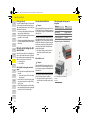
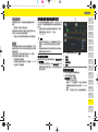
Porsche Home Energy Manager Yükleme Rehberi
- Tip
- Yükleme Rehberi

Porsche Home Energy Manager
9Y0.915.686/.A/.B/.C/.D/.E
ROW
01_IA_Umschlag.fm Seite 0 Dienstag, 20. August 2019 2:18 14

US
Porsche Home Energy Manager
Installation Manual.............................. 1
FC
Porsche Home Energy Manager
Manuel technique .............................16
ESM
Porsche Home Energy Manager
Installation Manual............................31
PTB
Porsche Home Energy Manager
Manual de instalação ....................... 46
TR
Porsche Home Energy Manager
Kurulum Talimatları ...........................62
RU
Porsche Home Energy Manager
Инструкция по установке..............77
UK
Porsche Home Energy Manager
Посібник зі встановлення..............93
VIE
Porsche Home Energy Manager
Hướng dẫn lắp đặt................... 108
HE
Porsche Home Energy Manager
xxxxxxxxxxx.................................... 123
AR
Porsche Home Energy Manager
xxxxxxxxx........................................ 138
JPN
Porsche Home Energy Manager
xxxxxxxxxxxxxxxxxx.................... 153
KOR
Porsche Home Energy Manager
xxxxxxxxxx...................................... 168
CHS
Porsche Home Energy Manager
xxxxxxxx .......................................... 183
CHT
Porsche Home Energy Manager
xxxxxxxx
.......................................... 198
THA
Porsche Home Energy Manager
I
........................................................... 212
Ҿጎ֩
৾ͤັ̫ζΣνͺσ
ʤʰʷʺʤʪʩʸʣʮ
¼n¤º°µ¦·´Ê
Ԋ၆Йы
SprachVerz_Instal_ROW.fm Seite 1 Freitag, 23. August 2019 2:36 14

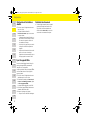
1
Table of Contents
English USA
Applicable documents ..................................................3
Basic safety principles ..................................................3
Qualification of personnel................................................3
Notes on installation..........................................................3
Overview ..........................................................................4
Installation version 1 .........................................................4
Installation version 2 .........................................................5
Installation version 3 .........................................................5
Displays and controls ........................................................6
Overview of device connections ....................................7
Installation and connection .........................................7
Connection to the power supply....................................7
Connection to the building installation........................9
Initial Operation ...........................................................12
Setup .............................................................................12
Accessing the web application via the hotspot......12
Using the setup assistant ............................................12
Configuring home installation......................................13
Adding an EEBus device................................................13
Checking function...........................................................13
Technical Data .............................................................14
Index ..............................................................................15
9Y0071723_1907_inst_ROW_US.book Seite 1 Donnerstag, 22. August 2019 1:38 13

2
US
FC
ESM
PTB
TR
RU
UK
VIE
HE
AR
JPN
KOR
CHS
CHT
THA
Porsche, the Porsche Crest, Panamera,
Cayenne and Taycan are registered trademarks
of Dr. Ing. h.c. F. Porsche AG.
Printed in Germany.
Reprinting, even of excerpts, or duplication of
any type is only permissible with the written
authorisation of Dr. Ing. h.c. F. Porsche AG.
© Dr. Ing. h.c. F. Porsche AG
Porscheplatz 1
70435 Stuttgart
Germany
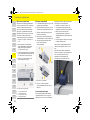
Installation Manual
Please keep the Installation Manual in a safe place.
These instructions are intended for persons
entrusted with or responsible for installing, starting
up and maintenance of the energy manager.
Always pay attention to the warning and safety
instructions in this booklet. The manufacturer cannot
be held liable in the event of improper handling
contrary to these instructions.
In addition, the approval conditions of the supplied
accessories must be observed, complied with, and
followed.
Further instructions
You can find information on operating the energy
manager in the operating instructions. Pay particular
attention to the warning and safety instructions.
Suggestions
Do you have any questions, suggestions or ideas
regarding these instructions?
Please write to us:
Dr. Ing. h.c. F. Porsche AG
Vertrieb Customer Relations
Porscheplatz 1
70435 Stuttgart
Germany
Equipment
Porsche is entitled to discrepancies between actual
equipment and technology and versions illustrated
and described in these instructions, on the grounds
of continuous further development. Items of
equipment are sometimes optional or vary depending
on the country in which the vehicle is sold. For more
information on retrofit equipment, please contact
your Porsche partner.
Warnings and symbols
Various types of warnings and symbols are used in
this manual.
b Conditions that must be met in order to use a
function.
e Instruction that you must follow.
1. If an instruction comprises several steps, these
are numbered.
f Notice on where you can find further important
information on a topic.
Article number Time of printing
9Y0.071.723-ROW 07/2019
DANGER
Serious injury or death
Failure to observe warnings in the “Danger” category
will result in serious injury or death.
WARNING
Possible serious injury or
death
Failure to observe warnings in the “Warning”
category can result in serious injury or death.
CAUTION
Possible moderate or
minor injury
Failure to observe warnings in the “Caution” category
can result in moderate or minor injuries.
NOTICE
Failure to observe warnings in the “Notice” category
can result in damage.
Information
Additional information is indicated by “Information”.
9Y0071723_1907_inst_ROW_S.book Seite 2 Donnerstag, 22. August 2019 1:38 13

3
Applicable documents
US
FC
ESM
PTB
TR
RU
UK
VIE
HE
AR
JPN
KOR
CHS
CHT
THA
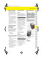
Applicable documents
Basic safety principles
Qualification of personnel
The electrical installation may only be performed by
persons with the relevant knowledge of electrical/
electronic equipment (electrician). These persons
must provide proof that they have the specialist
knowledge required to install electrical systems in
the form of an examination certificate.
Improper installation can endanger your own life and
that of others.
Requirements for the electrician performing the
installation:
– Ability to evaluate test results
– Knowledge of IP ratings and their use
– Knowledge about fitting of electrical installation
material
– Knowledge of the applicable electrical/electronic
and national regulations
– Knowledge of fire safety measures and general
and specific safety and accident prevention
regulations
– Ability to select suitable tools, testers and,
if necessary, personal protective equipment,
as well as the electrical installation materials for
ensuring tripping conditions
– Knowledge of the type of electricity network
(TN, IT and TT System) and the resulting
connection requirements (protective ground,
grounding without a PE conductor, additional
measures necessary)
Notes on installation
Electrical installation must be performed in such
a way that:
– Protection from contact in accordance with
locally applicable regulations is ensured at all
times for the entire electrical installation.
– Locally applicable fire safety regulations are
complied with at all times.
– Displays, controls and USB ports of the energy
manager are accessible to the customer without
restriction and ensure protection from contact
with live parts.
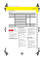
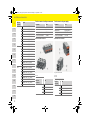
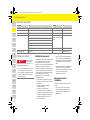
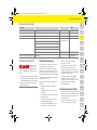
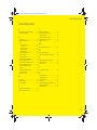
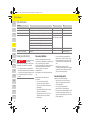
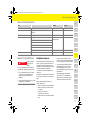
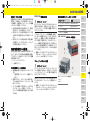
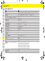
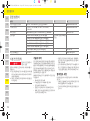
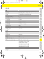
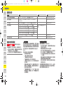
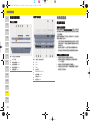
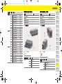
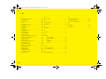
Description Type Note Info
External mains power supply unit STEP-PS/ 1AC/24DC/0.75, article number 2868635 www.phoenixcontact.com
Push-on connector 2x1754571, 1x1790108, 1x1790111, 3x1790124, 1x1939439 www.phoenixcontact.com
WiFi antenna
HiRO H50284 wireless 802.11n 2.4GHz WiFi gain 2dBi OMNI www.hiroinc.com
Current sensors EChun ECS1050-L40P (50 A input; 33.3 mA output) All Echun models have
a 33 mA output
www.echun-elc.com
EChun ECS16100-L40M (100A input; 33.3 mA output)
EChun ECS24200-L40G (200A input; 33.3 mA output)
EChun ECS36400-L40R (400A input; 33.3 mA output)
EChun ECS36600-L40N (600A input; 33.3 mA output)
TT 100-SD (LEM, 100 A input; 33.33 mA output) www.lem.com
Wall-mounted distribution box 733414911 www.spelsberg.com
DANGER
Danger to life due to
electrical voltage!
Injuries due to electric shock and/or burns, possibly
resulting in death, are possible.
e During all work, make sure at all times that power
to the system is switched off and secured so it
cannot inadvertently be switched on.
e Do not open the housing of the energy manager
under any circumstances.
9Y0071723_1907_inst_ROW_US.book Seite 3 Donnerstag, 22. August 2019 1:38 13

4
Overview
US
FC
ESM
PTB
TR
RU
UK
VIE
HE
AR
JPN
KOR
CHS
CHT
THA
– The maximum permitted cable length of 9.8 ft.
(3 m) per current sensor is complied with.
– The voltage measurement and external power
supply inputs and energy manager relays are
adequately fused.
– The correct length and product-specific bending
radii are complied with when laying installation
cables.
If the installation environment requires Overvoltage
Category III (OVCIII), the input side of the external
power supply must be protected by means of
protective circuitry (e.g. a varistor) that conforms to
locally applicable regulations.
Installation at high altitude
Sensor supply cables that are installed in electrical
installations at a height of over 6,600 ft. (2,000 m) or
must conform to Overvoltage Category III (OVCIII)
due to their installation location must additionally be
insulated using heat-shrink tubing or suitable
insulation tubing with a dielectric strength of
508 V/mil (20 kV/mm) and minimum wall thickness
of 0.016 in. (0.4 mm) along the entire length of cable
between the sensor output (housing) and the input
terminal on the energy manager.
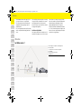
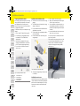
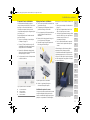
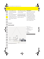
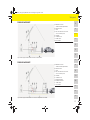
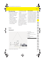
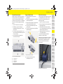
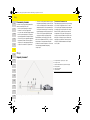
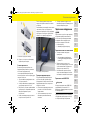
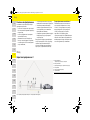
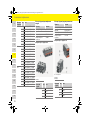
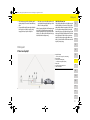
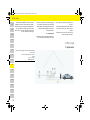
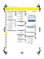
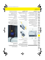
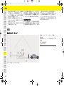
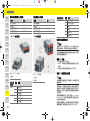
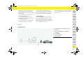
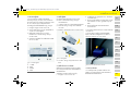
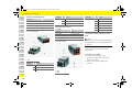
Overview
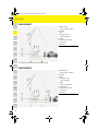
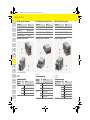
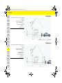
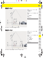
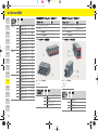
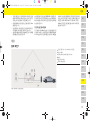
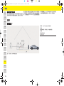
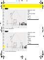
Installation version 1
A Power supply (1 to 3 phases, 1-phase supply here)
B Electricity meter
C Current sensor(s) (1 current sensor per phase)
D Distribution
E Power consumers in the home
F EEBus protocol
Fig. 1: Installation example: Simple home installation
9Y0071723_1907_inst_ROW_S.book Seite 4 Donnerstag, 22. August 2019 1:38 13

5
Overview
US
FC
ESM
PTB
TR
RU
UK
VIE
HE
AR
JPN
KOR
CHS
CHT
THA
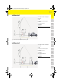
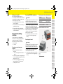
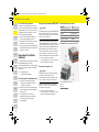
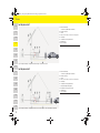
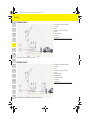
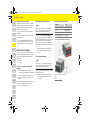
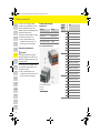
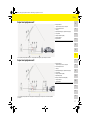
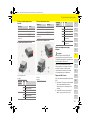
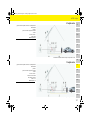
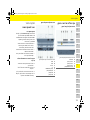
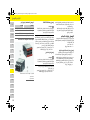
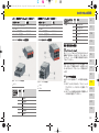
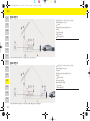
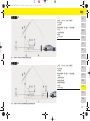
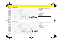
Installation version 2
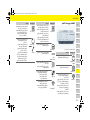
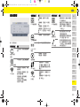
Installation version 3
A Power supply (1 to 3 phases, 1-phase supply here)
B Photovoltaic
C Inverter
D Current sensor(s) (1 current sensor per phase)
E Distribution
F Power consumers in the home
G Electricity meter
H EEBus protocol
Fig. 2: Installation example: Simple home installation with photovoltaic system
A Power supply (1 to 3 phases, 1-phase supply here)
B Photovoltaic
C Inverter
D Current sensor(s) (1 current sensor per phase)
E Distribution
F Power consumers in the home
G Sub distribution
H Power consumers outside the home
I Electricity meter
J EEBus protocol
Fig. 3: Installation example: Simple home installation with photovoltaic system and sub-distribution box
9Y0071723_1907_inst_ROW_US.book Seite 5 Donnerstag, 22. August 2019 1:38 13

6
Overview
US
FC
ESM
PTB
TR
RU
UK
VIE
HE
AR
JPN
KOR
CHS
CHT
THA
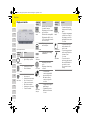
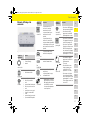
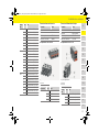
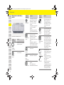
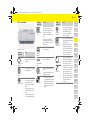
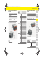
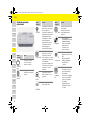
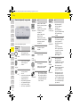
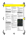
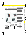
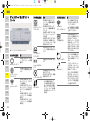
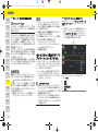
Displays and controls
Fig. 4: Displays and controls
Symbol and
meaning
Description
On/Off status
LED lights up green: energy
manager is ready for operation
Internet status
LED lights up green: internet
connection established
WiFi status
LED flashes blue: hotspot mode,
no client connected
LED lights up blue: hotspot mode,
at least one client connected
LED flashes green: client mode,
no WiFi connection available
LED lights up green: client mode,
WiFi connection available
PLC network
status
LED flashes green: searching for
PLC network connection.
LED lights up green: PLC network
connection in place.
LED flashes blue: activating DHCP.
LED lights up blue: DHCP (solely
for PLC) is active and PLC network
connection is in place.
Ethernet status
LED lights up green: network
connection in place
RS485/
CAN status
On: LED lights up green during
communication
Error status
LED lights up yellow: there is
an error
LED lights up red: functioning
is restricted
WPS button
e To establish a WiFi
connection using the WPS
function, briefly press the
WPS button (network
connection only possible
as a client).
WiFi button
(hotspot)
e To enable WiFi, briefly press
the WiFi button.
e To disable WiFi, press the
WiFi button for more than
1 second.
Symbol and
meaning
Description
PLC pairing
button
e To enable the PLC pairing,
briefly press the PLC pairing
button.
e To enable the energy manager
as a DHCP server (solely for
PLC pairings), press the PLC
pairing button for more than
10 seconds.
Reset button
e To restart the device, press
the Reset button for less
than 5 seconds.
e To reset the passwords, press
the Reset and CTRL buttons
for between 5 and
10 seconds.
e To restore the device to
the factory settings, press the
Reset and CTRL buttons for
more than 10 seconds.
This overwrites all current
settings.
CTRL button
Symbol and
meaning
Description
9Y0071723_1907_inst_ROW_S.book Seite 6 Donnerstag, 22. August 2019 1:38 13

7
Installation and connection
US
FC
ESM
PTB
TR
RU
UK
VIE
HE
AR
JPN
KOR
CHS
CHT
THA
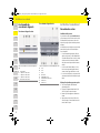
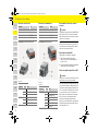
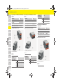
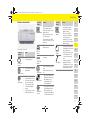
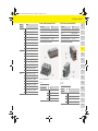
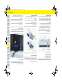
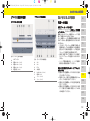
Overview of device connections
Connections on top of device
Fig. 5: View of connections on top of the device
Connections on underside of device
Fig. 6: View of connections on underside of the device
Installation and connection
Connection to the power supply
Installing circuit breakers
The energy manager does not have any internal
fuses. Therefore, the voltage measurement and
external power supply inputs and relays must be
protected with suitable fuses.
Line protection fuses are not included in the scope of
supply and must be installed by an electrician.
– Operation of the energy manager requires
overcurrent protection for all supply cables.
Here, it is important to select fuses with a
sensitive trip characteristic.
– Fuses must be selected based on the
commercially available components in the
country of use.
– Use components with the lowest tripping current
and shortest tripping time.
Installation of optional wall-mounted
distribution box
e Pay attention to the installation instructions for
the wall-mounted distribution box.
e Adhere to the maximum permitted cable length
of 9.8 ft. (3 m) per current sensor.
e Firmly secure the wall-mounted distribution box
to a wall.
e Before installing the wall-mounted distribution
box, check whether there are any electric cables
in the area where you will be drilling.
A
WiFi antenna
B Current sensors (J301)
C Current sensors (J300)
D Current sensors (J200)
E Voltage measurement (J400)
A USB
B USB
C ETH 0
D not used
E RS485/CAN (J1000)
F Power supply (J102)
G Relay (J900)
H Relay (J901)
9Y0071723_1907_inst_ROW_US.book Seite 7 Donnerstag, 22. August 2019 1:38 13

8
Installation and connection
US
FC
ESM
PTB
TR
RU
UK
VIE
HE
AR
JPN
KOR
CHS
CHT
THA
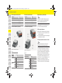
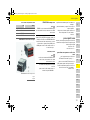
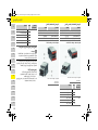
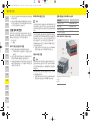
Preparing the distribution cabinet
If the installation environment requires Overvoltage
Category III (OVCIII), the input side of the external
power supply must be protected by means of
protective circuitry (e.g. a varistor) that conforms to
locally applicable regulations.
For information on the space needed by the energy
manager:
f Refer to chapter "Technical Data" on page 14.
e For installation, the energy manager requires
horizontal pitch 11.5 on a DIN rail in the
distribution box.
e Install the power supply unit of the energy
manager at a minimum distance of horizontal
pitch 0.5 from the energy manager housing.
e Protect all electrical interfaces from direct/
indirect contact.
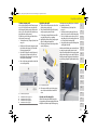
Fig. 7: Preparing the distribution cabinet
Installation in the distribution cabinet
b All cable connections are connected to the energy
manager.
b The DIN rail holder on the housing of the energy
manager is unfastened.
1. Position the DIN rail holder on the DIN rail in the
distribution box at an incline.
2. Tilt the housing of the energy manager and place
it level on the DIN rail.
3. Fasten the DIN rail holder on the housing of the
energy manager.
Fig. 8: Installation in the distribution cabinet
4. Check that the energy manager is firmly secured
to the DIN rail.
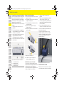
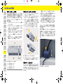
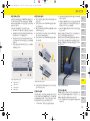
Installing the current sensors
Install the current sensors for measuring the overall
current of the business/household after installing the
main fuse on the relevant main phases. The energy
flows must not yet have been divided into further
sub-circuits.
f Refer to chapter "Overview" on page 4.
e Adhere to the maximum permitted cable length
of 9.8 ft. (3 m) per current sensor.
e Select an installation location where cables can
run straight and pay attention to the direction of
measurement (arrow pointing towards the power
consumer).
e Insert the installation cable in the current sensor
and close the cap of the sensor.
If sensor cables need to be extended, use the same
type of cable if possible.
If the installation environment requires the use of the
optional wall-mounted distribution box, the cables
must be routed to the distribution box through
suitable cable routing systems (empty conduits,
cable ducts, etc.).
Fig. 9: Current sensor installation example
A Horizontal pitch 11.5
B Horizontal pitch 9
C Horizontal pitch 0.5
D Horizontal pitch 2
9Y0071723_1907_inst_ROW_S.book Seite 8 Donnerstag, 22. August 2019 1:38 13

9
Installation and connection
US
FC
ESM
PTB
TR
RU
UK
VIE
HE
AR
JPN
KOR
CHS
CHT
THA
Routing connecting cables
Before installing any equipment, route the
connecting cables inside the distribution cabinet in
accordance with local regulations, and protect all
electrical interfaces from contact.
e Use suitable installation cables in accordance
with local regulations.
e Cut installation cables to suit the available space
and installation locations.
e Ensure installation cables comply with the
product-specific bending radii, to prevent faults
in cables and hardware.
Connection to the building
installation
Connect all devices to the existing building
installation in accordance with locally applicable
regulations and standards. The following
abbreviations are used in these instructions:
– N = neutral wire
– L = live wire
Connecting an external mains power
supply unit
e Follow the manufacturer's installation
instructions.
f Refer to chapter "Applicable documents" on
page 3.
e Connect the DC output to the energy manager in
accordance with the pin assignment of the power
supply connector (J102).
e Connect the power supply unit to the energy
manager using a cable. This cable must be
produced by an electrician.
Connecting RS485/CAN communication
When connecting the energy manager to the building
installation, there is a risk that DC power supply
connectors (J102) may be inadvertently plugged into
the RS485/CAN port. This can damage the energy
manager. Insert the six-pole connector without
connection cable (J1000) that was included with
delivery, to prevent confusion.
e Insert the connector without connection cable
into socket J1000 in the energy manager
housing.
Connecting relay channels
The energy manager is delivered with a suitable
connector without connection cable.
e Insert the connector without connection cable
into socket J900/J901 in the energy manager
housing.
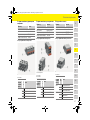
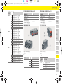
Push-on connector for current measurement
Overview of J200/J300/J301 connectors
Fig. 10: Overview of J200/J300/J301
Information
The software 08/2019 does not allow for connection
to RS485/CAN. For future features, please pay
attention to information on new software releases.
Information
The software 08/2019 does not allow for connection
to relay channels. For future features, please pay
attention to information on new software releases.
Parameter Value
Push-on connector J200/J300/J301
Manufacturer Phoenix Contact
Socket part number 1766369
Connector part number 1939439
1 Pin 1
2 Pin 2
9Y0071723_1907_inst_ROW_US.book Seite 9 Donnerstag, 22. August 2019 1:38 13

10
Installation and connection
US
FC
ESM
PTB
TR
RU
UK
VIE
HE
AR
JPN
KOR
CHS
CHT
THA
Push-on connector for voltage measurement
Overview of J400 connectors
Fig. 11: Overview of J400
Push-on connector for power supply
Overview of J102 connectors
Fig. 12: Overview of J102
Push-on
connector
Pin Signal
J200 1 Current sensor 1 ("l", black)
2 Current sensor 1 ("k", white)
3 Current sensor 2 ("l", black)
4 Current sensor 2 ("k", white)
5 Current sensor 3 ("l", black)
6 Current sensor 3 ("k", white)
7 Current sensor 4 ("l", black)
8 Current sensor 4 ("k", white)
J300 1 Current sensor 5 ("l", black)
2 Current sensor 5 ("k", white)
3 Current sensor 6 ("l", black)
4 Current sensor 6 ("k", white)
5 Current sensor 7 ("l", black)
6 Current sensor 7 ("k", white)
7 Current sensor 8 ("l", black)
8 Current sensor 8 ("k", white)
J301 1 Current sensor 9 ("l", black)
2 Current sensor 9 ("k", white)
3 Current sensor 10 ("l", black)
4 Current sensor 10 ("k", white)
5 Current sensor 11 ("l", black)
6 Current sensor 11 ("k", white)
7 Current sensor 12 ("l", black)
8 Current sensor 12 ("k", white)
Parameter Value
Push-on connector J400
Manufacturer Phoenix Contact
Socket part number 1766369
Connector part number 939439
1 Pin 1
Push-on
connector
Pin Signal
J400 1 Neutral wire N
2 Live L1
3 Phase L2
4 Phase L3
Parameter Value
Push-on connector J102
Manufacturer Phoenix Contact
Socket part number 1786837
Connector part number 1790108
1 Pin 1
2 Pin 2
Push-on
connector
Pin Signal
J102 1 Power supply +24 V
2 Earth
3 Power supply +24 V
4 Earth
9Y0071723_1907_inst_ROW_S.book Seite 10 Donnerstag, 22. August 2019 1:38 13

11
Installation and connection
US
FC
ESM
PTB
TR
RU
UK
VIE
HE
AR
JPN
KOR
CHS
CHT
THA
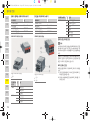
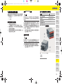
Push-on connector for relay contact
Overview of J900/J901 connectors
Fig. 13: Overview of J900/J901
Push-on connector for communication
Overview of J1000 connectors
Fig. 14: Overview of J1000
Connecting current and voltage measurement
The current and voltage measurement channels are
connected via several connectors. The required
connector is included in the scope of delivery of the
energy manager.
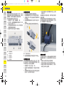
Connecting the WiFi antenna
The WiFi antenna is used to boost the WiFi signal.
1. Connect the WiFi antenna to the plug/screw
connection on the energy manager.
2. Secure the WiFi antenna outside the distribution
box using the magnetic base.
Checking the signal quality of the PLC network
To check the connection quality of the PLC network,
you can find out the PLC transmission rate via the
household electrical system using software and
Ethernet PLC converters. To do this, connect the
Parameter Value
Push-on connector J900/J901
Manufacturer Phoenix Contact
Socket part number 1757255
Connector part number 1754571
1 Pin 1
Push-on
connector
Pin Signal
J900 1 NO contact
2 COM contact
3 NC contact
J901 1 NO contact
2 COM contact
3 NC contact
Parameter Value
Push-on connector J1000
Manufacturer Phoenix Contact
Socket part number 1786840
Connector part number 1790111
1 Pin 1
2 Pin 2
Push-on
connector
Pin Signal
J1000 1 RS485 signal B –
2 RS485 signal A +
3 Earth
4 Earth
5 CAN Low
6 CAN High
Information
The software 08/2019 does not allow for connection
to RS485/CAN. For future features, please pay
attention to information on new software releases.
Information
The software and Ethernet PLC converter described
in this section are not in the scope of delivery.
9Y0071723_1907_inst_ROW_US.book Seite 11 Donnerstag, 22. August 2019 1:38 13

12
Initial Operation
US
FC
ESM
PTB
TR
RU
UK
VIE
HE
AR
JPN
KOR
CHS
CHT
THA
converters to the mains supply at the installation
locations.
Select the installation location of the energy manager
and of the power consumers with PLC functionality
(such as the Porsche Mobile Charger Connect) as
installation locations for this.
The actual transmission rate between the installation
locations can be displayed with the aid of evaluation
software. Transmission rates of 100 Mbit or more are
sufficient.
Initial Operation
When the power supply is on, the energy manager is
switched on and ready for operation:
To ensure the energy manager functions reliably and
with its full range of functions, the latest software
must be installed.
e After startup, perform a software update using
the web application.
Setup
The energy manager is set up via a web application.
On this web application, all the necessary values can
be entered and the current sensors configured.
Charging equipment that supports this function can
be added as an EEBus device.
The following information may be required to set up
the energy manager:
– Access data for the home network
– Access data for the user profile (for linking to the
Porsche ID)
– Information on electricity tariffs/prices
Accessing the web application via
the hotspot
The web application can be opened on a device
(PC, tablet or smartphone) via a hotspot established
by the energy manager.
e To open the web application when the hotspot
has been enabled, enter the following IP address
in the address bar of your browser: 192.168.9.11
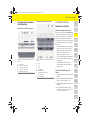
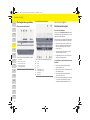
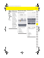
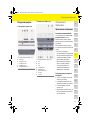
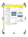
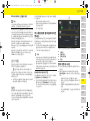
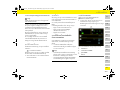
Logging on to the web application
Two users are available for logging on to the web
application: HOME USER and CUSTOMER SERVICE.
e To set up the energy manager, log on to the
energy manager web application as CUSTOMER
SERVICE. The initial passwords can be found in the
access data letter.
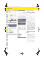
Fig. 15: Energy manager web application (OVERVIEW)
Using the setup assistant
b Logged on to the web application as customer
service.
e Proceed as directed by the setup assistant.
The SETUP ASSISTANT covers the following points,
among others:
– Settings for updates and security measures
– Establishing a network connection via WiFi,
Ethernet or PLC
– Linking the energy manager to a user profile
(Porsche ID)
– Entering tariff information for the "Cost-
optimized charging" function
On/Off status lights up green.
Information
– Depending on which browser you are using, the
web application will not open immediately, but
information about the browser's security settings
will be displayed first.
– The manner of entering the network key for
calling up the web application depends on the
device's operating system.
A
POWER SOURCES
B
CURRENT FLOW
C
POWER CONSUMER
D
POWER
9Y0071723_1907_inst_ROW_S.book Seite 12 Donnerstag, 22. August 2019 1:38 13

13
Setup
US
FC
ESM
PTB
TR
RU
UK
VIE
HE
AR
JPN
KOR
CHS
CHT
THA
Configuring home installation
b Logged on to the web application as customer
service.
e Configure the home installation.
HOME SETUP covers the following points,
among others:
– Configuring the energy manager for the
mains, power sources, current sensors and
power consumers
– Prioritizing and managing charging
operations when several chargers are used
– Enabling and disabling functions such as
"Overload protection", "Self-consumption
optimization" and "Cost-optimized charging"
Adding an EEBus device
To ensure the energy manager functions correctly, it
is vital to connect it to an EEBus device, such as the
Porsche Mobile Charger Connect, for example.
If the energy manager and EEBus device are in the
same network, they can be connected.
b Logged on to the web application as home user or
customer service.
1. To start connection, click ADD EEBUS DEVICE in
HOME SETUP > POWER CONSUMER.
Available EEBus devices are displayed.
2. Select the EEBus device via the name and
Identification number (SKI).
3. Start the connection on the charger.
f Pay attention to the charger operating
instructions.
Checking function
e Using the web application, make sure the energy
manager is functioning correctly. To do so, check
that plausible values for the power sources and
consumers are displayed on the OVERVIEW screen.
9Y0071723_1907_inst_ROW_US.book Seite 13 Donnerstag, 22. August 2019 1:38 13

14
Technical Data
US
FC
ESM
PTB
TR
RU
UK
VIE
HE
AR
JPN
KOR
CHS
CHT
THA
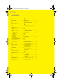
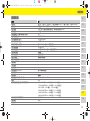
Technical Data
Description Value
Ports 2 x USB, 1 x PLC, 1 x WiFi, 1 x Ethernet (ETH 0), 12 x CT input, 1 x RS485/CAN
Space requirement Horizontal pitch 11.5 (1 HP is equivalent to 0.7 inches/17.5 – 18 mm)
Current measurement 0.5 A to 600 A (depending on current sensor), maximum cable length 9.8 ft. (3 m)
Voltage measurement 100 V to 240 V (AC)
Maximum length of supply cable to USB port 9.8 ft. (3 m)
Energy manager input 24 V (DC)/0.75 A
External power supply (input) 100 V to 240 V (AC)
External power supply (output) 24 V (DC)/18 W
Relay (voltage/load) Maximum 250 V (AC), maximum 3 A resistive load
Temperature range Storage temperature –40 °F to +158 °F (–40 °C to +70 °C)
Temperature range Operating temperature –4 °F to +113 °F (–20 °C to +45 °C) (at 10 % to 90 % air humidity)
Type of article under test Control unit,
Description of device function Charge management for households
Connection to the power supply External power supply unit
Installation/overvoltage category III
Measurement category III
Degree of contamination 2
Type of protection IP20
Protection class to IEC 60529 DIN rail-mounted device
Protection class 2
Operating conditions Continuous operation
Overall size of device (width x depth x height) 6.3 in. x 3.6 in. x 2.9 in. (159.4 mm x 90.2 mm x 73.2 mm)
Weight 0.7 lbs (0.3 kg)
External current sensor (accessory and removable part) ECS1050-L40P (EChun; 50 A input; 33.3 mA output)
ECS16100-L40M (EChun; 100A input; 33.3 mA output)
TT 100-SD (LEM, 100 A input; 33.33 mA output)
ECS24200-L40G (EChun; 200A input; 33.3 mA output)
ECS36400-L40R (EChun; 400A input; 33.3 mA output)
ECS36600-L40N (EChun; 600A input; 33.3 mA output)
Antenna (accessory and removable part) HIRO H50284
Transmission frequency bands 2.4 GHz
Transmission power 58.88 mW
9Y0071723_1907_inst_ROW_S.book Seite 14 Donnerstag, 22. August 2019 1:38 13

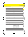
15
Index
Index
A
Accessing the web application via the hotspot............................. 12
Adding an EEBus device....................................................................... 13
Applicable documents.............................................................................3
Applicable standards/directives........................................................ 14
Article number of instructions............................................................... 2
B
Basic safety principles............................................................................. 3
C
Checking function.................................................................................. 13
Circuit-breaker........................................................................................... 7
Configuring home installation ............................................................ 13
Connecting an external mains power supply unit............................9
Connecting relay channels ..................................................................... 9
Connecting RS485/CAN communication ......................................... 9
Connecting the WiFi antenna............................................................. 11
Connection to the building installation............................................... 9
Connection to the power supply...........................................................7
Connections on top of device................................................................7
Connections on underside of device.................................................... 7
D
Displays and controls............................................................................... 6
I
Initial Operation ...................................................................................... 12
Installation and connection....................................................................7
Installation at high altitude..................................................................... 4
Installation in the distribution cabinet ................................................ 8
Installation version 1................................................................................ 4
Installation version 2................................................................................ 5
Installation version 3................................................................................ 5
Installing the current sensors................................................................ 8
L
Logging on to the web application.................................................... 12
N
Notes on installation ................................................................................3
O
Overview...................................................................................................... 4
Overview and specification.................................................................... 4
Overview of device connections........................................................... 7
P
Preparing the distribution cabinet .......................................................8
Product maintenance.............................................................................14
Push-on connector
Communication.............................................................................10
Current measurement................................................................... 9
Power supply .................................................................................10
Relay contact.................................................................................10
Voltage measurement.................................................................10
Q
Qualification of personnel.......................................................................3
R
Routing connecting cables..................................................................... 9
S
Scope of supply......................................................................................... 7
Setup ..........................................................................................................12
Signal quality............................................................................................11
T
Technical data..........................................................................................14
U
Using the setup assistant.....................................................................12
W
Wall-mounted distribution box............................................................. 7
9Y0071723_1907_inst_ROW_US.book Seite 15 Donnerstag, 22. August 2019 1:38 13

16
Table des matières
Français (Canada)
Documents applicables .............................................18
Principes de sécurité ..................................................18
Qualification du personnel ............................................18
Remarques concernant l’installation..........................18
Vue d’ensemble ...........................................................19
Variante d’installation 1.................................................19
Variante d’installation 2.................................................20
Variante d’installation 3.................................................20
Éléments d’affichage et de commande.....................21
Vue d’ensemble des raccordements d’appareils ....22
Installation et raccordement ....................................22
Raccordement au secteur.............................................22
Raccordement à l’installation du bâtiment ..............24
Mise en service ............................................................27
Configuration ...............................................................27
Ouverture de l’application Web via
un point d’accès...............................................................27
Exécution de l’assistant d’installation .......................27
Configuration de l’installation à domicile..................28
Ajout d’un appareil EEBus .............................................28
Contrôle de fonctionnement ........................................28
Caractéristiques techniques .....................................29
Index alphabétique .....................................................30
9Y0071723_1907_inst_ROW_.book Seite 16 itto, 21. August 2019 5:08 17

17
US
FC
ESM
PTB
TR
RU
UK
VIE
HE
AR
JPN
KOR
CHS
CHT
THA
Porsche, l’écusson Porsche, Panamera,
Cayenne et Taycan sont des marques déposées
par Dr. Ing. h.c. F. Porsche AG.
Printed in Germany.
Toute reproduction, même partielle, par quelque pro-
cédé que ce soit, est interdite sans l’autorisation écrite
préalable de la société Dr. Ing. h.c. F. Porsche AG.
© Dr. Ing. h.c. F. Porsche AG
Porscheplatz 1
70435 Stuttgart
Allemagne
Guide d’installation
Conservez le guide d’installation.
Le présent guide s’adresse aux personnes auxquelles
sont confiées l’installation, la mise en service et la
maintenance du gestionnaire d’énergie ou qui en sont
responsables.
Respectez systématiquement les avertissements et
les consignes de sécurité de ce guide. Le fabricant
décline toute responsabilité en cas de manipulation
incorrecte contraire aux informations contenues
dans ce guide.
Par ailleurs, il convient également d’observer, de
respecter et de suivre les conditions d’homologation
des accessoires fournis.
Autres notices et guides
Vous trouverez des informations sur l’utilisation du
gestionnaire d’énergie dans la notice d’utilisation.
Respectez tout particulièrement les avertissements
et les consignes de sécurité.
Suggestions
Avez-vous des questions, des remarques ou
des idées concernant le présent guide?
N’hésitez pas à nous écrire:
Dr. Ing. h.c. F. Porsche AG
Vertrieb Customer Relations
Porscheplatz 1
70435 Stuttgart
Allemagne
Équipement
Du fait de l’amélioration constante des produits,
Porsche se réserve le droit d’apporter des modifica-
tions aux équipements et à leur conception tech-
nique par rapport aux illustrations et descriptions
contenues dans ce guide. Les variantes d’équipe-
ment ne font pas toujours partie de l’équipement
de série ou sont fonction de l’équipement spécifique
au pays. Pour de plus amples informations sur les
possibilités de montage ultérieur, adressez-vous à un
concessionnaire Porsche.
Avertissements et symboles
Différents types d’avertissements et de symboles
sont utilisés dans ce manuel.
b Conditions devant être réunies pour utiliser une
fonction.
e Instruction que vous devez respecter.
1. Les instructions sont numérotées lorsque
plusieurs étapes se suivent.
f Remarque indiquant où vous pouvez trouver des
informations supplémentaires concernant un
thème.
Référence Mise sous presse
9Y0.071.723-ROW 07/2019
DANGER
Blessures graves ou
mortelles
Le non-respect des avertissements de la catégorie
«Danger» entraîne des blessures graves ou mortelles.
AVERTISSEMENT
Blessures graves ou
mortelles possibles
Le non-respect des avertissements de la catégorie
«Avertissement» peut entraîner des blessures graves
ou mortelles.
MISE EN GARDE
Blessures moyennement
graves ou légères
possibles
Le non-respect des avertissements de la catégorie
«Mise en garde» peut entraîner des blessures
moyennement graves ou légères.
AVIS
Le non-respect des avertissements de la catégorie
«Avis» peut entraîner des dégâts matériels.
Information
Les informations supplémentaires sont indiquées par
le mot «Information».
04_Impressum.fm Seite 17 Donnerstag, 22. August 2019 10:42 10

18
Documents applicables
US
FC
ESM
PTB
TR
RU
UK
VIE
HE
AR
JPN
KOR
CHS
CHT
THA
Documents applicables
Principes de sécurité
Qualification du personnel
L’installation électrique ne doit être effectuée que par
des personnes possédant les connaissances
électrotechniques nécessaires (électriciens
qualifiés). Ces personnes doivent démontrer qu’elles
possèdent les connaissances spécialisées
nécessaires à l’installation des systèmes électriques
et de leurs composants en réussissant un examen.
Une installation incorrecte peut mettre en danger
la vie de l’installateur et celle des autres.
Exigences vis-à-vis de l’électricien qualifié
effectuant l’installation:
– Capacité d’évaluer les résultats des mesures
– Connaissance des classes de protection IP et de
leur application
– Connaissance du montage du matériel
d’installation électrique
– Connaissance des réglementations
électrotechniques et nationales applicables
– Connaissance des mesures de protection contre
l’incendie et des réglementations générales et
spécifiques en matière de sécurité et de
prévention des accidents
– Capacité de choisir l’outil, l’équipement de me-
sure et, le cas échéant, l’équipement de protec-
tion individuelle et le matériel d’installation élec-
trique appropriés pour assurer les conditions
d’arrêt
– Connaissance du type de réseau d’alimentation
(système TN, IT et TT) et des conditions de
branchement en résultant (mise à zéro classique,
mise à la terre temporaire, mesures
supplémentaires nécessaires)
Remarques concernant
l’installation
L’installation électrique doit être réalisée de telle
sorte que:
– la protection contre les contacts de toute
l’installation électrique est assurée à tout
moment conformément aux dispositions en
vigueur sur place.
Description Type Remarque Info
Bloc d’alimentation externe STEP-PS/ 1 CA/24 CC/0.75, référence article 2868635 www.phoenixcontact.com
Connecteur 2 x 1754571, 1 x 1790108, 1 x 1790111, 3 x 1790124, 1 x 1939439 www.phoenixcontact.com
Antenne WiFi HiRO H50284 Wireless 802.11n 2.4 GHz WiFi Gain 2dBi OMNI www.hiroinc.com
Capteurs de courant EChun ECS1050-L40P (entrée 50 A; sortie 33,3 mA) Tous les types Echun
respectivement avec Output
33 mA
www.echun-elc.com
EChun ECS16100-L40M (entrée 100 A; sortie 33,3 mA)
EChun ECS24200-L40G (entrée 200 A; sortie 33,3 mA)
EChun ECS36400-L40R (entrée 400 A; sortie 33,3 mA)
EChun ECS36600-L40N (entrée 600 A; sortie 33,3 mA)
TT 100-SD (LEM, entrée 100 A; sortie 33,33 mA) www.lem.com
Répartiteur apparent 733414911 www.spelsberg.com
DANGER
Danger de mort lié à la
tension électrique!
Risque de blessures par choc électrique et / ou
brûlures pouvant entraîner la mort!
e Veillez à ce que l’installation soit toujours hors
tension et protégée contre toute mise sous
tension involontaire pendant tous les travaux.
e N’ouvrez sous aucun prétexte le boîtier du
gestionnaire d’énergie.
9Y0071723_1907_inst_ROW_.book Seite 18 itto, 21. August 2019 5:08 17
Sayfa yükleniyor...
Sayfa yükleniyor...
Sayfa yükleniyor...
Sayfa yükleniyor...
Sayfa yükleniyor...
Sayfa yükleniyor...
Sayfa yükleniyor...
Sayfa yükleniyor...
Sayfa yükleniyor...
Sayfa yükleniyor...
Sayfa yükleniyor...
Sayfa yükleniyor...
Sayfa yükleniyor...
Sayfa yükleniyor...
Sayfa yükleniyor...
Sayfa yükleniyor...
Sayfa yükleniyor...
Sayfa yükleniyor...
Sayfa yükleniyor...
Sayfa yükleniyor...
Sayfa yükleniyor...
Sayfa yükleniyor...
Sayfa yükleniyor...
Sayfa yükleniyor...
Sayfa yükleniyor...
Sayfa yükleniyor...
Sayfa yükleniyor...
Sayfa yükleniyor...
Sayfa yükleniyor...
Sayfa yükleniyor...
Sayfa yükleniyor...
Sayfa yükleniyor...
Sayfa yükleniyor...
Sayfa yükleniyor...
Sayfa yükleniyor...
Sayfa yükleniyor...
Sayfa yükleniyor...
Sayfa yükleniyor...
Sayfa yükleniyor...
Sayfa yükleniyor...
Sayfa yükleniyor...
Sayfa yükleniyor...
Sayfa yükleniyor...
Sayfa yükleniyor...
Sayfa yükleniyor...
Sayfa yükleniyor...
Sayfa yükleniyor...
Sayfa yükleniyor...
Sayfa yükleniyor...
Sayfa yükleniyor...
Sayfa yükleniyor...
Sayfa yükleniyor...
Sayfa yükleniyor...
Sayfa yükleniyor...
Sayfa yükleniyor...
Sayfa yükleniyor...
Sayfa yükleniyor...
Sayfa yükleniyor...
Sayfa yükleniyor...
Sayfa yükleniyor...
Sayfa yükleniyor...
Sayfa yükleniyor...
Sayfa yükleniyor...
Sayfa yükleniyor...
Sayfa yükleniyor...
Sayfa yükleniyor...
Sayfa yükleniyor...
Sayfa yükleniyor...
Sayfa yükleniyor...
Sayfa yükleniyor...
Sayfa yükleniyor...
Sayfa yükleniyor...
Sayfa yükleniyor...
Sayfa yükleniyor...
Sayfa yükleniyor...
Sayfa yükleniyor...
Sayfa yükleniyor...
Sayfa yükleniyor...
Sayfa yükleniyor...
Sayfa yükleniyor...
Sayfa yükleniyor...
Sayfa yükleniyor...
Sayfa yükleniyor...
Sayfa yükleniyor...
Sayfa yükleniyor...
Sayfa yükleniyor...
Sayfa yükleniyor...
Sayfa yükleniyor...
Sayfa yükleniyor...
Sayfa yükleniyor...
Sayfa yükleniyor...
Sayfa yükleniyor...
Sayfa yükleniyor...
Sayfa yükleniyor...
Sayfa yükleniyor...
Sayfa yükleniyor...
Sayfa yükleniyor...
Sayfa yükleniyor...
Sayfa yükleniyor...
Sayfa yükleniyor...
Sayfa yükleniyor...
Sayfa yükleniyor...
Sayfa yükleniyor...
Sayfa yükleniyor...
Sayfa yükleniyor...
Sayfa yükleniyor...
Sayfa yükleniyor...
Sayfa yükleniyor...
Sayfa yükleniyor...
Sayfa yükleniyor...
Sayfa yükleniyor...
Sayfa yükleniyor...
Sayfa yükleniyor...
Sayfa yükleniyor...
Sayfa yükleniyor...
Sayfa yükleniyor...
Sayfa yükleniyor...
Sayfa yükleniyor...
Sayfa yükleniyor...
Sayfa yükleniyor...
Sayfa yükleniyor...
Sayfa yükleniyor...
Sayfa yükleniyor...
Sayfa yükleniyor...
Sayfa yükleniyor...
Sayfa yükleniyor...
Sayfa yükleniyor...
Sayfa yükleniyor...
Sayfa yükleniyor...
Sayfa yükleniyor...
Sayfa yükleniyor...
Sayfa yükleniyor...
Sayfa yükleniyor...
Sayfa yükleniyor...
Sayfa yükleniyor...
Sayfa yükleniyor...
Sayfa yükleniyor...
Sayfa yükleniyor...
Sayfa yükleniyor...
Sayfa yükleniyor...
Sayfa yükleniyor...
Sayfa yükleniyor...
Sayfa yükleniyor...
Sayfa yükleniyor...
Sayfa yükleniyor...
Sayfa yükleniyor...
Sayfa yükleniyor...
Sayfa yükleniyor...
Sayfa yükleniyor...
Sayfa yükleniyor...
Sayfa yükleniyor...
Sayfa yükleniyor...
Sayfa yükleniyor...
Sayfa yükleniyor...
Sayfa yükleniyor...
Sayfa yükleniyor...
Sayfa yükleniyor...
Sayfa yükleniyor...
Sayfa yükleniyor...
Sayfa yükleniyor...
Sayfa yükleniyor...
Sayfa yükleniyor...
Sayfa yükleniyor...
Sayfa yükleniyor...
Sayfa yükleniyor...
Sayfa yükleniyor...
Sayfa yükleniyor...
Sayfa yükleniyor...
Sayfa yükleniyor...
Sayfa yükleniyor...
Sayfa yükleniyor...
Sayfa yükleniyor...
Sayfa yükleniyor...
Sayfa yükleniyor...
Sayfa yükleniyor...
Sayfa yükleniyor...
Sayfa yükleniyor...
Sayfa yükleniyor...
Sayfa yükleniyor...
Sayfa yükleniyor...
Sayfa yükleniyor...
Sayfa yükleniyor...
Sayfa yükleniyor...
Sayfa yükleniyor...
Sayfa yükleniyor...
Sayfa yükleniyor...
Sayfa yükleniyor...
Sayfa yükleniyor...
Sayfa yükleniyor...
Sayfa yükleniyor...
Sayfa yükleniyor...
Sayfa yükleniyor...
Sayfa yükleniyor...
Sayfa yükleniyor...
Sayfa yükleniyor...
Sayfa yükleniyor...
Sayfa yükleniyor...
Sayfa yükleniyor...
Sayfa yükleniyor...
Sayfa yükleniyor...
Sayfa yükleniyor...
Sayfa yükleniyor...
Sayfa yükleniyor...
Sayfa yükleniyor...
Sayfa yükleniyor...
Sayfa yükleniyor...
Sayfa yükleniyor...
Sayfa yükleniyor...
-
 1
1
-
 2
2
-
 3
3
-
 4
4
-
 5
5
-
 6
6
-
 7
7
-
 8
8
-
 9
9
-
 10
10
-
 11
11
-
 12
12
-
 13
13
-
 14
14
-
 15
15
-
 16
16
-
 17
17
-
 18
18
-
 19
19
-
 20
20
-
 21
21
-
 22
22
-
 23
23
-
 24
24
-
 25
25
-
 26
26
-
 27
27
-
 28
28
-
 29
29
-
 30
30
-
 31
31
-
 32
32
-
 33
33
-
 34
34
-
 35
35
-
 36
36
-
 37
37
-
 38
38
-
 39
39
-
 40
40
-
 41
41
-
 42
42
-
 43
43
-
 44
44
-
 45
45
-
 46
46
-
 47
47
-
 48
48
-
 49
49
-
 50
50
-
 51
51
-
 52
52
-
 53
53
-
 54
54
-
 55
55
-
 56
56
-
 57
57
-
 58
58
-
 59
59
-
 60
60
-
 61
61
-
 62
62
-
 63
63
-
 64
64
-
 65
65
-
 66
66
-
 67
67
-
 68
68
-
 69
69
-
 70
70
-
 71
71
-
 72
72
-
 73
73
-
 74
74
-
 75
75
-
 76
76
-
 77
77
-
 78
78
-
 79
79
-
 80
80
-
 81
81
-
 82
82
-
 83
83
-
 84
84
-
 85
85
-
 86
86
-
 87
87
-
 88
88
-
 89
89
-
 90
90
-
 91
91
-
 92
92
-
 93
93
-
 94
94
-
 95
95
-
 96
96
-
 97
97
-
 98
98
-
 99
99
-
 100
100
-
 101
101
-
 102
102
-
 103
103
-
 104
104
-
 105
105
-
 106
106
-
 107
107
-
 108
108
-
 109
109
-
 110
110
-
 111
111
-
 112
112
-
 113
113
-
 114
114
-
 115
115
-
 116
116
-
 117
117
-
 118
118
-
 119
119
-
 120
120
-
 121
121
-
 122
122
-
 123
123
-
 124
124
-
 125
125
-
 126
126
-
 127
127
-
 128
128
-
 129
129
-
 130
130
-
 131
131
-
 132
132
-
 133
133
-
 134
134
-
 135
135
-
 136
136
-
 137
137
-
 138
138
-
 139
139
-
 140
140
-
 141
141
-
 142
142
-
 143
143
-
 144
144
-
 145
145
-
 146
146
-
 147
147
-
 148
148
-
 149
149
-
 150
150
-
 151
151
-
 152
152
-
 153
153
-
 154
154
-
 155
155
-
 156
156
-
 157
157
-
 158
158
-
 159
159
-
 160
160
-
 161
161
-
 162
162
-
 163
163
-
 164
164
-
 165
165
-
 166
166
-
 167
167
-
 168
168
-
 169
169
-
 170
170
-
 171
171
-
 172
172
-
 173
173
-
 174
174
-
 175
175
-
 176
176
-
 177
177
-
 178
178
-
 179
179
-
 180
180
-
 181
181
-
 182
182
-
 183
183
-
 184
184
-
 185
185
-
 186
186
-
 187
187
-
 188
188
-
 189
189
-
 190
190
-
 191
191
-
 192
192
-
 193
193
-
 194
194
-
 195
195
-
 196
196
-
 197
197
-
 198
198
-
 199
199
-
 200
200
-
 201
201
-
 202
202
-
 203
203
-
 204
204
-
 205
205
-
 206
206
-
 207
207
-
 208
208
-
 209
209
-
 210
210
-
 211
211
-
 212
212
-
 213
213
-
 214
214
-
 215
215
-
 216
216
-
 217
217
-
 218
218
-
 219
219
-
 220
220
-
 221
221
-
 222
222
-
 223
223
-
 224
224
-
 225
225
-
 226
226
-
 227
227
-
 228
228


Porsche Home Energy Manager Yükleme Rehberi
- Tip
- Yükleme Rehberi
diğer dillerde
- español: Porsche Home Energy Manager Guía de instalación
- français: Porsche Home Energy Manager Guide d'installation
- 日本語: Porsche Home Energy Manager インストールガイド
- português: Porsche Home Energy Manager Guia de instalação
- English: Porsche Home Energy Manager Installation guide
- русский: Porsche Home Energy Manager Инструкция по установке