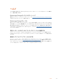
Blackmagic Fairlight Console Kullanım kılavuzu
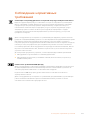
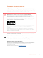
- Tip
- Kullanım kılavuzu


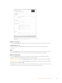
Welcome
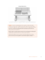
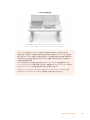
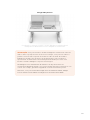
Thank you for purchasing a Blackmagic Fairlight console for your audio post production!
Fairlight has been the premiere audio post production suite in the film and television industries
for decades. It has a long history of innovative software and hardware engineering that’s led the
way for music and audio production. We are excited about the new Fairlight console and believe
you will enjoy your experience with it.
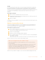
Your Fairlight console is customizable, letting you install just the Fairlight modules you want
depending on the number of bays in your console. Modules include the Fairlight Console
Channel Control, Fairlight Console Channel Fader, Fairlight Console Audio Editor and Fairlight
Console LCD Monitor. You can install the modules and build your system to suit your own needs.
All the fine controls in each module are designed for precision handling and finesse, featuring
illuminated buttons with easy to read LCDs that let you monitor your settings and know exactly
what is happening at all times. The faders are also servo assisted, so they are able to be saved
and recalled while maintaining sync with DaVinci Resolve. There is nothing like watching the
faders reacting to your adjustments in realtime while monitoring your audio mix!
With your Fairlight console and DaVinci Resolve’s Fairlight page, you have the tools you need to
shape your audio just the way you want it.
This instruction manual will guide you through assembling your Fairlight console, installing the
Fairlight console modules and getting started with DaVinci Resolve so you can quickly start using
your Fairlight console.
Also, please check the support page on our website at www.blackmagicdesign.com for the
latest version of this manual and for updates to DaVinci Resolve. Keeping your software up to
date will ensure you get all the latest features! We are continually working on new features and
improvements, so we would love to hear from you!
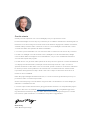
Grant Petty
CEO Blackmagic Design
English

Contents
Fairlight Console Assembly
Fairlight Console Assembly 4
Fairlight Console Components 5
Unpacking and Assembling 7
Tools Required 8
Attaching the Legs to the Console Chassis 8
Alternative Assembly with Two or More People 11
Installing the Fairlight Panels 12
Attaching the Monitor Infill Module 15
Powering the Modules 16
Connecting the Fairlight Modules 17
Configuring the Fairlight Modules 18
Fairlight Panel Setup 19
Changing Network Settings 21
Fairlight Studio Utility 22
Selecting your Fairlight Console in DaVinci Resolve 24
Technical Specifications 25
Fairlight Road Case Dimensions 25
Fairlight Console Dimensions and Weight 25
Fairlight Panels Dimensions and Weight 26
Power Consumption 26
Operating Temperature 26
Help 27
Regulatory Notices 28
Safety Information 29
Warranty 30

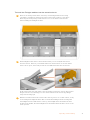
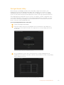
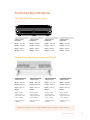
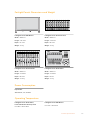
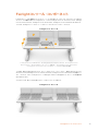
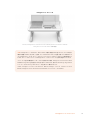
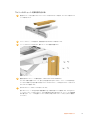
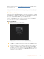
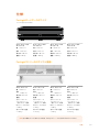
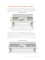
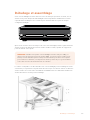
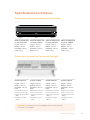
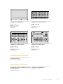
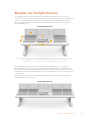
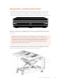
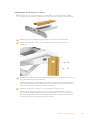
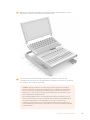
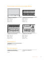
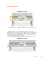
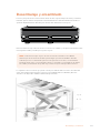
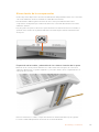
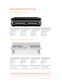
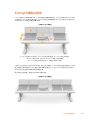
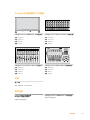
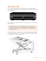
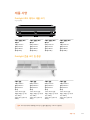
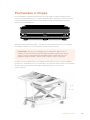
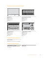
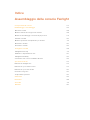
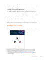
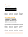
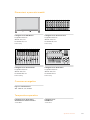
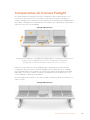
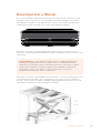
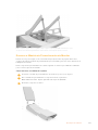
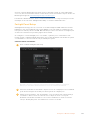
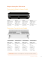
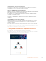
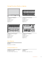
Fairlight Console Components
The Fairlight console is available in 4 configurations that let you build your console to suit
yourproduction requirements. Fairlight modules, for example the Fairlight Console Channel
Control, Fairlight Console Channel Fader, Fairlight Console Audio Editor, and the Fairlight
Console LCD Monitor, are installed into the module slots within the Fairlightconsole chassis.
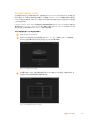
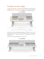
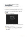
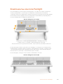
Fairlight 3 Bay Console
The illustration above shows a fully assembled Fairlight 3 Bay console. In a typical 3 bay
configuration, the Fairlight Console Channel Control and Fairlight Console Channel Fader
modules are installed on each side of the Fairlight Console Audio Editor. However you can
place modules in any position you prefer, as your Fairlight console is fully customizable.
On a 4 and 5 bay configuration, additional modules can be installed on each side.
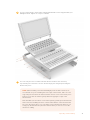
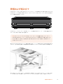
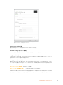
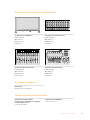
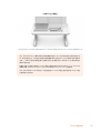
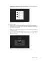
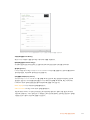
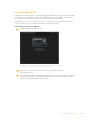
Fairlight 5 Bay Console
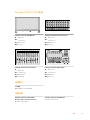
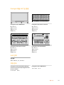
5
4
1
7
6
2
3
1. Fairlight Console LCD Monitor 2. Fairlight Console Channel Control 3. Fairlight Console Channel Fader
4. Fairlight Console chassis, includes legs 5.Fairlight Console Audio Editor
6. Fairlight Console Channel Control Blank 7. Space for your mouse or notes
5Fairlight Console Components

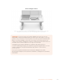
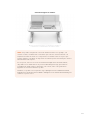
Fairlight 2 Bay Console
The 2 bay configuration sets the Fairlight Console Channel Control module and Fairlight
Console Channel Fader module next to the Fairlight Console Audio Editor
NOTE You can arrange the Fairlight modules on either side of the audio editor and
change the position of the mouse area. For example you may be left handed and want
to have the mouse on the left side of the audio editor module. Fairlight modules are
mounted in a module bracket that can be lifted out and repositioned. Keep reading
thismanual for more information on how to install the Fairlight modules into the
modulebrackets.
A Fairlight Console Channel Rack Kit is also available from Blackmagic Design resellers
if you need to install additional devices in your console. For example Blackmagic
HyperDeck recorders or SmartScope Duo monitors.
Additionally, you can install Fairlight Console LCD Monitor Blank, Fairlight Console
Channel Control Blank, or Fairlight Console Channel Fader Blank kits.
6Fairlight Console Components

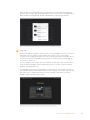
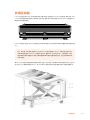
Unpacking and Assembling
Your Fairlight console is shipped in a large, strong and secure road case containing the
Fairlightconsole chassis and legs. Each Fairlight module is shipped separately. Refer to the
‘technical specifications’ section of this manual for a complete list of size and weight
measurements foreach Fairlight configuration.
After opening your Fairlight console's road case, carefully remove the console chassis and
place it gently onto a solid, stable surface strong enough to support the weight of the
chassis and legs.
NOTE Please note that an empty Fairlight 3 bay console weighs 110kg and up to 150kg
for a 5 bay console. The console is built strong and is clearly too heavy to be
unpacked by one person. You will need to make sure that all lifting is performed by
4people using the correct lifting techniques, such as bending your knees, keeping a
straight back and lifting with careful, controlled movements.
The surface your Fairlight console will be placed onto for assembly needs to be high enough
from the ground to ensure the legs are elevated when attaching to the chassis. Allow for at
least550mm. A scissor lift trolley or similar utility is the perfect solution for assembly.
7Unpacking and Assembling

Alternatively, if assembling the console with two or more people, you can stand the chassis on
its rear panel while attaching the legs and feet. Refer to the next section named 'Alternative
Assembly with Two or More People' for more details.
Tools Required
For assembly you will need the following tools:
1 x Torque wrench with
18 mm socket capable of 35 Nm.
1 x Pozidriv 2 torque driver capable
of 0.45 Nm for M3 and M4 screws.
We recommend using torque tools for tightening only, and using a regular wrench or driver
forremoving the screws.
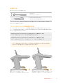
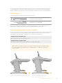
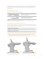
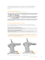
Attaching the Legs to the Console Chassis
The road case contains two legs that attach to each side of the console chassis. When
purchasing a Fairlight console, you can choose from two separate leg designs.
Fairlight Console Leg Kit 0 degrees
This option places the console's surface level to the ground.
Fairlight Console Leg Kit 8 degrees
This option places the console at an 8 degree angle so the console leans toward the operator.
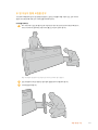
Before attaching the legs to the chassis, you should first secure the feet to each leg.
Each assembled leg weighs 8 to 10 kilograms, so please take care when lifting.
The feet are attached to the console chassis
with their length longer at one end. Ensure the
longer end is facing the front of the console.
When the 8 degrees leg kit is attached,
your Fairlight console will be slightly
higher and tilted towards you.
8Unpacking and Assembling

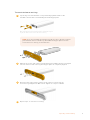
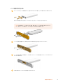
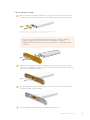
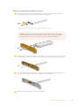
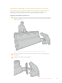
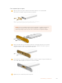
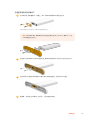
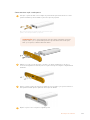
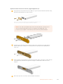
To attach the foot to each leg:
1 Lay the leg on its side with the cover panel facing upwards. Remove the
two M12 screws fromthe end including the small support plate.
After removing the support plate from the standard 0 degrees
leg kit, it is then used to secure the foot to the leg
NOTE If you are attaching the 8 degrees leg kit, be sure to keep the support
plate between the foot and the leg. An additional support plate is used to
secure the foot to the leg, as shown below.
2 Align the foot to the end of the leg and hold it in place. Make sure the rectangular
cutouts on the bottom of the leg and support plate are completely aligned.
3 Now place the support plate on the bottom of the foot and secure the
foot to the leg using the two M12 screws. Tighten to atorque of 35 Nm.
4 Repeat steps 1 to 3 for the second leg.
9Unpacking and Assembling

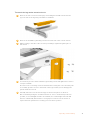
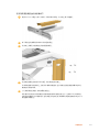
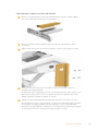
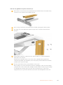
To attach the legs to the console chassis:
1 Remove the side cover from each leg by unscrewing the four M3 screws from the
opposite side of the leg using a Pozidriv 2 screwdriver.
2 Remove the four M12 leg fastening screws from each side of the console chassis.
3 Align each leg to the side of the console by mounting it against the guide pins on
the chassis.
4 Secure the legs to the chassis with the leg fastening screws and tighten the screws to
atorque of 35 Nm.
The side cover for each leg can be reattached later. Leaving the cover off at this point
of assembly provides access to the inside of the leg for when you are wiring up the
panels inside the console.
5 Carefully lower the console from the support surface and place it on the floor.
Werecommend placing the assembled chassis as close to its intended position as
possible, as once Fairlight modules are installed, the overall weight of the unit will
increase substantially. Ensure there is enough space at the rear of the chassis to
replace the back panel before securing your console into position.
10Unpacking and Assembling

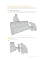
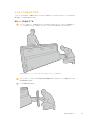
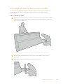
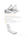
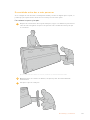
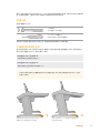
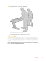
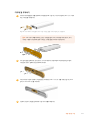
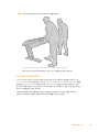
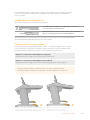
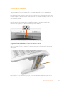
Alternative Assembly with Two or More People
If you don't have access to a scissor lift trolley or similar utility and have someone tohelp you,
you can stand the chassis on its rear panel and attach the legs and feet from this position.
To assemble the legs and feet:
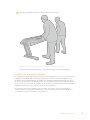
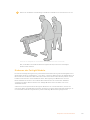
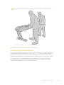
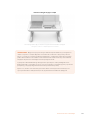
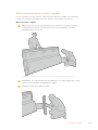
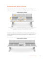
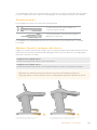
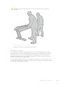
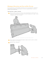
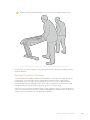
1 After removing the console chassis from its road case, gently lean the chassis onto its
rear panel. Ensure a second person holds the chassis in place so it does not slip.
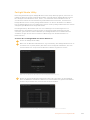
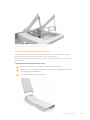
Lean the console chassis onto its rear panel so the front is facing upwards
2 With the console chassis securely held in place, attach the legs as shown in the
previous section.
3 Attach the feet to each leg.
11Unpacking and Assembling

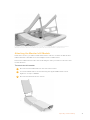
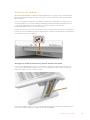
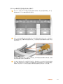
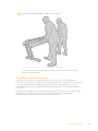
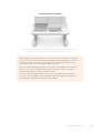
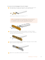
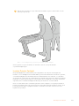
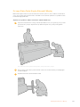
4 Once the legs and feet are attached, lean the chassis onto its feet into its
standing position.
Lean the Fairlight console onto its feet, ready to install the Fairlight panels
With the legs and feet attached to the console chassis, you can now install the Fairlight panels.
Installing the Fairlight Panels
The most common layout Fairlight audio engineers use for mounting the modules is to place
the Fairlight Console Audio Editor directly in front of the operator, the Fairlight Console Channel
Control and Channel Fader modules on each side, and the channel control modules above
each channel fader module. Their respective LCD monitors are installed along the top with the
monitor infill module. The small surface in between the Fairlight modules is for a mouse
or trackball.
If you don't have all the modules for a full console, you can fill in the spaces with blank panels
until you are ready to add more modules later. You can add modules any time you like and as
you need them based on your production requirements.
12Unpacking and Assembling

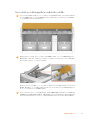
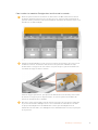
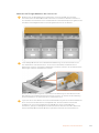
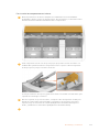
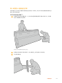
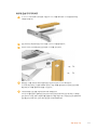
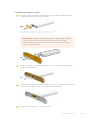
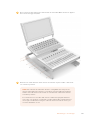
To install the Fairlight modules into the console chassis:
1 Remove the back panel from the chassis by unscrewing the M3 screws using
a Pozidriv 2 screwdriver, and keep the panel and screws nearby in a safe place.
Removing the back panel provides better access to the inside of the chassis
when installing the Fairlight modules.
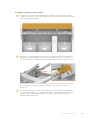
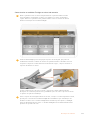
2 Each Fairlight module has its own module bracket you can easily lift and remove
from the chassis. This lets you install modules into their brackets on a bench where
there is more space, then easily mount the assembled brackets into the chassis.
Hold each bracket arm and gently rotate the bracket up from the chassis. The bracket
hinges from the rear, allowing you to free the bracket from the chassis by pulling it
away from the hinge pin.
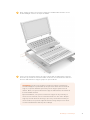
3 With the module bracket removed from the chassis, place it on a stable surface, ready
forattaching the Fairlight modules. We recommend installing modules starting with
the Fairlight Console LCD monitor at the top, the Fairlight Console Channel Control
module in the middle, then the Fairlight Console Channel Fader module closest to the
audio operator.
13Unpacking and Assembling

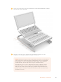
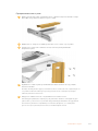
4 Secure each module to the bracket usingthe M4 Pozidriv screws supplied with your
Fairlight module. Tighten to a torque of 1.5 Nm.
5 You can now place the assembled module bracket back into the chassis by
repositioning its rear latchesover the chassis hinge pins and gently lowering the
bracket into place.
NOTE When installing a bracket with Fairlight panel modules attached, we
recommend one person holding thefront edge of the bracket, with a second
supporting the bracket from underneath the chassis as it is lowered into place.
This lets you lower the bracket gently without dropping the edge at the
finalmoment.
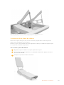
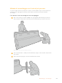
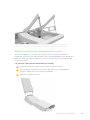
After installation, the brackets can be lifted again by pushing from underneath
with one hand, and lifting the front of the bracket with the other. Each bracket
has a bay lift support brace you can swing out from underneath. This lets you
safely prop the bracket away from the chassis when you need to access the
interior for cabling.
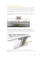
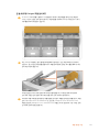
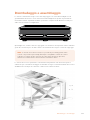
14Unpacking and Assembling

Lower the support brace by holding the brace handles and rotating the brace down from the bracket.
Allow the feet of the brace to rest inside and against the front of the chassis so it cannot move.
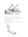
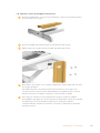
Attaching the Monitor Infill Module
Inside the road case, you’ll find a small cardboard box. This box contains the LCD monitor
infill module that is installed next to the Fairlight console's LCD monitors.
Remove the infill bracket from the chassis following the same procedure used for the other
module brackets.
To attach the infill module:
1 Place the monitor infill module into the neck of the bracket.
2 Secure the infill module to the bracket using the supplied M4 Pozidriv screws.
Tighten to a torque of 0.45Nm.
3 Place the bracket back into the chassis.
15Unpacking and Assembling

Powering the Modules
Each Fairlight module is powered independently via its own power input. Simply plug each
module into your mains power supply using a standard IEC power cable.
We recommend using five way power boards to distribute power to the Fairlight modules, with
each power board to supply up to five modules only. Ensure the power boards are not daisy
chained and are each independently connected to mains power.
Two chassis earth points are built into the inner sides of the chassis for securing to a
building earth point. Refer to the safety information page near the end of this manual for
further information.
Connect power to each Fairlight module via its standard IEC power input
Arranging Cables and Replacing the Leg Side Covers
Your Fairlight console is designed to keep cables tidy. After connecting power cables, you can
bundle them together and guide them through the cable slots on each leg.
Once cables are in place, you can then re-install the leg side covers and tightentheir
4 x M3 Pozidriv screws to a torque of 0.35Nm.
16Unpacking and Assembling

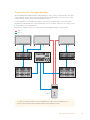
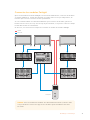
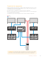
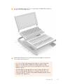
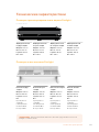
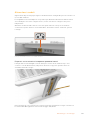
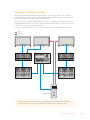
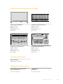
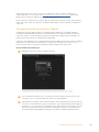
Connecting the Fairlight Modules
After installing the Fairlight modules and plugging in power, connect each module to the other
using an Ethernet daisy chain. It doesn’t matter which particular unit is connected to the other,
as long asthey are all connected via their Ethernet ports.
If you would like to use an Ethernet switch to connect the modules, this is ok and just place
the Ethernet switch inside the console where there is lots of space. Then you can connect each
panel module to the switch directly.
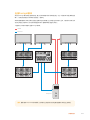
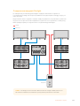
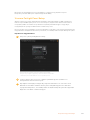
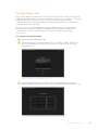
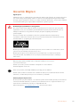
Below is an example of how you could connect the Fairlight modules in a daisy chain.
Ethernet
HDMI
Computer
CONTROL ROOM STUDIO
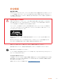
TIP We recommend using 1.2 meter Cat6 Ethernet cables. These will allow you to
liftthe panel brackets after installation without stretching the cables.
17Unpacking and Assembling

Connecting the Fairlight Console to your Computer
Once all the modules in the console are connected together via ethernet,
connect one of them to the computer that will run DaVinci Resolve.
Connecting the Computer’s HDMI or SDI Output
The LCD monitor above the Fairlight Audio Editor connects to your computer’s HDMI monitor
output. This lets you monitor DaVinci Resolve’s Fairlight page.
This LCD monitor can also be connected to the SDI output from video playback equipment,
for example a Videohub router or Decklink video output.
You can also bundle the Ethernet and video cables together with the power cables that are
threaded through your console’s legs and feet. This keeps all cables neatly together to and
from your Fairlight console.
Reattaching the Chassis Back Panel
Now that all your Fairlight modules are installed, powered and connected, the final step to
complete the assembly of your console is to reattach the chassis’ back panel.
Secure in place using the M3 Pozidriv screws and tighten to a torque of 0.45 Nm.
This completes the assembly and connection setup for your Fairlight console. You are now
ready to confirm your console is working with DaVinci Resolve.
Configuring the Fairlight Modules
The next step is to configure your Fairlight console for your studio.
There are two Fairlight utilities that are included in the DaVinci Resolve installer. The utilities
arecalled Fairlight Panel Setup and Fairlight Studio Utility.
18Configuring the Fairlight Modules

The full studio version of DaVinci Resolve can be installed from the SD card included
withyourFairlight Console, but we recommend downloading the latest version from the
Blackmagic Design Support Center at www.blackmagicdesign.com/support.
To install DaVinci Resolve, launch the DaVinci Resolve installer and follow the onscreen
prompts. Be sure to select the 'Fairlight Studio Utility' when installing DaVinci Resolve.
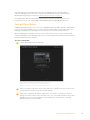
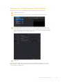
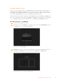
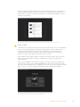
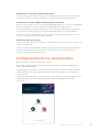
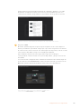
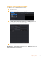
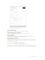
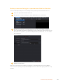
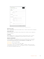
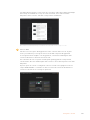
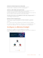
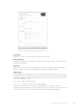
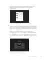
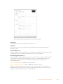
Fairlight Panel Setup
Fairlight Panel Setup can be connected to the Fairlight module via USB or Ethernet using DHCP.
If you are not using a DHCP server, you can set the network settings to a fixed IP address via
USB. More information for changing network settings is provided later in this manual.
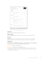
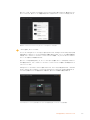
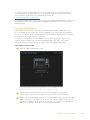
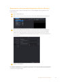
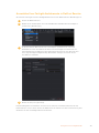
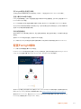
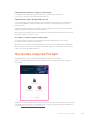
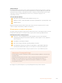
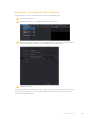
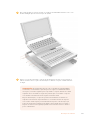
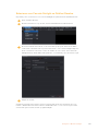
When configuring the Fairlight console for your studio, the first step is to name each module
using the Fairlight Panel Setup utility. This lets you easily identify each panel module by clicking
on the 'identify this panel' checkbox.
To name each module:
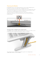
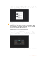
1 Launch the Fairlight Panel Setup utility.
The currently selected module will be visible on the setup
utility home screen. Navigate to each installed unit by
clicking on the arrows on each side of the home screen
2 Select a module on the home screen and click on the settings icon. You can also click
on the module's image to open the settings window.
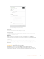
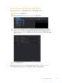
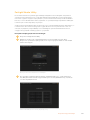
3 Click on the 'configure' tab. Under 'panel name' you will see a 'set label to' text box.
Changethe name in the text box and click 'save'. You can visually identify each module
installed in your console by clicking on the 'identify this panel' checkbox. This will
illuminate features on the module.
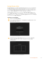
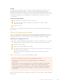
19Configuring the Fairlight Modules

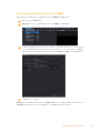
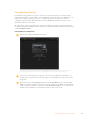
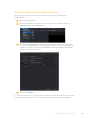
Assign a custom name for each Fairlight module using the
'configure' settings in the Fairlight Panel Setup utility
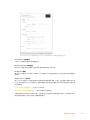
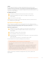
Studio Name
Name the studio this Fairlight module will be assigned to.
Network Settings
Refer to the ‘Changing Network Settings’ section for information on manually changing
these settings.
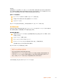
Brightness
Changes the brightness of the Fairlight module’s LCDs, or the brightness of the Fairlight
Console LCD Monitor. Drag the slider left or right to decrease or increase the brightness.
Display Source
Each Fairlight Console LCD Monitor can be set as a data display or video monitor. This means
the monitor can be set to display the Fairlight page connected via Ethernet, or a video image if
there is a signal connected to the monitor's HDMI or SDI video input.
Data display – Displays the Fairlight page.
Video monitor – Displays the SDI or HDMI video input.
If a video signal is connected to either the HDMI or SDI input, the monitor will automatically
detect which input is being used. However, if both inputs have a video signal connected, you
can manually set the desired input.
20Configuring the Fairlight Modules
Sayfa yükleniyor...
Sayfa yükleniyor...
Sayfa yükleniyor...
Sayfa yükleniyor...
Sayfa yükleniyor...
Sayfa yükleniyor...
Sayfa yükleniyor...
Sayfa yükleniyor...
Sayfa yükleniyor...
Sayfa yükleniyor...
Sayfa yükleniyor...
Sayfa yükleniyor...
Sayfa yükleniyor...
Sayfa yükleniyor...
Sayfa yükleniyor...
Sayfa yükleniyor...
Sayfa yükleniyor...
Sayfa yükleniyor...
Sayfa yükleniyor...
Sayfa yükleniyor...
Sayfa yükleniyor...
Sayfa yükleniyor...
Sayfa yükleniyor...
Sayfa yükleniyor...
Sayfa yükleniyor...
Sayfa yükleniyor...
Sayfa yükleniyor...
Sayfa yükleniyor...
Sayfa yükleniyor...
Sayfa yükleniyor...
Sayfa yükleniyor...
Sayfa yükleniyor...
Sayfa yükleniyor...
Sayfa yükleniyor...
Sayfa yükleniyor...
Sayfa yükleniyor...
Sayfa yükleniyor...
Sayfa yükleniyor...
Sayfa yükleniyor...
Sayfa yükleniyor...
Sayfa yükleniyor...
Sayfa yükleniyor...
Sayfa yükleniyor...
Sayfa yükleniyor...
Sayfa yükleniyor...
Sayfa yükleniyor...
Sayfa yükleniyor...
Sayfa yükleniyor...
Sayfa yükleniyor...
Sayfa yükleniyor...
Sayfa yükleniyor...
Sayfa yükleniyor...
Sayfa yükleniyor...
Sayfa yükleniyor...
Sayfa yükleniyor...
Sayfa yükleniyor...
Sayfa yükleniyor...
Sayfa yükleniyor...
Sayfa yükleniyor...
Sayfa yükleniyor...
Sayfa yükleniyor...
Sayfa yükleniyor...
Sayfa yükleniyor...
Sayfa yükleniyor...
Sayfa yükleniyor...
Sayfa yükleniyor...
Sayfa yükleniyor...
Sayfa yükleniyor...
Sayfa yükleniyor...
Sayfa yükleniyor...
Sayfa yükleniyor...
Sayfa yükleniyor...
Sayfa yükleniyor...
Sayfa yükleniyor...
Sayfa yükleniyor...
Sayfa yükleniyor...
Sayfa yükleniyor...
Sayfa yükleniyor...
Sayfa yükleniyor...
Sayfa yükleniyor...
Sayfa yükleniyor...
Sayfa yükleniyor...
Sayfa yükleniyor...
Sayfa yükleniyor...
Sayfa yükleniyor...
Sayfa yükleniyor...
Sayfa yükleniyor...
Sayfa yükleniyor...
Sayfa yükleniyor...
Sayfa yükleniyor...
Sayfa yükleniyor...
Sayfa yükleniyor...
Sayfa yükleniyor...
Sayfa yükleniyor...
Sayfa yükleniyor...
Sayfa yükleniyor...
Sayfa yükleniyor...
Sayfa yükleniyor...
Sayfa yükleniyor...
Sayfa yükleniyor...
Sayfa yükleniyor...
Sayfa yükleniyor...
Sayfa yükleniyor...
Sayfa yükleniyor...
Sayfa yükleniyor...
Sayfa yükleniyor...
Sayfa yükleniyor...
Sayfa yükleniyor...
Sayfa yükleniyor...
Sayfa yükleniyor...
Sayfa yükleniyor...
Sayfa yükleniyor...
Sayfa yükleniyor...
Sayfa yükleniyor...
Sayfa yükleniyor...
Sayfa yükleniyor...
Sayfa yükleniyor...
Sayfa yükleniyor...
Sayfa yükleniyor...
Sayfa yükleniyor...
Sayfa yükleniyor...
Sayfa yükleniyor...
Sayfa yükleniyor...
Sayfa yükleniyor...
Sayfa yükleniyor...
Sayfa yükleniyor...
Sayfa yükleniyor...
Sayfa yükleniyor...
Sayfa yükleniyor...
Sayfa yükleniyor...
Sayfa yükleniyor...
Sayfa yükleniyor...
Sayfa yükleniyor...
Sayfa yükleniyor...
Sayfa yükleniyor...
Sayfa yükleniyor...
Sayfa yükleniyor...
Sayfa yükleniyor...
Sayfa yükleniyor...
Sayfa yükleniyor...
Sayfa yükleniyor...
Sayfa yükleniyor...
Sayfa yükleniyor...
Sayfa yükleniyor...
Sayfa yükleniyor...
Sayfa yükleniyor...
Sayfa yükleniyor...
Sayfa yükleniyor...
Sayfa yükleniyor...
Sayfa yükleniyor...
Sayfa yükleniyor...
Sayfa yükleniyor...
Sayfa yükleniyor...
Sayfa yükleniyor...
Sayfa yükleniyor...
Sayfa yükleniyor...
Sayfa yükleniyor...
Sayfa yükleniyor...
Sayfa yükleniyor...
Sayfa yükleniyor...
Sayfa yükleniyor...
Sayfa yükleniyor...
Sayfa yükleniyor...
Sayfa yükleniyor...
Sayfa yükleniyor...
Sayfa yükleniyor...
Sayfa yükleniyor...
Sayfa yükleniyor...
Sayfa yükleniyor...
Sayfa yükleniyor...
Sayfa yükleniyor...
Sayfa yükleniyor...
Sayfa yükleniyor...
Sayfa yükleniyor...
Sayfa yükleniyor...
Sayfa yükleniyor...
Sayfa yükleniyor...
Sayfa yükleniyor...
Sayfa yükleniyor...
Sayfa yükleniyor...
Sayfa yükleniyor...
Sayfa yükleniyor...
Sayfa yükleniyor...
Sayfa yükleniyor...
Sayfa yükleniyor...
Sayfa yükleniyor...
Sayfa yükleniyor...
Sayfa yükleniyor...
Sayfa yükleniyor...
Sayfa yükleniyor...
Sayfa yükleniyor...
Sayfa yükleniyor...
Sayfa yükleniyor...
Sayfa yükleniyor...
Sayfa yükleniyor...
Sayfa yükleniyor...
Sayfa yükleniyor...
Sayfa yükleniyor...
Sayfa yükleniyor...
Sayfa yükleniyor...
Sayfa yükleniyor...
Sayfa yükleniyor...
Sayfa yükleniyor...
Sayfa yükleniyor...
Sayfa yükleniyor...
Sayfa yükleniyor...
Sayfa yükleniyor...
Sayfa yükleniyor...
Sayfa yükleniyor...
Sayfa yükleniyor...
Sayfa yükleniyor...
Sayfa yükleniyor...
Sayfa yükleniyor...
Sayfa yükleniyor...
Sayfa yükleniyor...
Sayfa yükleniyor...
Sayfa yükleniyor...
Sayfa yükleniyor...
Sayfa yükleniyor...
Sayfa yükleniyor...
Sayfa yükleniyor...
Sayfa yükleniyor...
Sayfa yükleniyor...
Sayfa yükleniyor...
Sayfa yükleniyor...
Sayfa yükleniyor...
Sayfa yükleniyor...
Sayfa yükleniyor...
Sayfa yükleniyor...
Sayfa yükleniyor...
Sayfa yükleniyor...
Sayfa yükleniyor...
Sayfa yükleniyor...
Sayfa yükleniyor...
Sayfa yükleniyor...
Sayfa yükleniyor...
Sayfa yükleniyor...
Sayfa yükleniyor...
Sayfa yükleniyor...
Sayfa yükleniyor...
Sayfa yükleniyor...
Sayfa yükleniyor...
Sayfa yükleniyor...
Sayfa yükleniyor...
Sayfa yükleniyor...
Sayfa yükleniyor...
Sayfa yükleniyor...
Sayfa yükleniyor...
Sayfa yükleniyor...
Sayfa yükleniyor...
Sayfa yükleniyor...
Sayfa yükleniyor...
Sayfa yükleniyor...
Sayfa yükleniyor...
Sayfa yükleniyor...
Sayfa yükleniyor...
Sayfa yükleniyor...
Sayfa yükleniyor...
Sayfa yükleniyor...
Sayfa yükleniyor...
Sayfa yükleniyor...
Sayfa yükleniyor...
Sayfa yükleniyor...
Sayfa yükleniyor...
Sayfa yükleniyor...
Sayfa yükleniyor...
Sayfa yükleniyor...
Sayfa yükleniyor...
Sayfa yükleniyor...
Sayfa yükleniyor...
Sayfa yükleniyor...
Sayfa yükleniyor...
Sayfa yükleniyor...
Sayfa yükleniyor...
Sayfa yükleniyor...
Sayfa yükleniyor...
Sayfa yükleniyor...
Sayfa yükleniyor...
Sayfa yükleniyor...
Sayfa yükleniyor...
Sayfa yükleniyor...
Sayfa yükleniyor...
Sayfa yükleniyor...
Sayfa yükleniyor...
Sayfa yükleniyor...
Sayfa yükleniyor...
Sayfa yükleniyor...
Sayfa yükleniyor...
Sayfa yükleniyor...
Sayfa yükleniyor...
Sayfa yükleniyor...
Sayfa yükleniyor...
Sayfa yükleniyor...
Sayfa yükleniyor...
Sayfa yükleniyor...
Sayfa yükleniyor...
Sayfa yükleniyor...
Sayfa yükleniyor...
Sayfa yükleniyor...
Sayfa yükleniyor...
-
 1
1
-
 2
2
-
 3
3
-
 4
4
-
 5
5
-
 6
6
-
 7
7
-
 8
8
-
 9
9
-
 10
10
-
 11
11
-
 12
12
-
 13
13
-
 14
14
-
 15
15
-
 16
16
-
 17
17
-
 18
18
-
 19
19
-
 20
20
-
 21
21
-
 22
22
-
 23
23
-
 24
24
-
 25
25
-
 26
26
-
 27
27
-
 28
28
-
 29
29
-
 30
30
-
 31
31
-
 32
32
-
 33
33
-
 34
34
-
 35
35
-
 36
36
-
 37
37
-
 38
38
-
 39
39
-
 40
40
-
 41
41
-
 42
42
-
 43
43
-
 44
44
-
 45
45
-
 46
46
-
 47
47
-
 48
48
-
 49
49
-
 50
50
-
 51
51
-
 52
52
-
 53
53
-
 54
54
-
 55
55
-
 56
56
-
 57
57
-
 58
58
-
 59
59
-
 60
60
-
 61
61
-
 62
62
-
 63
63
-
 64
64
-
 65
65
-
 66
66
-
 67
67
-
 68
68
-
 69
69
-
 70
70
-
 71
71
-
 72
72
-
 73
73
-
 74
74
-
 75
75
-
 76
76
-
 77
77
-
 78
78
-
 79
79
-
 80
80
-
 81
81
-
 82
82
-
 83
83
-
 84
84
-
 85
85
-
 86
86
-
 87
87
-
 88
88
-
 89
89
-
 90
90
-
 91
91
-
 92
92
-
 93
93
-
 94
94
-
 95
95
-
 96
96
-
 97
97
-
 98
98
-
 99
99
-
 100
100
-
 101
101
-
 102
102
-
 103
103
-
 104
104
-
 105
105
-
 106
106
-
 107
107
-
 108
108
-
 109
109
-
 110
110
-
 111
111
-
 112
112
-
 113
113
-
 114
114
-
 115
115
-
 116
116
-
 117
117
-
 118
118
-
 119
119
-
 120
120
-
 121
121
-
 122
122
-
 123
123
-
 124
124
-
 125
125
-
 126
126
-
 127
127
-
 128
128
-
 129
129
-
 130
130
-
 131
131
-
 132
132
-
 133
133
-
 134
134
-
 135
135
-
 136
136
-
 137
137
-
 138
138
-
 139
139
-
 140
140
-
 141
141
-
 142
142
-
 143
143
-
 144
144
-
 145
145
-
 146
146
-
 147
147
-
 148
148
-
 149
149
-
 150
150
-
 151
151
-
 152
152
-
 153
153
-
 154
154
-
 155
155
-
 156
156
-
 157
157
-
 158
158
-
 159
159
-
 160
160
-
 161
161
-
 162
162
-
 163
163
-
 164
164
-
 165
165
-
 166
166
-
 167
167
-
 168
168
-
 169
169
-
 170
170
-
 171
171
-
 172
172
-
 173
173
-
 174
174
-
 175
175
-
 176
176
-
 177
177
-
 178
178
-
 179
179
-
 180
180
-
 181
181
-
 182
182
-
 183
183
-
 184
184
-
 185
185
-
 186
186
-
 187
187
-
 188
188
-
 189
189
-
 190
190
-
 191
191
-
 192
192
-
 193
193
-
 194
194
-
 195
195
-
 196
196
-
 197
197
-
 198
198
-
 199
199
-
 200
200
-
 201
201
-
 202
202
-
 203
203
-
 204
204
-
 205
205
-
 206
206
-
 207
207
-
 208
208
-
 209
209
-
 210
210
-
 211
211
-
 212
212
-
 213
213
-
 214
214
-
 215
215
-
 216
216
-
 217
217
-
 218
218
-
 219
219
-
 220
220
-
 221
221
-
 222
222
-
 223
223
-
 224
224
-
 225
225
-
 226
226
-
 227
227
-
 228
228
-
 229
229
-
 230
230
-
 231
231
-
 232
232
-
 233
233
-
 234
234
-
 235
235
-
 236
236
-
 237
237
-
 238
238
-
 239
239
-
 240
240
-
 241
241
-
 242
242
-
 243
243
-
 244
244
-
 245
245
-
 246
246
-
 247
247
-
 248
248
-
 249
249
-
 250
250
-
 251
251
-
 252
252
-
 253
253
-
 254
254
-
 255
255
-
 256
256
-
 257
257
-
 258
258
-
 259
259
-
 260
260
-
 261
261
-
 262
262
-
 263
263
-
 264
264
-
 265
265
-
 266
266
-
 267
267
-
 268
268
-
 269
269
-
 270
270
-
 271
271
-
 272
272
-
 273
273
-
 274
274
-
 275
275
-
 276
276
-
 277
277
-
 278
278
-
 279
279
-
 280
280
-
 281
281
-
 282
282
-
 283
283
-
 284
284
-
 285
285
-
 286
286
-
 287
287
-
 288
288
-
 289
289
-
 290
290
-
 291
291
-
 292
292
-
 293
293
-
 294
294
-
 295
295
-
 296
296
-
 297
297
-
 298
298
-
 299
299
-
 300
300
-
 301
301
-
 302
302
-
 303
303
-
 304
304
-
 305
305
-
 306
306
-
 307
307
-
 308
308
-
 309
309
-
 310
310
-
 311
311
-
 312
312
-
 313
313
-
 314
314
-
 315
315
-
 316
316
-
 317
317
-
 318
318
-
 319
319
-
 320
320


Blackmagic Fairlight Console Kullanım kılavuzu
- Tip
- Kullanım kılavuzu
diğer dillerde
İlgili makaleler
-
Blackmagic HyperDeck Kullanım kılavuzu
-
-
-
-
-
-
-
-
-
