
Owner’s Manual
AV Receiver English for Europe

En 2
BEFORE USE
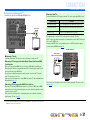
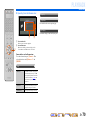
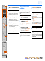
About this manual
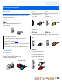
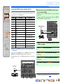
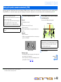
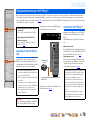
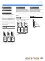
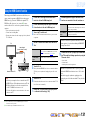
Supplied accessories
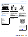
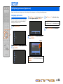
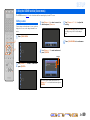
Check that you received all of the following parts.
• Remote control
• Simplified Remote Control
• Batteries (AAA, LR03, UM-4) x 4
• Power cable
• YPAO microphone
• AM loop antenna
• Indoor FM antenna
• Microphone base
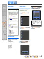
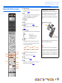
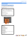
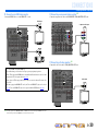
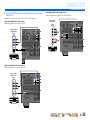
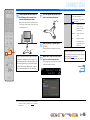
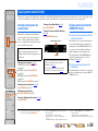
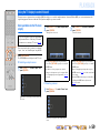
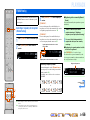
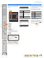
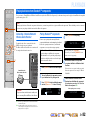
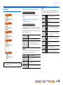
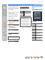
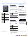
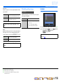
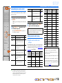
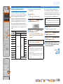
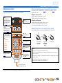
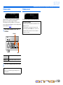
Language selection
This procedure allows you to select the language of
menus and messages on the TV screen.
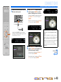
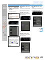
1
Press hON SCREEN to display the ON
SCREEN menu.
2
Press iCursor B / C to select “Setup” and
press iENTER.
3
Press iCursor D / E to select the
“Language” and press iENTER.
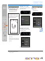
4
Press iCursor B / C to select the favorite
language from the following options.
5
Press hON SCREEN to close the ON
SCREEN menu.
ON SCREEN
ENTER
SOU
R
C
E
R
ECEIVE
R
AV
AU
DI
O
4
3
1
2
7
5
6
V
-A
UX
4
3
1
2
US
B
MU
LTI
N
ET
P
H
O
N
O
TUNER
D
OC
K
[
A
]
[
B
]
h
i
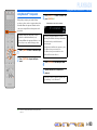
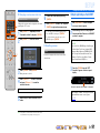
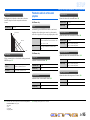
• Some features are not available in certain regions.
• This manual is created prior to production. Design and
specifications are subject to change in part as a result
of improvements, etc. In case of differences between
the manual and product, the product has priority.
• “
hON SCREEN” (example) indicates the name of
the parts on the remote control. Refer to the “Remote
control” (☞
p. 12) for the information about each
position of the parts.
• J
1 indicates that the reference is in the footnote.
Refer to the corresponding numbers on the bottom of
the page.
• ☞
indicates the page describing the related
information.
• Click on the “ ” at the bottom of the page to
display the corresponding page in “Part names and
functions.”
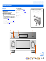
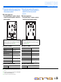
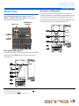
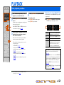
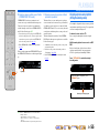
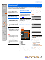
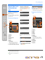
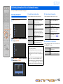
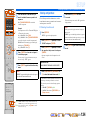
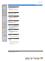
Front panel
Rear panel
Front panel display
Remote control
English (English), (Japanese),
(French), (German), (Spanish),
(Russian)

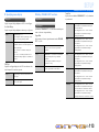
En 3
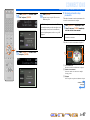
CONTENTS
INTRODUCTION
Features and capabilities...................................................5
Using the TV OSD to operate the unit .............................6
Basic operation of OSD menu..........................................6
Viewing or modifying content
for the current input source <Content window>...............6
Configuring settings for this unit
<ON SCREEN menu>......................................................6
Adjust settings for each input source
<Option menu>.................................................................7
Part names and functions..................................................8
Front panel........................................................................8
Front panel with the cover opened ...................................9
Rear panel.......................................................................10
Front panel display .........................................................11
Remote control ...............................................................12
Remote control with the cover opened...........................13
On-screen display ...........................................................14
CONNECTIONS
Connecting speakers........................................................15
Speaker channels and functions......................................15
Speaker layout ................................................................16
Connecting speakers and subwoofers.............................20
Advanced speaker configuration ....................................23
Speaker layout utilizing an external power amplifier.....23
Connecting an external amplifier ...................................27
Connecting external components....................................28
Jacks and cables..............................................................28
Connecting a TV monitor...............................................29
Connecting BD/DVD players and other devices............32
Connecting game consoles or video camcorders............37
Connecting a multi-format player
or an external decoder ....................................................37
Connecting a SCENE link
playback-compatible device ...........................................38
Using the Trigger function to link
external component power ............................................. 38
Connecting audio/video recording devices .................... 39
Connecting to the network ............................................. 39
Connecting a USB storage device.................................. 40
Connecting the FM/AM antennas.................................. 41
Setting up the speaker parameters automatically
(YPAO).............................................................................. 42
PLAYBACK
Basic playback procedure ............................................... 51
Changing input settings with a single key
(SCENE function)............................................................ 53
Selecting the SCENE suitable
for the external component............................................. 53
Enjoying favorite sound field effect ............................... 54
Selecting sound programs and sound decoders.............. 54
Enjoying surround sound
with the CINEMA DSP function ................................... 54
Enjoying unprocessed playback
(Straight decoding mode)............................................... 55
Enjoying Hi-Fi Sound Quality (Pure Direct Mode) ....... 56
Enjoying stereo playback ............................................... 56
Enjoying compressed music source with better sound
quality (Compressed Music Enhancer) .......................... 56
Sound programs.............................................................. 57
Using the TV display to control this unit....................... 59
Basic operations via the TV screen display ................... 59
Configuring settings specific
to an individual input source (Option menu)................ 61
Option menu display and setup ...................................... 61
Option menu................................................................... 62
Confirming and operating input sources from the
content window ................................................................ 65
Displaying the content window on the TV screen ......... 65
Switching the display between the Now Playing view
and the Browse view ...................................................... 65
FM/AM tuning................................................................. 66
Selecting a frequency for reception (Normal tuning) .... 66
Radio Data System tuning ............................................. 67
Navigating the FM/AM tuner
from the content window ............................................... 69
Playing back tunes on the PC......................................... 71
Windows Media Player setup......................................... 71
Playback of PC music contents...................................... 71
Playing back tunes on the USB storage devices............ 73
Playback of the USB storage device.............................. 73
Listening to the Internet Radio ...................................... 75
Listening to Internet Radio ............................................ 75
Using shortcut function................................................... 77
Playing back tunes from your iPod™/iPhone™........... 78
Connecting the Universal Dock for iPod ....................... 78
Controlling an iPod™/iPhone™.................................... 78
Playing iPod™/iPhone™ from the menu screen
(Menu browse control)................................................... 79
Operating basic playback functions
via the remote control (Simple remote control)............. 80
Playing iPod™/iPhone™ with wireless connection ...... 80
Playing back tunes from Bluetooth™ components ...... 82
Connecting a Yamaha Bluetooth Wireless Audio
Receiver.......................................................................... 82
Pairing Bluetooth™ components................................... 82
Using Bluetooth™ components..................................... 83
Controlling this unit by using the web browser
(Web Control Center)...................................................... 84
Displaying and operating Web Control Center .............. 84

En 4
SETUP
Configuring input sources (Input menu) .......................86
Configuring input sources ..............................................86
Input menu......................................................................87
Editing the SCENE function (Scene menu)...................89
Editing a scene................................................................89
Scene menu.....................................................................90
Simple registering as the SCENE...................................91
Setting sound program parameters
(Sound Program menu)...................................................92
Editing sound programs..................................................92
CINEMA DSP parameters .............................................93
Parameters usable in certain sound programs ................95
Parameters usable in surround decoder..........................96
Setting various functions (Setup menu) .........................97
Operating the Setup menu ..............................................97
Setup menu .....................................................................98
Manages settings for speakers ........................................98
Setting the audio output function of this unit ...............102
Setting this unit’s video output function.......................104
Setting HDMI functions ...............................................106
Adjusting this unit’s network parameters.....................108
Setting this unit’s multi-zone function .........................109
Making the receiver easier to use .................................111
Language ......................................................................114
Confirming information of this unit
(Information menu) .......................................................115
Selecting information ...................................................115
Controlling the remote control to operate various
functions..........................................................................117
Keys connecting external components .........................117
Customizing the remote control ...................................118
Setting remote control codes ........................................118
Programming from other remote controls....................120
Changing source names in the display window............122
Macro programming features .......................................123
Clearing configurations ................................................124
Simplified remote control............................................. 126
Extended functionality that can be configured
as needed (Advanced Setup menu)............................... 127
Displaying/Setting the Advanced Setup menu............. 127
Setting the impedance of speakers ............................... 127
Remote sensor .............................................................. 128
Avoiding crossing remote control signals
when using multiple Yamaha receivers........................ 128
Changing TV format .................................................... 129
Removing HDMI video output up-scaling limits......... 129
Recovery and backup of the system settings................ 129
Initializing various settings for this unit....................... 129
Firmware update........................................................... 130
Firmware version.......................................................... 130
Using the HDMI Control function ............................... 131
Enjoying the contents in another room ....................... 135
Connecting Zone2, Zone3 or Zone4 ............................ 135
Controlling Zone2, Zone3 or Zone4 ............................ 137
Enjoying the music in all rooms................................... 138
APPENDIX
Troubleshooting ............................................................. 139
General ......................................................................... 139
HDMI™ ....................................................................... 141
Tuner (FM/AM) ........................................................... 142
USB and Network ........................................................ 143
iPod™/iPhone™ .......................................................... 144
Bluetooth™ .................................................................. 145
Remote control ............................................................. 145
Glossary .......................................................................... 146
Audio information........................................................ 146
Sound program information ......................................... 147
Video information ........................................................ 148
Compatibility of the input
and output video signals............................................... 148
Information on HDMI™............................................... 149
About trademarks ......................................................... 150
Specifications.................................................................. 151
Index ............................................................................... 153

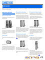
En 5
INTRODUCTION
■ Built-in high-quality, high-power 7-channel amplifier
■ Multi-channel speaker configuration capability
– 2- to 7.1-channel speaker configurations .................................................................................................16
– Presence speaker connections for playback with a richer sound field effect...........................................20
– Bi-amplification connections for high-quality playback .........................................................................21
– External amplifier connections for high-quality playback and expansion of channels ...........................23
– Speaker impedance configuration............................................................................................................21
■ HDMI compatibility
– 8 HDMI input jacks (7 on the rear, 1 on the front) supporting 3D video signal input ............................32
– 2 selectable HDMI output jacks supporting Audio Return Channel and 3D video signal ......................30
■ Automatic setup for speaker acoustic parameters
(YPAO - Yamaha Parametric Room Acoustic Optimizer) ......................................42
■ Extensive inputs (max. 13) for external playback components
– BD/DVD/CD player connection ..............................................................................................................32
– Game console / video camcorder connection ..........................................................................................37
– Multi-format player / external decoder connection .................................................................................37
– iPod/iPhone wired connection .................................................................................................................78
– iPod/iPhone wireless connection .............................................................................................................80
– Bluetooth component connection ............................................................................................................82
■ 1-button input/sound program/setting switching (SCENE function)...................53
■ Built-in sound programs and surround decoders for playback variety of sources
– Spatial sound playback with sound field effects (CINEMA DSP) ..........................................................54
– Playback with no sound field effects (straight decoding) ........................................................................55
– High-fidelity sound playback (Pure Direct).............................................................................................56
– Enhanced sound playback for compressed sources (Compressed Music Enhancer)...............................56
■ Tuner playback
– FM/AM broadcast....................................................................................................................................66
– Radio Data System tuning .......................................................................................................................67
■ Playback and control via network
– Playback of music on the PC and DLNA server......................................................................................71
– Internet radio service playback................................................................................................................75
– Control this unit via network (Web browser control) ..............................................................................84
■ Playback of music on the USB storage devices ................................................... 73
■ Sophisticated on-screen display (OSD) for easy operation
– Selection of input sources, scenes, and sound programs.........................................................................59
– Navigation for the current input source (content window)......................................................................65
– Setup for this unit (ON SCREEN menu).................................................................................................86
– Setup for each input source (Option menu).............................................................................................61
■ Customizable remote control
– Remote control code setup for operation of external components ........................................................117
– Learning function from other remote controls.......................................................................................120
– Programming macro for a series of operations......................................................................................123
■ Multi-room listening capability (Zone2/Zone3/Zone4)........................................ 135
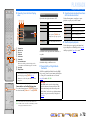
Features and capabilities
Most of functions can be operated with on-screen display on the TV screen. Refer to “Using the TV
OSD to operate the unit” on the following pages for information on functions that can be controlled
using the on-screen display.

INTRODUCTION
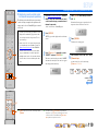
En 6
This unit features a sophisticated on-screen display (OSD) for the TV screen. The OSD is designed to enable visual guidance that simplifies operations. The OSD mainly displays the ON SCREEN and
Option menus, as well as the content window that displays the content of current input sources.
Basic operation of OSD menu
■ Select an input source, scene and sound program
– Select an input source ..............................................................................................................................59
– Select a scene ...........................................................................................................................................59
– Select a sound program............................................................................................................................60
■ Select a language
– Change the language displayed on the TV screen <Language>............................................................114
Viewing or modifying content for the current input source
<Content window>
■ Operate the FM/AM tuner
– Display preset stations for selection ........................................................................................................69
– Display information on the station currently received.............................................................................69
– Perform operations such as searching for and registering stations using the screen button ....................69
■ Operate the Internet radio
– Display information on the station currently received.............................................................................75
– Play back radio contents ..........................................................................................................................75
– Bookmark Internet radio stations.............................................................................................................75
■ Operate the iPod music sources
– Display the list of iPod music sources for selection ................................................................................79
– Perform operations such as play, stop and pause using the TV screen <Menu browse control> ............79
Configuring settings for this unit <ON SCREEN menu>
■ Configure an input source
– Change the input source name <Rename/Icon Select> ...........................................................................87
– Specify a format for digital audio signals <Decoder Mode> ..................................................................88
– Enhance the sound of compressed audio <Enhancer> ............................................................................88
– Output a video signal input from another input source
while playing a multi-channel audio signal <Video Out> .......................................................................88
– Charge the iPod/iPhone when this unit is in standby mode <Standby Charge>......................................88
– Play music sources on a PC using external controls <DMC Control>....................................................88
■ Customize a scene
– Register or clear settings for a selected scene <Save>, <Load>, <Reset> ..............................................90
– Turn on a Yamaha BD/DVD player or CD player connected to this unit automatically
when a scene is selected <SCENE IR> ...................................................................................................90
– Changing a scene name and icon <Rename/Icon Select> .......................................................................91
■ Adjust a sound program (sound program)
– Adjust sound program parameters...........................................................................................................92
■ Display settings information for this unit
– Display audio signal information <Audio Signal>................................................................................115
– Display video signal information <Video Signal> ................................................................................115
– Display HDMI signal information <HDMI Monitor>...........................................................................115
– Display network information <Network>..............................................................................................116
– Display system information <System>..................................................................................................116
– Display Zone information <Zone> ........................................................................................................116
Using the TV OSD to operate the unit
Continues to the
next page

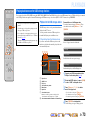
INTRODUCTION
Using the TV OSD to operate the unit
En 7
■ Adjust acoustic parameters to match your speakers and listening environment
– Specify speaker acoustic parameters automatically
(Yamaha Parametric Room Acoustic Optimizer - YPAO).......................................................................42
– Set up this unit’s speaker configuration simply <Power Amp Assign> ..................................................99
– Specify settings for each speaker <Configuration>.................................................................................99
– Control volume control for each speaker <Level> ................................................................................101
– Apply speaker distance settings <Distance> .........................................................................................101
– Control equalizer sound quality <Parametric EQ>................................................................................101
– Adjust test tone speaker <Test Tone> ....................................................................................................102
■ Adjust audio signals output from this unit
– Correct lag between audio and video signals <Lipsync> ......................................................................103
– Select a dynamic range adjustment method <Dynamic Range> ...........................................................103
– Specify the maximum volume <Max Volume>.....................................................................................103
– Specify the initial volume <Initial Volume>..........................................................................................103
– Restrict the video signals during the Pure Direct Mode <Pure Direct Mode> ......................................103
– Adjust DSP effect and volume level <Adaptive DSP Level>................................................................104
■ Adjust video signals output from this unit
– Convert analog video signal to another type of signal <Analog to Analog Conversion> .....................104
– Specify the resolution and aspect ratio of video signals and adjust video quality <Processing>..........104
■ HDMI settings
– Assign the audio input source for the TV <TV Audio Input>...............................................................107
– Listen to TV audio with HDMI cable connection <ARC (Audio Return Channel)>............................106
– Transmit HDMI audio/video to the TV during standby mode <Standby Through> .............................107
– Change the output destination of HDMI input audio signals <Audio Output>.....................................107
■ Network settings
– Specify this unit’s IP address <IP Address>..........................................................................................108
– Accept the commands over a LAN network when this unit is in the standby mode
<Network Standby>...............................................................................................................................108
– Specify the mac address filter for this unit <MAC Address Filter> ......................................................108
■ Enable listening in multiple rooms (multi-zone function)
– Adjust Zone2/Zone3 volume <Zone2 Set/Zone3 Set> ..........................................................................109
– Display the Zone2/Zone3/Zone4 menu on the TV <Monitor Out Assign> ..........................................110
– Rename each zone or scene <Zone2 Scene Rename/Zone3 Scene Rename/
Zone4 Scene Rename/Zone Rename>...................................................................................................111
■ Specify other functions for this unit
– Enter standby mode automatically when no operations are performed <Auto Power Down> .............112
– Assign the other input to the selected input source <Input Assignment> .............................................112
– Adjust the brightness of the front panel display <Dimmer> .................................................................113
– Change the wall paper displayed on the TV screen <Wall Paper>........................................................113
– Specify the function of the TRIGGER OUT jack for controlling external components
<Trigger Output1/Trigger Output2>......................................................................................................113
– Prohibit changes to settings <Memory Guard> .....................................................................................114
Adjust settings for each input source <Option menu>
– Adjust bass and treble levels <Tone Control> .........................................................................................63
– Enable low-volume background music <Adaptive DRC> ......................................................................63
– Enjoying more spatial sound fields <CINEMA DSP 3D Mode>............................................................63
– Adjust the vertical position of dialogues <Dialogue Lift> ......................................................................63
– Select the 5.1-channel signal playback method <Extended Surround> ..................................................63
– Adjust the volume of input sources <Volume Trim>...............................................................................64
– Selecting a video adjustment preset <Video Adjustment> ......................................................................64
– Selecting audio input jacks <Audio Select>............................................................................................64
– Automatically search for and receive a traffic station <Traffic Program> ..............................................64
– Shuffle or repeat the song <Shuffle/Repeat>...........................................................................................64
– Connect / Disconnect Bluetooth component to this unit <Connect/Disconnect> ...................................64
– Pairing Bluetooth component with this unit <Pairing> ...........................................................................64

INTRODUCTION
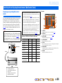
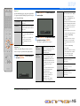
En 8
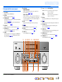
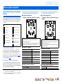
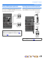
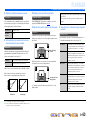
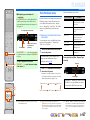
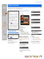
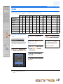
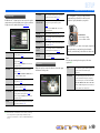
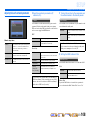
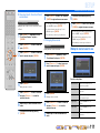
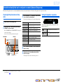
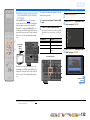
Front panel
a MAIN ZONE A (Power)
Switches this unit between on and standby mode.
b HDMI Through/iPod Charge indicator
Lights up in any of the following cases while the unit is in standby
mode.
• When the Standby Through function is enabled and audio/video
from an external component connected with HDMI is output to a TV
during standby mode (☞
p. 107).
• When an iPod/iPhone, which is placed in the Universal Dock for
iPod, is charging while the unit is in standby mode (☞
p. 88).
This indicator also lights up when the Yamaha Wireless System for
iPod is connected to this unit (☞
p. 80).
c Front panel display
Displays information on this unit (☞
p. 11).
d PURE DIRECT
Switches this unit to Pure Direct Mode (☞
p. 56).
e INPUT selector
Selects an input source from which to playback. Rotate this selector to
cycle through the input sources in order.
f VOLUME
Adjusts the volume level.
Part names and functions
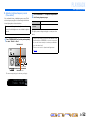
■ Opening and closing the front panel door
To use controls or jacks behind the front panel door, gently press
the bottom of the door to open it. Keep the door closed when not
using controls or jacks behind the front panel door.
Continues to the
next page
a
e f
c db

En 9
INTRODUCTION
Part names and functions
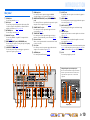
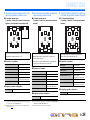
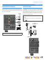
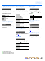
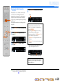
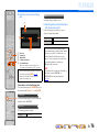
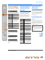
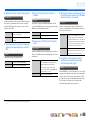
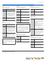
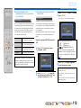
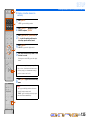
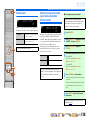
Front panel with the cover opened
g ON SCREEN
Turns on and off the ON SCREEN menu.
h OPTION
Turns on and off the Option menu (☞
p. 61).
i TONE/BALANCE
Adjusts high-frequency/low-frequency output of speakers/headphones
in each zone (☞
p. 52, p. 137).
Adjusts the balance of the volume of the left and right channels in
Zone2, Zone3 or Zone4 (☞
p. 137).
j STRAIGHT
Changes a sound program to straight decoding mode (☞
p. 55).
k PROGRAM l / h
Selects a sound program (☞
p. 54). Press the left or right key
repeatedly to cycle through sound programs.
l SCENE
Switches the input source, the sound program, and the HDMI OUT
with a single button (☞
p. 53, p. 89). When this unit is in standby
mode, press this key to switch on.
m MULTI ZONE
ZONE2/ZONE3/ZONE4
Switches to enable/disable the audio and video output to Zone2,
Zone3 and/or Zone4 (☞
p. 109, p. 135).
ZONE CONTROLS
Switches to Zone2, Zone3 or Zone4 operation mode. This unit, or its
remote control, can be used to select input sources or adjust volume
for an external amplifier in another room or the built-in amplifier for
speakers in another room (☞
p. 137).
n INFO
Changes the information displayed on the front panel display
(☞
p. 11).
o MEMORY
Registers FM/AM stations as preset stations (☞
p. 66). J 1
p FM/AM
Sets the FM/AM tuner band to FM or AM (☞
p. 66). J 1
q PRESET j / i
Selects an FM/AM preset station (☞
p. 67). J1
r Cursor B / C / D / E, ENTER, RETURN
s USB port
For connecting a USB memory device or USB portable audio player
(☞
p. 40).
t DISPLAY
Switches the display between the Now Playing view and the Browse view.
u YPAO MIC jack
Connect the supplied YPAO microphone and adjust the speaker
balance automatically (☞
p. 42).
v PHONES jack
For plugging headphones in. Sound effects applied during playback
can also be heard through the headphones.
w VIDEO AUX jacks
For connecting game consoles to this unit temporarily (☞
p. 37).
x TUNING/CH jj / ii
Changes FM/AM tuner frequencies (☞
p. 66). J 1
Cursor B / C / D / E Select menu items and change settings when
menus, etc., are displayed.
ENTER Confirms a selected item.
RETURN Returns to the previous screen when menus are
displayed, or close the menu.
n
r
xt w
k
mg li o qnjh p
vus
J
1 : Usable when you have selected TUNER input.

En 10
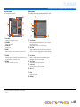
INTRODUCTION
Part names and functions
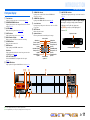
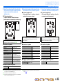
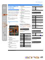
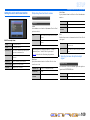
Rear panel
a PHONO jacks
For connecting a turntable (☞
p. 36).
b DOCK jack
For connecting an optional Universal Dock for iPod (such as YDS-
12), Wireless System for iPod (YID-W10), or Bluetooth Wireless
Audio Receiver (YBA-10) (☞
p. 78, p. 80, p. 82).
c NETWORK port
For connecting to a network (☞
p. 39).
d HDMI OUT 1-2 jacks
For connecting an HDMI - compatible TV to output audio/video
signals (☞
p. 30).
e MON.OUT/ZONE OUT jacks (S-VIDEO/VIDEO jacks)
For connecting a TV capable of receiving video input, and outputting
video signals to it (☞
p. 30, p. 31).
f COMPONENT VIDEO jacks
For connecting external components that support component video
output for video signal reception (☞
p. 33).
g HDMI input jacks
For connecting external components equipped with HDMI-
compatible outputs to receive audio/video signals (☞
p. 32).
h MONITOR OUT/ZONE OUT jacks (COMPONENT VIDEO
jacks)
For connecting TV that are compatible with component video signals,
using three cables to output video signal (☞
p. 30).
i REMOTE IN/OUT1-2 jacks
For connecting an external component that supports the remote
control function (☞
p. 38).
j TRIGGER OUT 1-2 jack
For connecting an external component that supports the trigger
function to operate it linked with operation of this unit (☞
p. 38).
k RS-232C terminal
This is a control expansion terminal for custom installation. Consult
your dealer for details.
l AV1-4 jacks
For connecting to external components equipped with audio/video
outputs to receive audio/video signals (☞
p. 33).
m ANTENNA jacks
For connecting AM and FM antennas (☞
p. 41).
n AV OUT jacks
For outputting audio/video signals received when analog inputs are
selected (☞
p. 39).
o AUDIO1-4 jacks
For connecting external components equipped with audio outputs to
receive audio signals (☞
p. 36).
p MULTI CH INPUT jacks
For connecting a player that supports a multi-channel output
(☞
p. 37).
q ZONE OUT jacks
Outputs sound of this unit to an external amplifier set in a different
room. (☞
p. 135).
r PRE OUT terminals
For connecting a subwoofer with built-in amplifier or an external
power amplifier (☞
p. 22, p. 27).
s SPEAKERS terminals
For connecting the front, center, surround and surround back speakers
(☞
p. 20). Connect the front/rear presence speakers (☞p. 20) or the
speakers for Zone2 and Zone3 (☞
p. 21) to the EXTRA SP jacks.
t AC IN
For connecting the supplied power cable.
HDMI OUT
12
MON.OUT/ZONE OUT
MONITOR OUT/ZONE OUT
ZONE OUT PRE OUT
ZONE 2
ZONE 3/ FRONT/
AV OUT
AV OUT/
ZONE 4
YP
B
P
R
SURROUND
SUR. BACK
CENTER
(FRONT)(SINGLE)
1
2
Z
O
NE2
/
Z
O
NE
3/
R
.PRESENC
E
SU
RR
OU
N
D
SU
RR
OU
ND BA
C
K
/
S
PEAKER
S
C
ENTER
AV 1
AV 2
AV
3
AV 4
H
DMI
AV
5
AV 6
AV 7
S
IN
G
LE
FR
O
N
T
BI
-
AMP
EXTRA
S
P
2
4
AV
1
AV
3
AV 4
AV
2
T
ICA
L
OPTICAL
A
UDIO
1
(2 TV)
(3 CD)
AUDI O 2 AUDI O 3
A
UDIO 4
FRON
T
SURROUND
SUR. BAC
K
SUBWOOFE
R
CENTER
MULTI
C
H INPU
T
CO
MP
O
NENT VIDE
O
C
OAXIAL
Ԝ
ԝ
Y
P
B
P
R
Y
P
B
P
R
A
B
C
D
IN
1
2
2
1
OU
T
IN
OU
T
R
EM
O
TE
T
RI
GG
ER
OU
T
+12V 0.1A MAX
(
1 BD/DVD
)
ARC ARC
SELECTABLE
Distinguishing the input and output jacks
The area around the audio/video output jacks is marked
in white to prevent connection errors. Use these jacks to
output audio/video signals to a TV or other external
component.
Output jacks
EXTRA SP1
ZONE2/ZONE3/
R.PRESENCE
ZONE2/ZONE3/
F.PRESENCE
AC IN
SURROUND SURROUND BACK/
SPEAKERS
CENTER
AV 1
HDMI OUT
AV 2 AV 3 AV 4
HDMI
AV 5 AV 6 AV 7
SINGLE
FRONT
BI-AMP
EXTRA SP2
12
PHONO
GND
(1 BD/DVD)
AV 1
DOCK NETWORK
AV 2 AV 3 AV 4
AV 1
AV 3
AV 4
AV 2
COAXIAL COAXIAL
OPTICAL OPTICAL
OPTICAL
AUDI O 1
(2 TV)
(3 CD)
AUDIO 2 AUDIO 3 AUDIO 4
FRONT
SURROUND
SUR. BACK
SUBWOOFER
CENTER
MULTI CH INPUT
COMPONENT VIDEO
COAXIAL
MON.OUT/ZONE OUT
MONITOR OUT/ZONE OUT
ZONE OUT PRE OUT
ZONE 2
ZONE 3/
R. PRESENCE
FRONT/
F. PRESENCE
AV OUT
AV OUT/
ZONE 4
ԘԙԚԛ Ԝԝ
YP
B
P
R
YP
B
P
R
YP
B
P
R
A
B
C
D
SURROUND
SUR. BACK
CENTER
(REAR)
(FRONT)(SINGLE)
SUBWOOFER
1
2
RS-232C
IN
12
2
1
OUT IN OUT
REMOTE
TRIGGER
OUT
+12V 0.1A MAX.
(1 BD/DVD)
ARC ARC
SELECTABLE
ANTENNA
75
GND
AM
FM
(4 RADIO)
bad g kjf
sl nmt
c
e h i
o p q r

En 11
INTRODUCTION
Part names and functions
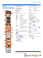
Front panel display
a Tuner indicator
Lights up according to the status of a received station (☞
p. 66).
b ZONE2/ZONE3/ZONE4 indicator
Lights up when the audio or video output to Zone2, Zone3 or Zone4 is
enabled (☞
p. 137).
c SLEEP indicator
Blinks when the sleep timer is on (☞
p. 13, p. 137).
d PARTY indicator
Lights up when the party mode is active (☞
p. 110).
e Multi information display
Displays a range of information on menu items and settings.
f VOLUME indicator
Displays the current volume level.
g HDMI indicator
Lights up during normal HDMI communication.
IN indicator
Lights up when this unit detects the external component connected to
the HDMI input jack (☞
p. 32).
OUT 1/OUT 2 indicators
Indicate which HDMI OUT jack outputs audio/video signals
(☞
p. 30).
h ENHANCER indicator
Lights up when the Compressed Music Enhancer is active (☞
p. 56).
i CINEMA DSP indicator
Lights up when a sound field effect that uses CINEMA DSP
technology is selected.
j CINEMA DSP 3D indicator
Lights up when CINEMA DSP 3D is activated (☞
p. 55).
k Cursor indicators
Light up if corresponding cursors on the remote control are available
for operations.
l MUTE indicator
Blinks when audio is muted.
m Speaker indicators
Indicate speaker terminals from which signals are output.
n ADAPTIVE DRC indicator
Lights when the adaptive dynamic range control feature is tuned on
(☞
p. 63).
Surround L speaker
Subwoofer 1
Surround R speaker
Center speaker
Surround back L
speaker
Surround back R
speaker
Surround back
speaker J1
Front presence L
speaker
Front presence R
speaker
Front L speaker Front R speaker
Subwoofer 2
Rear presence L
speaker
Rear presence R
speaker
■ Switching information on the front panel display
The front panel can display sound programs and surround
decoder names as well as the active input source.
Press uINFO repeatedly to cycle through displayed
informations. J2
VOLUME
AV1
Standard
Input source name
Sound program (DSP program)
STEREO
TUNED
PARTY
ENHANCER
SLEEP
MUTE
VOLUME
ADAPTIVE
DRC
a be fc
ihj mknlgk
d
J
1 : “SB” is displayed when using a 6.1-channel configuration only.
J
2 : During FM/AM reception, the frequency is displayed instead of the input source.

En 12
INTRODUCTION
Part names and functions
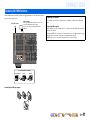
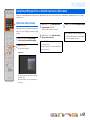
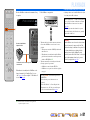
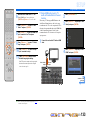
Remote control
a Remote control signal transmitter
Transmits infrared signals.
b SOURCE A (SOURCE Power)
Switches an external component on and off.
c Display window
Displays remote control information.
d Input selector
Select an input source on this unit from which to playback.
e SCENE
Switch the input source and the sound program with a single button
(☞
p. 53). When this unit is in standby mode, press this key to switch
on.
f PROGRAM k / n
Selects a sound program (☞
p. 54). Press the up or down key
repeatedly to cycle through sound programs.
g External component operation keys
Operate recording, playback, and menu displays etc. for external
components (☞
p. 117). J1
h ON SCREEN
Turns on and off the ON SCREEN menu.
i Cursor B / C / D / E, ENTER, RETURN
j PRESET F / G
Selects a preset station when the FM/AM.
k TV control keys
Operate a monitor such as a TV.
l RECEIVER A (RECEIVER Power)
Switches this unit between on and standby mode.
m SOURCE/RECEIVER
Switches remote control key function to operate this unit or an
external component (☞
p. 117). Operate an external component when
this key glows green, or this unit when this key glows orange.
n VOLUME +/-
Adjust the volume level (☞
p. 51).
o MUTE
Turns the mute function of the sound output on and off (☞
p. 51).
p OPTION
Turns on and off the Option menu (☞
p. 61).
q LIGHT
Lights up the silicon buttons while pressing this key.
r DISPLAY
Switches the display between the Now Playing view and the Browse
view.
s Sound selection keys
Switch between the current sound field effect (sound program) and the
surround decoder (☞
p. 54).
LIVE
CLUB
CLASSICAL
PRESET
ENTERTAIN
STEREO
MOVIE
STRAIGHT
2
3
SOURCE
RECEIVER
AV
AUDIO
SCENE
TV
TV VOL TV CH
MUTE
RETURN DISPLAY
TOP MENU
POP-UP/MENU
VOLUME
PROGRAM
1
PURE
DIRECT
MUTE
INPUT
4
4
31
2
75
6
V-AUX
431 2
USB
MULTI
NET
PHONO
TUNER
DOCK
4
REC
ON SCREEN
OPTION
ENTER
[ B ][ A ]
a
c
b
h
i
p
r
q
n
j
k
f
m
o
l
d
e
g
g
s
AV1-7 AV1-7 jacks
V-AUX Front panel VIDEO AUX jacks
AUDIO1-4 AUDIO1-4 jacks
PHONO PHONO jacks
MULTI MULTI CH INPUT jacks
USB A USB storage device connected to the USB port.
NET Internet radio, a USB connected to the USB port,
or a PC connected to the NETWORK port.
DOCK A Universal Dock for iPod, Wireless System for
iPod, or Bluetooth Wireless Audio Receiver
connected to the DOCK jack.
TUNER FM/AM tuner
[A]/[B] Changes the external component to operate with
the gExternal component operation keys
without changing inputs. J1
Cursor B / C / D / E Select menu items and change settings when
menus, etc., are displayed.
ENTER Confirms a selected item.
RETURN Returns to the previous screen when menus are
displayed, or close the menu.
J
1 : You can use gExternal component operation keys for each input source to operate registered components. Remote control codes must be registered for each input
in advance if you want to operate external components (☞
p. 119).

En 13
INTRODUCTION
Part names and functions
Remote control with the cover opened
t Sound selection keys
Switch between the current sound field effect (sound program) and the
surround decoder (☞
p. 54).
u INFO
Cycles the information displayed on the front panel display (the name
of the currently selected input source, the sound program, the
surround decoder, the FM/AM tuner frequency, etc.).
v Numeric keys
Enter numbers.
w PARTY
Switches the party mode on and off (☞
p. 138).
x HDMI OUT
Switches the output jack connected to an HDMI compatible TV
(☞
p. 51).
y Radio control keys
Operates the FM/AM tuner. These keys are used when using the tuner
input.
z SLEEP
Switches this unit to standby mode automatically after a specified
period of time has elapsed (sleep timer). Press this key repeatedly to
set the time for the sleep timer function.
The SLEEP indicator lights up when the sleep timer is on.
A LEVEL
Adjusts the output level for each speaker (☞
p. 101).
B SETUP
Setup this remote control (☞
p. 118).
C ZONE
Switches the zone to be operated by the remote control between the
Main zone, Zone2, Zone3 and Zone4 (☞
p. 137).
2
3
SOURCE
RECEIVER
AV
AUDIO
SCENE
MUTE
RETURN DISPLAY
TOP MENU
POP-UP/MENU
VOLUME
PROGRAM
1
4
4
31
2
75 6
V-AUX
431 2
USB
MULTI
NET
PHONO
TUNER
DOCK
4
ON SCREEN
OPTION
ENTER
FM
MEMORY
AM
INFO
3
TUN./CH
21
6
9
8
SLEEP
7
ENT
0
LEVEL
10
PARTY
ENHANCER
HDMI OUT
SUR.
DECODE
ZONE
SETUP
4
5
[ B ]
[ A ]
u
v
t
y
z
x
A
B
C
w
MEMORY Presets radio stations.
FM Sets the FM/AM tuner band to FM.
AM Sets the FM/AM tuner band to AM.
TUN./CH H / I Changes tuning frequencies.
120min. 90min.
60min.30min.Off
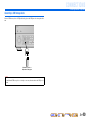
■ Installing batteries in the remote control
When inserting batteries in the remote control, remove the
battery compartment cover from the reverse side of the remote
control, and insert four AAA batteries into the battery
compartment so that they match with the polarity markings (+
and -).
Replace the batteries with new ones if the remote control can
only be operated within a narrow range.
NOTE
If there are remote control codes for external components
registered to the remote control, removing the batteries for more
than 2 minutes, or leaving exhausted batteries in the remote
control, may clear the remote control codes. If this should occur,
replace the batteries with new ones, and set the remote control
codes.
b
a
c
Battery compartment
cover
Battery compartment

INTRODUCTION
Part names and functions
En 14
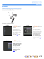
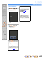
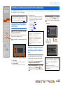
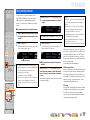
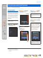
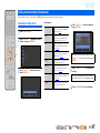
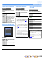
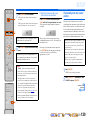
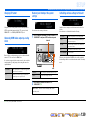
On-screen display
When a TV is connected to this unit, the supplied remote control can be used to specify and verify this
unit’s settings via menus and options displayed on the TV screen.
The following displays are available in the on-screen display.
ON SCREEN menu
Press hON SCREEN to display the ON
SCREEN menu.
Detailed settings for this unit can be
configured. Use this menu to select desired
settings, change their values, or check the
current status of this unit.
Refer to “SETUP” (☞
p. 86) for details.
Option menu
Press pOPTION to display the Option menu.
Configure the optional settings for each input
source. Settings such as “Tone Control” and
“Volume Trim” are applied to this unit
regardless of the input source.
Refer to “Configuring settings specific to an
individual input source (Option menu)”
(☞
p. 61) for details.
Content window
Press dInput selector to display the content
window.
Includes the Browse view and the Now
Playing view. The Now Playing view displays
the status of the source from which music is
currently played back. Adjust settings for
music content from the Browse view.
Refer to “Confirming and operating input
sources from the content window” (☞
p. 65)
for details.

En 15
CONNECTIONS
This unit uses acoustic field effects and sound decoders to bring you the impact of a real movie theater or concert hall. These effects will be brought to you with ideal speaker positioning and
connections in your listening environment.
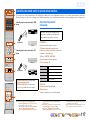
Speaker channels and functions
■
Front left and right speakers
The front speakers are used for the front channel sounds (stereo
sound) and effect sounds.
Front speaker layout:
Place these speakers at an equal distance from the ideal listening
position in the front of the room. When using a projector screen,
the appropriate top positions of the speakers are about 1/4 of the
screen from the bottom.
■
Center speaker
The center speaker is for the center channel sounds (dialog, vocals,
etc.).
Center speaker layout:
Place it halfway between the left and right front speakers. When
using a TV, place the speaker just above or just under the center of
the TV with the front surfaces of the TV and the speaker aligned.
When using a screen, place it just under the center of the screen.
■
Surround left and right speakers
The surround speakers are for effect and vocal sounds while
playing back more than 5.1-channel source. When used with no
surround back speaker while playing back more than 6.1-channel
source (including surround back channel), sound of surround back
channel is distributed between the left and right surround speakers.
Surround speaker layout:
Place the speakers at the rear of the room on the left and right sides
facing the listening position. They should be placed between 60
degrees and 80 degrees from the listening position and with the
speaker tops at a height of 1.5 – 1.8 m from the floor.
■
Presence left and right speakers
The front and rear presence speakers are used for front and rear
effect sounds. When used in combination with the sound programs
(☞
p. 57), a sound with a richer and more spatial presence is
possible.
Presence speaker layout:
Place the left and right front presence speakers 0.5 – 1 m to the
outside of the left and right front speakers respectively. The tops of
the both front and rear presence speakers should be 1.8 m above
the floor.
■
Surround back left and right speakers
The surround back speakers are for rear effect sounds while
playing back more than 6.1-channel source. When used with only
one surround back speaker while playing back more than 7.1-
channel source, sound of the left and right surround back channel is
mixed and output from a single speaker.
Surround back speaker layout:
When used with 7.1ch sound, arrange the left and right speakers
towards the listening position, to the rear of the listening position.
Arrange the left and right speakers at least 30 cm apart. The same
separation as with the front left and right speakers is optimum.
When used with 6.1ch sound, arrange these to the rear of the
listening position.
■
Subwoofer
The subwoofer speaker is used for bass sounds and low-frequency
effect (LFE) sounds included in Dolby Digital and DTS. Use a
subwoofer that is equipped with built-in amplifier.
Subwoofer speaker layout:
Place it to the outside of the front left and right speakers facing
slightly inward to reduce echoes from the wall. You can use one or
two subwoofers and select the position of subwoofers from “Left +
Right,” “Front + Rear” and “Monaural x2” (☞
p. 100).
Connecting speakers
E.g.
E.g.
E.g.
E.g.
E.g.
E.g.

CONNECTIONS
Connecting speakers
En 16
Speaker layout
In addition to the 7.1-channel speaker layout, a variety of speaker configurations can be specified with
presence speaker connection, bi-amp connection or the Zone2/Zone3 function.
In addition, this unit is equipped with the “Power Amp Assign” function, which can be used to easily
apply the appropriate speaker settings to this unit according to speaker configuration.
■
Connection of speakers
Connect the speakers to the appropriate jacks shown in the table for each speaker layout. Refer to
“Connecting speakers and subwoofers” (☞
p. 20) for details on connecting speakers.
You can also use two subwoofers by connecting them to both SUBWOOFER1 (FRONT) and
SUBWOOFER2 (REAR) jacks. And, you can use the EXTRA SP1 jacks for Zone3 speakers and
EXTRA SP2 jacks for Zone2 by setting the assignment with “Power Amp Assign” (☞
p. 99).
■
Assigning a speaker configuration
A speaker configuration must be assigned to this unit to activate the speakers. Use the Power Amp
Assign function to apply the appropriate settings shown in the table for each speaker layout. Refer to
“Power Amp Assign” (☞
p. 99) for details on setting.
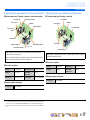
■
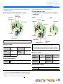
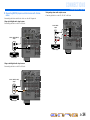
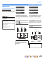
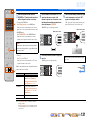
Enjoying the 7.1 channel audio source
■ 7.1-channel speaker layout (7 speakers + subwoofer)
■ Connections of speakers
■ Assigning a speaker configuration
Audio from a 7.1-channel audio source can be played back with no degradation with this speaker
configuration.
FRONT jacks Front L/R speakers SURROUND BACK jacks Surround back L/R speakers
CENTER jack Center speaker SUBWOOFER
(PRE OUT) jack
Subwoofer
SURROUND jacks Surround L/R speakers
Power Amp Assign 7ch Normal (Default)
Front L speaker
Front R speaker
Subwoofer
Center speaker
Surround L speaker
Surround R speaker
Surround back R speaker
Surround back L speaker J1
30 cm or more
J
1 : The sound of surround back channel can also be output from a single surround back speaker. When only one surround back
speaker is used, connect it to the SURROUND BACK L (SINGLE) jack and place it directly behind the listening position.

CONNECTIONS
Connecting speakers
En 17
■
Adding the front presence speakers for a richer sound field effect
■ Presence speaker layout (7 speakers + subwoofer + front presence speakers)
■ Connections of speakers
■ Assigning a speaker configuration
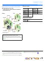
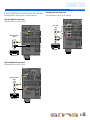
■
Enjoying the audio source without surround back speakers
■ 5.1-channel speaker layout (5 speakers + subwoofer)
■ Connections of speakers
■ Assigning a speaker configuration
This unit automatically selects the front presence or surround back speakers to output sounds
according to the selected sound program.
When the sound program is changed, the speakers that output the sound are switched between the
front presence speakers and surround back speakers automatically. J2
FRONT jacks Front L/R speakers SURROUND BACK jacks Surround back L/R speakers
CENTER jack Center speaker SUBWOOFER
(PRE OUT) jack
Subwoofer
SURROUND jacks Surround L/R speakers EXTRA SP1 jacks Front presence L/R speakers
Power Amp Assign 7ch Normal (Default)
Front L speaker
Front R speaker
Subwoofer
Center speaker
Surround L speaker
Surround R speaker
Front presence R speaker
Front presence L
speaker
Surround back R speaker
Surround back L speaker J1
30 cm or more
This unit can mix 7.1-channel audio source down to 5.1-channel sound. This enables 7.1-channel
sound without surround back speakers.
FRONT jacks Front L/R speakers SURROUND jacks Surround L/R speakers
CENTER jack Center speaker SUBWOOFER
(PRE OUT) jack
Subwoofer
Power Amp Assign 7ch Normal (Default)
Front L speaker
Front R speaker
Subwoofer
Center speaker
Surround L speaker
Surround R speaker
J
1 : The sound of surround back channel can also be output from a single surround back speaker. When only one surround back
speaker is used, connect it to the SURROUND BACK L (SINGLE) jack and place it directly behind the listening position.
J
2 : Sound cannot be output from the surround back speakers when it is output from the speakers connected to the EXTRA SP1
jacks.

CONNECTIONS
Connecting speakers
En 18
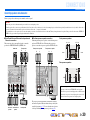
■
Using the front speakers that support bi-amp connections for a
high quality sound
■ 5.1-channel speaker layout (Front speakers (Bi-amp) + 3 speakers)
■ Connections of speakers
■ Assigning a speaker configuration
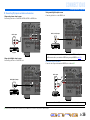
■
Using speakers in two rooms (Zone2 function)
■ 7.1-channel speaker layout + Zone2
(7 speakers (in main zone) + subwoofer (in main zone) + front speakers (in
secondary zone))
■ Connections of speakers
■ Assigning a speaker configuration
Using the front speakers that support bi-amp connections reproduces a high quality sound.
FRONT jacks Front L/R speakers
(bi-amp)
SURROUND BACK jacks Front L/R speakers (bi-amp)
CENTER jack Center speaker SUBWOOFER
(PRE OUT) jack
Subwoofer
SURROUND jacks Surround L/R speakers
Power Amp Assign 5ch BI-AMP
Front L speaker
(Bi-amp connection)
Front R speaker
(Bi-amp connection)
Center speaker
Surround L speaker
Surround R speaker
Subwoofer
In addition to the main room, speakers in another room can also be controlled.
When the built-in amplifier assigned to speakers in another room is turned on, sound output
automatically switches from the surround back speakers to the speakers in the other room. J2
FRONT jacks Front L/R speakers SURROUND BACK jacks Surround back L/R speakers
CENTER jack Center speaker SUBWOOFER
(PRE OUT) jack
Subwoofer
SURROUND jacks Surround L/R speakers EXTRA SP1 jacks J3 Zone2 speakers
Power Amp Assign 7ch + 1ZONE
Front L speaker
Front R speaker
Center speaker
Subwoofer
Surround R speaker
Surround L speaker
Surround back L speaker J1
Surround back R
speaker
30 cm or more
Front R speaker
Front L speaker
Main zone Zone2
J
1 : The sound of surround back channel can also be output from a single surround back speaker. When only one surround back
speaker is used, connect it to the SURROUND BACK L (SINGLE) jack and place it directly behind the listening position.
J
2 : Sound cannot be output from the surround back speakers when it is output from the speakers connected to the EXTRA SP1
jacks.
J
3 : EXTRA SP1 jacks can also be assigned to the Zone3 speakers with “Power Amp Assign” (☞p. 99).

CONNECTIONS
Connecting speakers
En 19
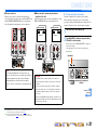
■
Using speakers in three rooms (Zone2 and Zone3 functions)
■ 7.1-channel speaker layout + Zone2 + Zone3
(7 speakers (in main zone) + subwoofer (in main zone) + front speakers (in
secondary and tertiary zones))
■ Connections of speakers
■ Assigning a speaker configuration
In addition to the main room, speakers in other two rooms can also be controlled.
When the built-in amplifier assigned to speakers in another room is turned on, sound output
automatically switches from the surround back and/or surround speakers to the speakers in the other
rooms. J2, J3
Front L speaker
Front R speaker
Center speaker
Subwoofer
Surround R
speaker
Surround L speaker
Surround back L speaker J1
Surround back
R speaker
30 cm or
more
Zone2
Zone3
Front R
speaker
Front R
speaker
Front L speaker
Front L speaker
Main zone
FRONT jacks Front L/R speakers SUBWOOFER
(PRE OUT) jack
Subwoofer
CENTER jack Center speaker EXTRA SP1 jacks J4 Zone2 speakers
SURROUND jacks Surround L/R speakers EXTRA SP2 jacks J5 Zone3 speakers
SURROUND BACK jacks Surround back L/R
speakers
Power Amp Assign 7ch + 2ZONE
J
1 : The sound of surround back channel can also be output from a single surround back speaker. When only one surround back
speaker is used, connect it to the SURROUND BACK L (SINGLE) jack and place it directly behind the listening position.
J
2 : Sound cannot be output from the surround back speakers when it is output from the speakers connected to the EXTRA SP1
jacks.
J
3 : Sound cannot be output from the surround speakers when it is output from the speakers connected to the EXTRA SP2 jacks.
J
4 : EXTRA SP1 jacks can also be assigned to the Zone3 speakers with “Power Amp Assign” (☞p. 99).
J
5 : EXTRA SP2 jacks can also be assigned to the Zone2 speakers with “Power Amp Assign” (☞p. 99).

CONNECTIONS
Connecting speakers
En 20
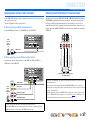
Connecting speakers and subwoofers
Connect your speakers to their respective terminals on the rear panel.
■ Front/Center/Surround/Surround back speaker and
Subwoofer connection
When connecting only one surround back speaker, connect the
speaker to the SURROUND BACK L (SINGLE) jacks.
■ Front/rear presence speaker connection
When using the front presence speakers, connect the front presence
speakers to EXTRA SP1 jacks. When using the rear presence
speakers, connect the rear presence speakers to EXTRA SP2 jacks.
The presence speakers supplement the sound from the front and
surround back speakers with extra ambient effects produced by the
sound field programs (☞
p. 57). You can adjust the vertical position
of dialogues with using the front presence speakers (☞
p. 61).
Front presence speakers
Rear presence speakers
CAUTION
• Remove the power cable of this unit from the power outlet before connecting the speakers.
• Generally speaker cables consist of two parallel insulated cables. One of these cables is a different color, or has a line running along it, to indicate different polarity. Insert the different colored (or lined) cable into the “+”
(positive, red) terminal on this unit and the speakers, and the other cable into the “–” (negative, black) terminal.
• Be careful that the core of the speaker cable does not touch anything or come into contact with the metal areas of this unit. This may damage this unit or the speakers. If the speaker cables short circuit, “CHECK SP
WIRES!” will appear on the front panel display when this unit is switched on.
SURROUND SURROUND BACK/
SPEAKERS
CENTER
SINGLE
FRONT
BI-AMP
(FRONT)
1
EXTRA
S
P1
ZO
NE2
/
Z
ON
F.PRESE
N
SPEAKERS
A
V 2 AV
3
A
V
4
HDMI
AV
5
AV
6
A
V 7
AV
3
AV
4
U
RR
OU
ND
SU
R. BA
C
K
SU
BW
OO
FE
R
C
ENTER
MU
LTI
C
H INP
UT
O
MP
O
NENT VIDE
O
M
O
NIT
O
R
OU
T
/
Z
O
NE
OUT
Z
ONE OU
T
P
RE OUT
ZO
NE
2
Z
O
NE 3
/
R. PRESENC
E
F
R
O
NT
/
F. PRESENCE
Y
P
B
P
R
P
R
Y
P
B
P
R
C
D
SU
RR
OU
ND
SU
R. BA
C
K
C
ENTE
R
(
REAR
)
(SINGLE)
SUBWOOFER
()()
2
RS-232
IN
1
2
2
1
OUT
IN
OU
T
REM
O
T
E
TRI
GG
ER
OUT
+
12
V
0.1
A
MAX
.
/
DVD
)
Subwoofer
Center speaker
Front speaker
Surround
speaker
Surround back
speaker
RL
RL RL
EXTRA SP1
ZONE2/ZONE3/
F.PRESENCE
AV 7
OUT
AC IN
FRONT
RS-232C
2
1
TRIGGER
OUT
2V 0.1A MAX.
ZONE2/ZONE3/
R.PRESENCE
EXTRA SP2
R.
SURROUND
AV 1
AV 2
AV 3
AV 1
AV 3
AV 4
AV 2
CD)
DIO 2
AUDIO 3
AUDIO 4
FRONT
SURROUND
SUR. BACK
SUBWOOFER
CENTER
MULTI CH INPUT
COMPONENT VIDEO
OAXIAL
OUT
ZONE O
ZO
Y
P
B
P
R
Y
P
B
P
R
A
B
C
D
(1 BD/DVD)
Front presence speaker
RL
Rear presence speaker
RL
• Connection of presence speakers is recommended to take full
advantage of the effects of CINEMA DSP sound programs.
• Place the rear presence left and right speakers so that the distance
between the rear presence left and right speakers is same as the
distance between front presence left and right speakers.
0.5 – 1 m 0.5 – 1 m
FPL FPR
LR
1.8 m 1.8 m
RPR RPL
SL
1.8 m
SR SBLSBR
1.8 m
Sayfa yükleniyor ...
Sayfa yükleniyor ...
Sayfa yükleniyor ...
Sayfa yükleniyor ...
Sayfa yükleniyor ...
Sayfa yükleniyor ...
Sayfa yükleniyor ...
Sayfa yükleniyor ...
Sayfa yükleniyor ...
Sayfa yükleniyor ...
Sayfa yükleniyor ...
Sayfa yükleniyor ...
Sayfa yükleniyor ...
Sayfa yükleniyor ...
Sayfa yükleniyor ...
Sayfa yükleniyor ...
Sayfa yükleniyor ...
Sayfa yükleniyor ...
Sayfa yükleniyor ...
Sayfa yükleniyor ...
Sayfa yükleniyor ...
Sayfa yükleniyor ...
Sayfa yükleniyor ...
Sayfa yükleniyor ...
Sayfa yükleniyor ...
Sayfa yükleniyor ...
Sayfa yükleniyor ...
Sayfa yükleniyor ...
Sayfa yükleniyor ...
Sayfa yükleniyor ...
Sayfa yükleniyor ...
Sayfa yükleniyor ...
Sayfa yükleniyor ...
Sayfa yükleniyor ...
Sayfa yükleniyor ...
Sayfa yükleniyor ...
Sayfa yükleniyor ...
Sayfa yükleniyor ...
Sayfa yükleniyor ...
Sayfa yükleniyor ...
Sayfa yükleniyor ...
Sayfa yükleniyor ...
Sayfa yükleniyor ...
Sayfa yükleniyor ...
Sayfa yükleniyor ...
Sayfa yükleniyor ...
Sayfa yükleniyor ...
Sayfa yükleniyor ...
Sayfa yükleniyor ...
Sayfa yükleniyor ...
Sayfa yükleniyor ...
Sayfa yükleniyor ...
Sayfa yükleniyor ...
Sayfa yükleniyor ...
Sayfa yükleniyor ...
Sayfa yükleniyor ...
Sayfa yükleniyor ...
Sayfa yükleniyor ...
Sayfa yükleniyor ...
Sayfa yükleniyor ...
Sayfa yükleniyor ...
Sayfa yükleniyor ...
Sayfa yükleniyor ...
Sayfa yükleniyor ...
Sayfa yükleniyor ...
Sayfa yükleniyor ...
Sayfa yükleniyor ...
Sayfa yükleniyor ...
Sayfa yükleniyor ...
Sayfa yükleniyor ...
Sayfa yükleniyor ...
Sayfa yükleniyor ...
Sayfa yükleniyor ...
Sayfa yükleniyor ...
Sayfa yükleniyor ...
Sayfa yükleniyor ...
Sayfa yükleniyor ...
Sayfa yükleniyor ...
Sayfa yükleniyor ...
Sayfa yükleniyor ...
Sayfa yükleniyor ...
Sayfa yükleniyor ...
Sayfa yükleniyor ...
Sayfa yükleniyor ...
Sayfa yükleniyor ...
Sayfa yükleniyor ...
Sayfa yükleniyor ...
Sayfa yükleniyor ...
Sayfa yükleniyor ...
Sayfa yükleniyor ...
Sayfa yükleniyor ...
Sayfa yükleniyor ...
Sayfa yükleniyor ...
Sayfa yükleniyor ...
Sayfa yükleniyor ...
Sayfa yükleniyor ...
Sayfa yükleniyor ...
Sayfa yükleniyor ...
Sayfa yükleniyor ...
Sayfa yükleniyor ...
Sayfa yükleniyor ...
Sayfa yükleniyor ...
Sayfa yükleniyor ...
Sayfa yükleniyor ...
Sayfa yükleniyor ...
Sayfa yükleniyor ...
Sayfa yükleniyor ...
Sayfa yükleniyor ...
Sayfa yükleniyor ...
Sayfa yükleniyor ...
Sayfa yükleniyor ...
Sayfa yükleniyor ...
Sayfa yükleniyor ...
Sayfa yükleniyor ...
Sayfa yükleniyor ...
Sayfa yükleniyor ...
Sayfa yükleniyor ...
Sayfa yükleniyor ...
Sayfa yükleniyor ...
Sayfa yükleniyor ...
Sayfa yükleniyor ...
Sayfa yükleniyor ...
Sayfa yükleniyor ...
Sayfa yükleniyor ...
Sayfa yükleniyor ...
Sayfa yükleniyor ...
Sayfa yükleniyor ...
Sayfa yükleniyor ...
Sayfa yükleniyor ...
Sayfa yükleniyor ...
Sayfa yükleniyor ...
Sayfa yükleniyor ...
Sayfa yükleniyor ...
Sayfa yükleniyor ...
Sayfa yükleniyor ...
Sayfa yükleniyor ...
Sayfa yükleniyor ...
Sayfa yükleniyor ...
Sayfa yükleniyor ...
Sayfa yükleniyor ...
Sayfa yükleniyor ...
Sayfa yükleniyor ...
Sayfa yükleniyor ...
Sayfa yükleniyor ...
Sayfa yükleniyor ...
Sayfa yükleniyor ...
-
 1
1
-
 2
2
-
 3
3
-
 4
4
-
 5
5
-
 6
6
-
 7
7
-
 8
8
-
 9
9
-
 10
10
-
 11
11
-
 12
12
-
 13
13
-
 14
14
-
 15
15
-
 16
16
-
 17
17
-
 18
18
-
 19
19
-
 20
20
-
 21
21
-
 22
22
-
 23
23
-
 24
24
-
 25
25
-
 26
26
-
 27
27
-
 28
28
-
 29
29
-
 30
30
-
 31
31
-
 32
32
-
 33
33
-
 34
34
-
 35
35
-
 36
36
-
 37
37
-
 38
38
-
 39
39
-
 40
40
-
 41
41
-
 42
42
-
 43
43
-
 44
44
-
 45
45
-
 46
46
-
 47
47
-
 48
48
-
 49
49
-
 50
50
-
 51
51
-
 52
52
-
 53
53
-
 54
54
-
 55
55
-
 56
56
-
 57
57
-
 58
58
-
 59
59
-
 60
60
-
 61
61
-
 62
62
-
 63
63
-
 64
64
-
 65
65
-
 66
66
-
 67
67
-
 68
68
-
 69
69
-
 70
70
-
 71
71
-
 72
72
-
 73
73
-
 74
74
-
 75
75
-
 76
76
-
 77
77
-
 78
78
-
 79
79
-
 80
80
-
 81
81
-
 82
82
-
 83
83
-
 84
84
-
 85
85
-
 86
86
-
 87
87
-
 88
88
-
 89
89
-
 90
90
-
 91
91
-
 92
92
-
 93
93
-
 94
94
-
 95
95
-
 96
96
-
 97
97
-
 98
98
-
 99
99
-
 100
100
-
 101
101
-
 102
102
-
 103
103
-
 104
104
-
 105
105
-
 106
106
-
 107
107
-
 108
108
-
 109
109
-
 110
110
-
 111
111
-
 112
112
-
 113
113
-
 114
114
-
 115
115
-
 116
116
-
 117
117
-
 118
118
-
 119
119
-
 120
120
-
 121
121
-
 122
122
-
 123
123
-
 124
124
-
 125
125
-
 126
126
-
 127
127
-
 128
128
-
 129
129
-
 130
130
-
 131
131
-
 132
132
-
 133
133
-
 134
134
-
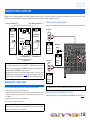 135
135
-
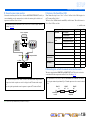 136
136
-
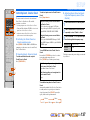 137
137
-
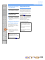 138
138
-
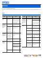 139
139
-
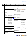 140
140
-
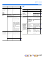 141
141
-
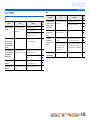 142
142
-
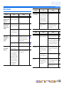 143
143
-
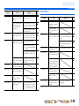 144
144
-
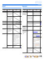 145
145
-
 146
146
-
 147
147
-
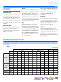 148
148
-
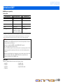 149
149
-
 150
150
-
 151
151
-
 152
152
-
 153
153
-
 154
154
-
 155
155
-
 156
156
-
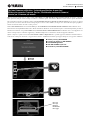 157
157
-
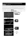 158
158
-
 159
159
-
 160
160
-
 161
161
-
 162
162
-
 163
163
-
 164
164
-
 165
165
-
 166
166


Diğer dillerde
- français: Yamaha RX-V3067 Le manuel du propriétaire
- italiano: Yamaha RX-V3067 Manuale del proprietario
- svenska: Yamaha RX-V3067 Bruksanvisning
- Deutsch: Yamaha RX-V3067 Bedienungsanleitung
- English: Yamaha RX-V3067 Owner's manual
- dansk: Yamaha RX-V3067 Brugervejledning
- русский: Yamaha RX-V3067 Инструкция по применению
- suomi: Yamaha RX-V3067 Omistajan opas
- Nederlands: Yamaha RX-V3067 de handleiding
- română: Yamaha RX-V3067 Manualul proprietarului