
DOC024.98.93001
ORBISPHERE Model
410 Analyzer
11/2017, Edition 11
Basic User Manual
Allgemeines Benutzerhandbuch
Manuel d'utilisation de base
Manual básico del usuario
Manuale dell'utente di base
Základní uživatelská příručka
Grundlæggende brugervejledning
Basisgebruikershandleiding
Основно ръководство за потребителя
Alapvető felhasználói kézikönyv
Начальное руководство пользователя
Temel Kullanıcı Kılavuzu
Podstawowa instrukcja obsługi
Manual de utilizare de bază
Osnovni korisnički priručnik
Allmän användarhandbok

English..............................................................................................................................3
Deutsch.......................................................................................................................... 24
Français......................................................................................................................... 47
Español.......................................................................................................................... 69
Italiano............................................................................................................................ 91
Čeština......................................................................................................................... 112
Dansk............................................................................................................................134
Nederlands................................................................................................................. 155
български................................................................................................................... 177
Magyar......................................................................................................................... 200
Русский........................................................................................................................222
Türkçe...........................................................................................................................246
Polski............................................................................................................................ 267
Română....................................................................................................................... 291
Hrvatski........................................................................................................................ 313
Svenska....................................................................................................................... 335
2

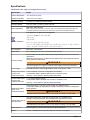
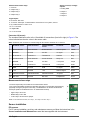
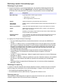
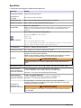
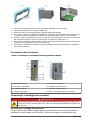
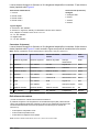
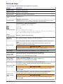
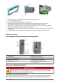
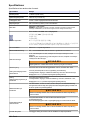
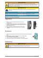
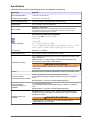
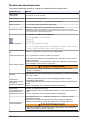
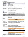
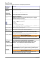
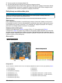
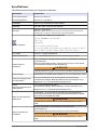
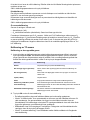
Specifications
Specifications are subject to change without notice.
Specification Details
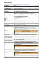
Ambient temperature –5 to 50°C (23 to 122°F)
Storage temperature –20 to 70°C (–4 to 158°F)
Operating humidity 0 to 95% non-condensing relative humidity
Operating altitude From 0 to 2,000 m. (6,550 ft.) above sea level
EMC requirements
EN61326-1: EMC Directive
Note: The wall mount instrument is a Class A product. In a domestic environment this product may
cause radio interference in which case the user may be required to take adequate measures.
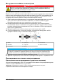
Korean registration
User Guidance for EMC Class A Equipment
업무용을 위한 EMC 등급 A 장치에 대한
사용자 지침
사용자안내문
A 급 기기 ( 업무용 방송통신기자재 )
이 기기는 업무용 (A 급 ) 전자파적합기기로서 판매자 또는 사용자는 이 점을 주의하시기
바라며 , 가정외의 지역에서 사용하는 것을 목적으로 합니다.
CE compliance EN61010-1: LVD Directive
Safety rating ETL, conforming to UL 61010-1 and CSA 22.2 No. 61010-1
Enclosure ratings
IP 65; Totally protected against dust; Protected against low pressure jets of water from
all directions.
NEMA 4X (wall mount only); Totally protected against dust; Protected against pressure
jets of water from all directions.
W A R N I N G
Enclosure rating does not apply to external power supply for benchtop instruments.
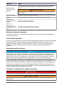
Power supply Universal 100 VAC to 240 VAC @ 50/60Hz - 40VA; 10 to 30 VDC - 30W
Analog current output
version on the
measurement board
4-20 mA (default) or 0-20 mA (configuration with software);
3 configurable outputs; Maximum load: 500 ohm; Sensitivity: 20μA;
Accuracy: ± 0.5% (between operating temperature limits)
Analog voltage output
version on the
measurement board
0- 5 V output (hardware option);
3 configurable outputs; Minimum load: 10 KOhm; Sensitivity: 5 mV;
Accuracy: ± 0.5% (between operating temperature limits)
Measurement alarm
relays on the
measurement board
Three alarm relays; 1A-30 VAC or 0.5A-50 VDC on a resistance load
Configurable to Normally Open [NO] or Normally Closed [NC] contacts by changing the
jumper positions
W A R N I N G
Potential Electrocution Hazard. Connect only safety low voltage < 33 VAC RMS
System alarm relay on
the main board
One system alarm relay; 1A-30 VAC or 0.5A-50 VDC on a resistance load
Normally closed [NC] (NO relay also available) when instrument is turned on
W A R N I N G
Potential Electrocution Hazard. Connect only safety low voltage < 33 VAC RMS
Thermal cut off Prevents ageing of sensors when exposed to high temperatures
Options RS-485 or PROFIBUS-DP (optional); USB host; Ethernet 10/100 Base-T
English 3

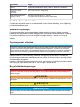
Specification Details
Wall and pipe mount
instrument
(H x D x W)
236.5 x 160 x 250 mm; Weight 4.25 kg
9.31 x 6.30 x 9.84 in.; Weight 8.82 lbs
Panel mount
instrument
(housing) (H x D x W)
156 (123) x 250 x 220 (214) mm; Weight 3.35 kg
6.14 (4.84) x 9.84 x 8.86 (8.43) in.; Weight 6.62 lbs
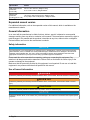
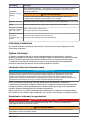
Expanded manual version
For additional information, refer to the expanded version of this manual, which is available on the
manufacturer's website.
General information
In no event will the manufacturer be liable for direct, indirect, special, incidental or consequential
damages resulting from any defect or omission in this manual. The manufacturer reserves the right to
make changes in this manual and the products it describes at any time, without notice or obligation.
Revised editions are found on the manufacturer’s website.
Safety information
N O T I C E
The manufacturer is not responsible for any damages due to misapplication or misuse of this product including,
without limitation, direct, incidental and consequential damages, and disclaims such damages to the full extent
permitted under applicable law. The user is solely responsible to identify critical application risks and install
appropriate mechanisms to protect processes during a possible equipment malfunction.
Please read this entire manual before unpacking, setting up or operating this equipment. Pay
attention to all danger and caution statements. Failure to do so could result in serious injury to the
operator or damage to the equipment.
Make sure that the protection provided by this equipment is not impaired. Do not use or install this
equipment in any manner other than that specified in this manual.
Use of hazard information
D A N G E R
Indicates a potentially or imminently hazardous situation which, if not avoided, will result in death or serious injury.
W A R N I N G
Indicates a potentially or imminently hazardous situation which, if not avoided, could result in death or serious
injury.
C A U T I O N
Indicates a potentially hazardous situation that may result in minor or moderate injury.
N O T I C E
Indicates a situation which, if not avoided, may cause damage to the instrument. Information that requires special
emphasis.
4 English

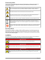
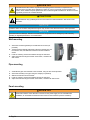
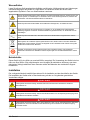
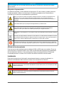
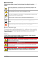
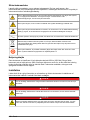
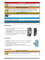
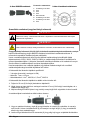
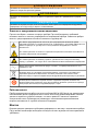
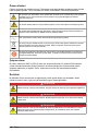
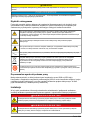
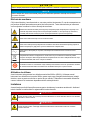
Precautionary labels
Read all labels and tags attached to the instrument. Personal injury or damage to the instrument
could occur if not observed. A symbol on the instrument is referenced in the manual with a
precautionary statement.
This is the safety alert symbol. Obey all safety messages that follow this symbol to avoid potential
injury. If on the instrument, refer to the instruction manual for operation or safety information.
This symbol indicates that a risk of electrical shock and/or electrocution exists.
This symbol indicates the presence of devices sensitive to Electro-static Discharge (ESD) and
indicates that care must be taken to prevent damage with the equipment.
This symbol, when noted on a product, indicates the instrument is connected to alternate current.
Electrical equipment marked with this symbol may not be disposed of in European domestic or
public disposal systems. Return old or end-of-life equipment to the manufacturer for disposal at no
charge to the user.
Products marked with this symbol indicates that the product contains toxic or hazardous substances
or elements. The number inside the symbol indicates the environmental protection use period in
years.
Operating altitude
This instrument is rated for an altitude of 2000 m (6562 ft) maximum. Use of this instrument at an
altitude higher than 2000 m can slightly increase the potential for the electrical insulation to break
down, which can result in an electric shock hazard. The manufacturer recommends that users with
concerns contact technical support.
Installation
This section provides necessary information to install and connect the analyzer. The installation of
the analyzer should be performed in accordance with relevant local regulations.
D A N G E R
Electrocution hazard. Do not connect AC power directly to a DC powered instrument.
D A N G E R
Electrocution hazard. Always remove power to the instrument before making electrical connections.
D A N G E R
Electrocution hazard. If this equipment is used outdoors or in potentially wet locations, a Ground Fault
Circuit Interrupt (GFCI/GFI) device must be used for connecting the equipment to its main power
source.
English 5

W A R N I N G
Potential Electrocution Hazard. A protective earth (PE) ground connection is required for both
100-240 VAC and 5 VDC wiring applications. Failure to connect a good PE ground connection can
result in shock hazards and poor performance due to electromagnetic interferences. ALWAYS connect
a good PE ground to the controller terminal.
C A U T I O N
Multiple hazards. Only qualified personnel must conduct the tasks described in this section of the
document.
N O T I C E
Install the device in a location and position that gives easy access to the disconnect device and its operation.
N O T I C E
Potential Instrument Damage. Delicate internal electronic components can be damaged by static electricity,
resulting in degraded performance or eventual failure.
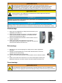
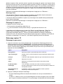
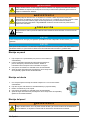
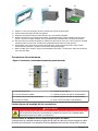
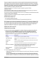
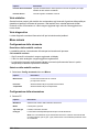
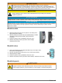
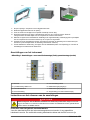
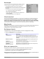
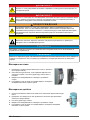
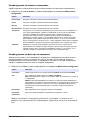
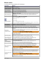
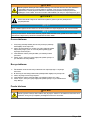
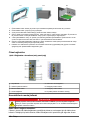
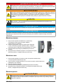
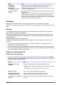
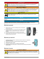
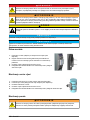
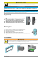
Wall mounting
1. Attach the U-bracket (provided) to the wall with two screws (not
provided).
2. Tilt the instrument slightly backwards to align the bracket pins and
the insertion slots, and slide the instrument onto the bracket as
shown.
3. Insert the 2 locking screws with washers through the side slots.
4. Adjust the instrument angle for better screen vision, and lock both
side screws.
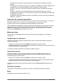
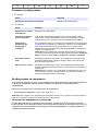
Pipe mounting
1.
Assemble the pipe mount bracket to the U-bracket, using the two screws provided.
2. Attach this assembly to the pipe using two clamps (not provided).
3. Slide the instrument onto the bracket.
4. Insert the 2 locking screws with washers through the side slots.
5. Adjust the instrument angle for better screen vision, and lock both side screws.
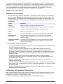
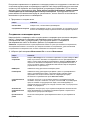
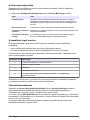
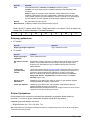
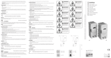
Panel mounting
W A R N I N G
Electrocution hazard. If the cable and connector for the power supply are not accessible after
installation, an accessible local disconnection means for the instrument power is mandatory.
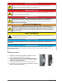
6 English

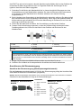
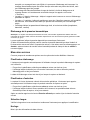
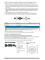
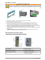
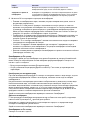
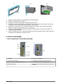
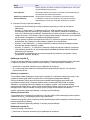
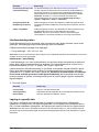
1-3 4-5 6-7
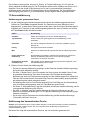
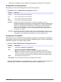
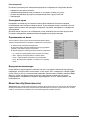
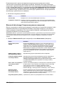
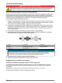
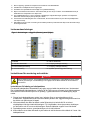
1. Cut an opening in the panel to accommodate the bracket frame provided.
2. Install the provided frame in the opening.
3. Fold the 6 tabs over the panel lips, using adjustable joint pliers.
4. Slide the instrument in the bracket frame. The instrument should go over the four "T" pins. Rotate the 4 fast
locking screws on both sides of the front panel and slide it in.
5. Rotate the 4 fast locking screws 1/4 turn twice in the lock direction as indicated on the side of the front panel.
This locks the instrument in place on the four "T" pins.
6. To access the connections inside the instrument, remove the instrument housing (six screws on the back
panel, and slide the housing back out)
7. Pass the cables through the housing, then through the cable gland (if applicable) and then perform the
connections as detailed below.
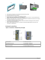
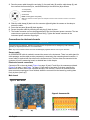
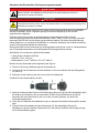
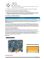
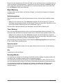
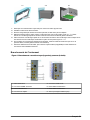
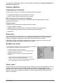
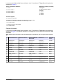
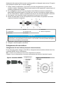
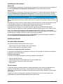
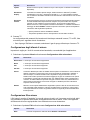
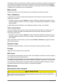
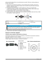
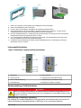
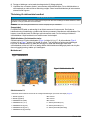
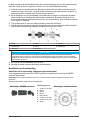
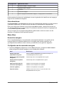
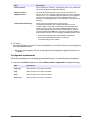
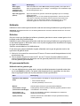
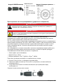
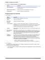
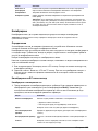
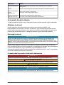
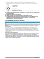
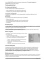
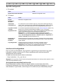
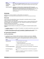
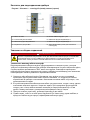
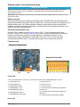
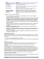
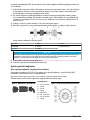
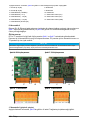
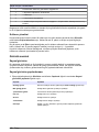
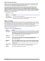
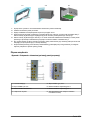
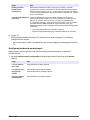
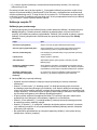
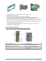
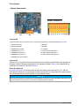
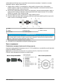
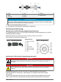
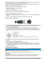
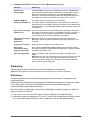
Instrument connections
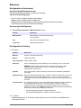
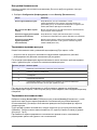
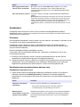
Figure 1 Connections - wall/pipe (left); panel (right)
1 Power cable 5 USB-A host connector
2 USB-B 4-pin connector 6 Input/Output 2 cable gland
3 Ethernet cable gland 7 Input/Output 1 cable gland
4 Sensor connection 8 Keylock (wall/pipe mount only)
English 7

Connectors assembly instructions
D A N G E R
Electrocution hazard. In order to maintain the NEMA/IP environmental ratings of the enclosure, use
only conduit fittings and cable glands rated for at least NEMA 4X/IP66 to route cables in to the
instrument.
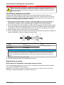
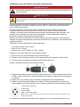
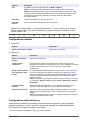
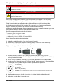
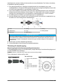
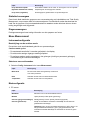
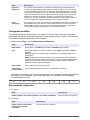
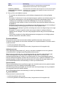
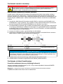
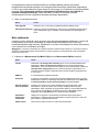
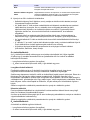
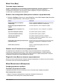
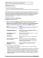
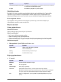
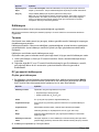
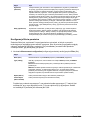
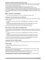
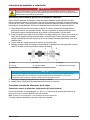
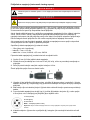
Cable gland wiring instructions
A waterproof cable gland is provided each time a cable must be connected inside the instrument.
The nickel-plated brass cable glands are EMC-types, designed so that the cable shields attach
directly to the instrument housing as a ground. Typical cable wiring instructions are detailed below.
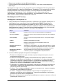
1. Unscrew the cable gland nut. Inside, the assembly is composed of a rubber gasket, and two
metal washers. Note that the ethernet gland on panel and wall mount instruments does not have
washers and the gasket is cut.
2. If wiring a sensor cable, the cable has already been prepared so simply remove the piece of
plastic protection from the exposed shielding. For other cables, strip off external insulation as
required, and 25 mm of shielding. Strip the wires about 8 mm from their ends.
3. Pass the cable through the nut, the rubber gasket, and the two washers.
4. Pinch the shield so that its entire circumference is pressed between the two washers and pass
the cable into the housing, blocking the cable gland.
1 Cable 4 Wire 7 Gasket
2 Shield 5 O-ring 8 Gland nut
3 Instrument 6 Washers
N O T I C E
It is vitally important to ensure the shielding is pinched and secured between the two washers to ensure the
shielding attaches directly to the instrument housing as a ground. Failure to do this could cause damage to
the instrument, and for sensor cables give incorrect readings.
5. Reattach and tighten the cable gland nut.
6. Attach the wires to the corresponding terminal block connections.
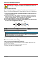
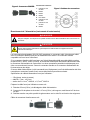
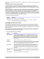
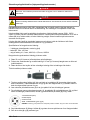
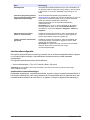
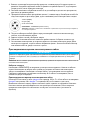
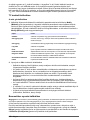
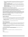
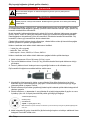
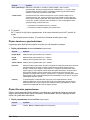
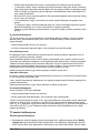
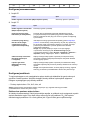
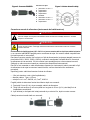
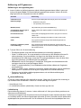
Connection to mains power supply
Power supply connection (low voltage instruments)
For low voltage instruments (10-30 VDC), connection to the mains power supply is with a 8-pin
BINDER connector (supplied).
Note: The connectors are grooved to avoid an incorrect fitting to the instrument.
Connect the power cable to the connector as follows:
8
English

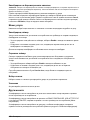
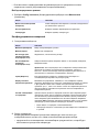
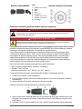
Figure 2 BINDER connector
Pin Connections:
1. Power 10-30 VDC
2. Ground
3. Ground
4. Ground
5. Not used
6. Power 10-30 VDC
7. Power 10-30 VDC
8. Earth
Figure 3 Wiring side view
Power supply connection (high voltage instruments)
D A N G E R
Multiple hazards. Only qualified personnel must conduct the tasks described in this section of the
document.
D A N G E R
Electrocution hazard. Always remove power to the instrument before making electrical connections.
High voltage instruments (100-240 VAC) have a 4-pin male connector pre-wired internally with a
male BINDER connector ready for mains connection. A compatible female connector is supplied with
the instrument.
If this female connector was supplied with a mains power plug already pre-attached (cable part
numbers 33031, 33032, 33033 and 33034) then the female connector can be plugged directly into
the instrument power connector. The two connectors are grooved to avoid an incorrect fitting. Tighten
the female connector to the instrument power connector finger-tight.
If no power cable was ordered with the equipment, a mains power plug must be connected to the
supplied female connector as described in the following procedure.
User-supplied power cable specifications:
• 3-wire (live, neutral and earth)
• cable Ø ≥ 7mm; ≤ 9.5mm
• wire selection ≥ 1mm
2
, AWG18; ≤ 2.5mm
2
, AWG14
Prepare the user-supplied power cable as follows:
1. Strip off 23 mm (0.9 ins.) of shielding from the power cable.
2. Cut back the live and neutral wires to 15 mm (0.6 ins.) in length but leave the earth wire as is.
3. Then strip off a small amount of external insulation from the three wires as required.
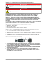
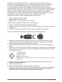
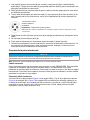
Wire the female connector as follows:
1. Take the narrow end of the connector (4) in one hand and the main body (2) in the other and
unscrew the two. Pull away the cable clamp (3) and unscrew the end plug (1) to reveal the four
parts that make up the connector.
2. Loosen the screws on the cable clamp (3) to allow enough room to pass the power cable through.
English
9

3. Pass the power cable through the end plug (1), the main body (2), and the cable clamp (3), and
then connect the three wires (live, neutral and earth) to the connector (4) as follows:
1. Live (brown)
2. Neutral (blue)
3. Not used
Earth - Earth (green and yellow)
Note: The numbers and earth symbol are stamped on the end of the connector. Ensure it is connected
correctly.
4. Slide the cable clamp (3) back onto the connector (4) and tighten the screws on the clamp to
secure the cable.
5. Screw the two parts (4) and (2) back together.
6. Secure the power cable by screwing the end plug (1) back in place.
7. The female connector can now be plugged directly into the instrument power connector. The two
connectors are grooved to avoid an incorrect fitting. Tighten the female connector to the
instrument power connector finger-tight.
Connections to electronic boards
N O T I C E
Potential Instrument Damage. Delicate internal electronic components can be damaged by static electricity,
resulting in degraded performance or eventual failure.
Note: Any loose connection wires should be bundled tightly together with the use of nylon cable ties.
Sensor cable
An ORBISPHERE cable is needed to connect the sensor to the instrument. There is a cable gland for
cable passage, and the cable must be permanently connected to the measuring board connector. A
sensor cable is required with free wires on the instrument end. The free wires are connected to the
connector J8 on the measuring board, as detailed later in this chapter.
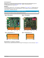
Electronic boards connectors
Connectors P8 on the main board (Figure 4 on page 10) and J7 and J8 on the measurement board
(Figure 6 on page 11 and Figure 7 on page 11) are made of two parts. Push down carefully the
black levers on either side of the connector and pull it out securely. Perform all connections with
these connectors unplugged. Once finished, attach the connectors to the boards by pushing them
firmly in place (levers up).
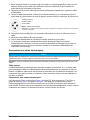
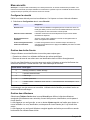
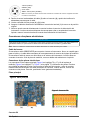
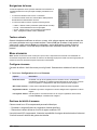
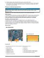
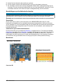
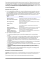
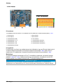
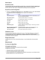
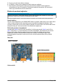
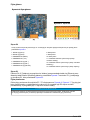
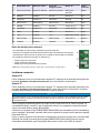
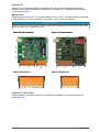
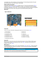
Main board
Figure 4 Main board
Figure 5 Connector P8
10 English

Connector P8
The numbers listed below refer to the 13 available P8 connections (from left to right) in Figure 5.
1. RS-485 (signal A)
2. RS-485 (signal B)
3. PROFIBUS-DP (GND)
4. PROFIBUS-DP (+ 5 V)
5. PROFIBUS-DP (signal -)
6. PROFIBUS-DP (signal +)
7. PROFIBUS-DP (signal RTS)
8. Not used
9. Not used
10. Not used
11. System alarm relay (N.O.)
12. System alarm relay (N.C.)
13. System alarm relay (Common)
Connector P3
Ethernet RJ 45. Connect the instrument to the local network by passing an ethernet cable through
the ethernet cable gland (gland location illustrated in Figure 1 on page 7) and connecting to the
P3 connector illustrated in Figure 4.
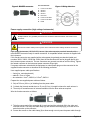
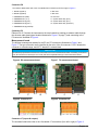
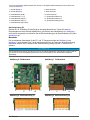
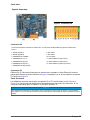
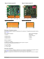
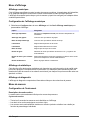
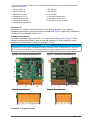
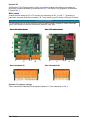
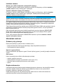
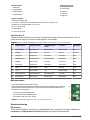
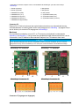
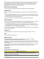
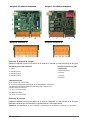
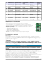
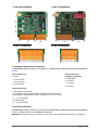
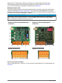
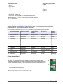
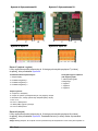
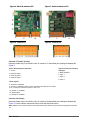
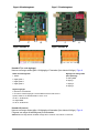
Measurement board
The different measurement boards for the EC and TC sensors are illustrated in Figure 6 and
Figure 7. The type of board is easily identified by the color of the J8 connector. For EC boards this
connector is colored orange, and for TC boards it is colored black.
N O T I C E
It is extremely important that sensors are connected to the correct measurement board. Connecting a TC sensor
to an EC measurement board (and vice versa) will cause irreparable damage to the measurement board.
Figure 6 EC measurement board Figure 7 TC measurement board
Figure 8 Connector J7 Figure 9 Connector J8
Connector J7 (inputs & outputs)
The numbers listed below refer to the 16 available J7 connections (from left to right) in Figure 8.
English
11

Measurement alarms relays:
1. Common
2. Output relay 1
3. Output relay 2
4. Output relay 3
Analog current (or voltage)
outputs:
5. Analog GND
6. Output 1
7. Output 2
8. Output 3
Digital inputs:
9. EC sensor: Not used
9. TC sensor: Hold input. To deactivate the sensor from a PLC system, connect
a dry contact between J7.9 and J7.12
10. to 11. Not used
12. Digital GND
13. to 16. Not used
Connector J8 (sensor)
The numbers listed below refer to the 10 available J8 connections (from left to right) in Figure 9. The
colors indicated are the wire colors in the sensor cable.
Note: Remember, this connector is colored orange for EC sensors and black for TC sensors.
A1100 EC sensor 31xxx EC sensor 31xxxS smart EC
sensor
TC sensor Sensor
cable
1. Guard electrode Guard electrode Guard electrode GND for power Yellow
2. RS485A+ Not used I2C-SCL V2 signal Pink
3. Thermistor A Thermistor A Thermistor A Solenoid Grey
4. Anode electrode Anode electrode Anode electrode Relay coil Red
5. RS485B Not used I2C-SDA +12V power Purple
6. Thermistor B Thermistor B Thermistor B +24V power White
7. GND Not used GND V3 signal Black
8. + 5V Not used + 5V GND for signal Green
9. Cathode electrode Cathode electrode Cathode electrode -5V power Blue
10. Not used Not used Not used Temperature Brown
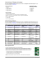
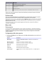
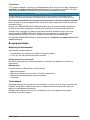
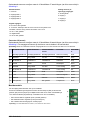
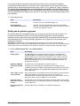
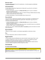
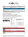
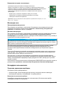
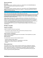
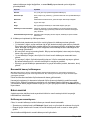
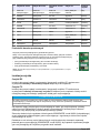
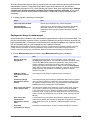
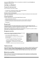
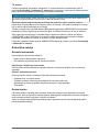
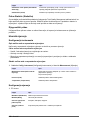
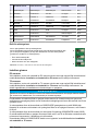
Measurement alarm relays
The three output relays are located on the measurement board.
They can be individually configured to Normally Open (NO) or to Normally Closed (NC) by
physically moving the jumper on each relay. The illustration is for the EC measurement
board (the positions are different for the TC measurement board):
• Upper relay is set to NC
• Middle relay is set to NO
• Lower relay is shown with no jumper
Note: For all measurement boards, J4 is relay 1, J5 is relay 2 and J6 is relay 3
Sensor installation
EC sensors
For EC sensor installation, servicing, and maintenance ensure you follow the instructions in the
Sensor Installation and Maintenance manual that was supplied with the instrument.
12
English

TC sensors
For TC sensor installation, servicing and maintenance ensure you follow the instructions in the TC
Sensor Installation and Maintenance manual that was supplied with the instrument. Pay particular
attention to the installation and connection of the purge gas supply.
N O T I C E
Do not place the TC sensor into a liquid sample until a constant supply of dry purge gas has been connected, as
liquid could condense inside the measuring chamber and cause damage to the thermal conductor chip.
To ensure the continuation of purge gas while the sensor is in contact with the sample, it is highly
recommended to use a backup purge gas cylinder with an automatic changeover valve that activates
when the first cylinder is empty.
The use of an ORBISPHERE Model 29089 gas regulator (or similar) is also recommended to deliver
a constant, pressure regulated supply of dry purge gas to the sensor, filtered to 40 μm.
In addition, and to prevent any damage to the sensor electronics, the use of a purge safety backup
unit (ORBISPHERE Model 32605) is highly recommended to ensure the supply of purge gas remains
uninterrupted to the sensor in the event of a mains power outage.
The above ORBISPHERE accessories are explained in more detail in the TC Sensor Installation
and Maintenance manual.
User interface
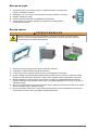
Instrument controls
The instrument front panel provides:
• A touch screen acting as display, touch pad and keyboard.
• A LED, showing when the instrument is on.
Turning instrument On and Off
There is no power switch on the instrument. The mains must be disconnected to turn the instrument
off.
Measurement window
The main (numeric) measurement window continuously displays:
• Sensor measured values
• Measured sensor trends (for the last 10 minute to last hour)
• Measured sensor data alarm limits and other events
• Temperature
Touch screen
The user interface on the front panel is a touch screen providing easy selection through menus. All
the measurement, configuration, calibration and standard service routines can be called by pressing
buttons and menu bars on screen.
The display can be configured to only show a sensor measurement, or to show a parameterized
graphic representation of the last measurements.
English
13

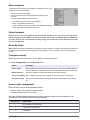
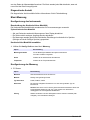
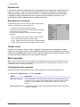
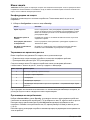
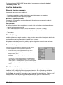
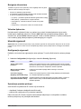
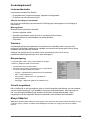
Menu navigation
Pressing the “menu” button in the header bar calls the main menu. The
display is made of three columns:
• The left shows the menu options
• The center shows a tree view of the position inside the menu
structure
• The right has the following generic controls:
• Up - Return to previous menu (one step back)
• Main - Jump directly to main menu
• Close - Close the menu and go back to the measurement display.
• Help - Help topics concerning current menu
Virtual keyboard
When a value or text is to be edited a virtual keyboard will appear on screen and can be used like a
standard keyboard. Press CAP to access special keys. When input is complete press the Enter key
to confirm and exit the virtual keyboard. During editing, the edited field name is displayed along with
units where applicable.
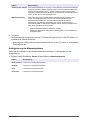
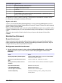
Security menu
Note: When the instrument is started for the first time security is disabled. It is highly recommended that each user
be entered into the system and given appropriate access rights as soon as possible to avoid any unauthorized
access.
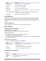
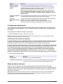
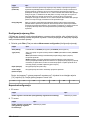
Configure security
Define access levels for all users . This requires a user access level 4.
1. Select Configuration from the Security menu.
Option Description
Access rights When enabled only registered users can access the menus. When disabled (default)
all menus are freely accessible and no ID is recorded against any action in the log file.
Max session time The user is logged out automatically when the time limit is reached.
User action logging When enabled every action from a logged on user is recorded in a user log file.
User action log file The log file is a rolling buffer recording recent actions. Press Clear to empty the log
file.
Access rights management
Each user has a unique ID and password used to:
• Allow or deny a user to perform specific actions
• To trace all actions by "ID" in a log file
Once the ID and password are entered the user is allowed to perform actions according to the
"Access level" that has been attributed by the Manager:
Access level Typical rights
0 View parameters, change views
1 + Start / Stop measurements
2 + Calibration
14 English

Access level Typical rights
3 + Modify parameters
4 + Modify table "User Access level" + Enable/Disable "Access right"
At startup all menus are locked and a valid ID and password combination is required to get access
beyond the standard measurement view.
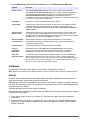
User management
Select Access table from the Security menu to show the list of registered users (a maximum of
99 users allowed). They are listed by name, ID, password and access level.
Pressing on an empty line or the Add button displays a window to add a new user. User name, ID,
password (minimum 4 characters) and access level (1 to 4) are required.
Pressing on a registered user displays a window for editing or deleting that user.
View menu
Numeric view
This is the default view and shows the measurement value, sample temperature value, and a graph
showing the measurements during the set time frame. The display is refreshed after each
measurement cycle which can be configured to suit user requirements.
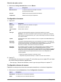
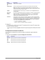
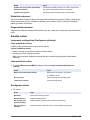
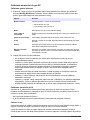
Numeric view configuration
1. Select Configure from the View menu followed by Conf. numeric view to customize the display:
Option Description
Display temperature Selct Channel temperature to display the sample temperature.
Display mini graph Check the box to display the graph.
Display time base Check the box to display the time base.
Upper bound Adjust graph upper limit.
Lower bound Adjust graph lower limit.
Time base Adjust graph time span.
Grid button Set up the graph to display the x or y axes, grid, or alarm thresholds.
Auto scale update button Automatically set the graph upper and lower bounds to best fit the actual values
displayed.
Clean button Clear the graph being displayed and restart.
Statistic view
This feature offers statistical data to match with Total Quality Management tools to better analyze
how a process behaves. The statistics are calculated from the data in the measurement file and
values updated each time a new measurement is added.
Diagnostic view
The diagnostic view contains important information but is only really useful for troubleshooting
purposes.
English
15

Measurement menu
Instrument configuration
Continuous mode description
Continuous mode is typically used for process measurement.
Continuous mode cycle
• Every 2 sec. measurements are refreshed on the display
• The relays and the analog outputs are updated
• Measurements are continuously stored in memory (volatile and non volatile memory) according to
individual settings
Continuous mode selection
1. Select Config. instrument from the Measurement menu:
Option Description
Measurement mode Measurement mode is locked on Continuous
for on line process.
Pressure Select the barometric pressure units.
Temperature Select the temperature units.
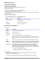
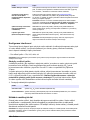
Measurement configuration
1. EC sensor
Option Description
Membrane Sensor’s membrane number selection.
Medium Liquid or gas phase.
Gas unit type Partial, Fraction, Dissolved.
Gas unit The list of available units depends on unit type selected above.
Note: This is the gas concentration measured by the EC sensor. When a composite unit
is selected (e.g. ppm » ppb) the unit will change depending on the range of the value to
display.
Liquid When medium is liquid, select water or a liquid with a different solubility (if available).
Display
resolution:
Maximum resolution depends on gas, membrane and unit. A maximum of 5 digits can be
displayed. Decimals can be limited to 0, 1, 2 or 3 decimals for easier reading. That does
not affect the actual resolution of data measured and stored, but only the data displayed.
Thermal cutoff: To protect the sensor, the thermal cutoff function allows for setting a sample high
temperature limit. If exceeded (during a Cleaning In Place cycle for example) the
electrical signal to the sensor is cut off, the measurement session is suspended and the
system displays a HOT alarm message. The system resumes when temperature drops
to 90% of the specified cutoff temperature.
• Thermal cut off options: Disabled / enabled.
• Thermal cut off temperature: To be set according to conditions.
2. TC sensor
The measurement configuration for a TC sensor is the same as for an EC sensor with the
addition of one extra selection criteria:
• Purge gas: From the drop-down list, select the purge gas being used for the TC sensor.
16
English

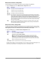
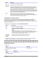
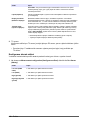
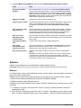
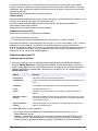
Measurement alarms configuration
Set the thresholds for the low/high concentration levels according to the application.
1. Select the Alarms button on the Measurement configuration screen:
Option Description
Low Low 2nd stage for too low concentration alarm.
Low 1st stage for too low concentration alarm.
High 1st stage for too high concentration alarm.
High High 2nd stage for too high concentration alarm.
Hysteresis The hysteresis is used to prevent relay flickering when the measurement is just at the alarm
levels. Set this to a minimum but enough to eliminate flickering. For example, if the High Alarm
is set to 40 ppb and the Hysteresis is set to 10% then the High Alarm is activated once the
measurement reaches 40 ppb but only deactivated once it drops below 36 ppb. With the Low
Alarm the opposite is true in that if the Low Alarm is set to 20 ppb and the Hysteresis set to 10%
then the Low Alarm is activated when the measurement drops below 20 ppb and deactivated
when it rises above 22 ppb.
Delay The delay in seconds, before alarms go on whenever concentration values go above ”High
alarms” or below “Low alarms”. Set this to a minimum value, but enough to avoid alarms for
non-representative peaks beyond the set level.
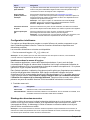
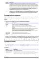
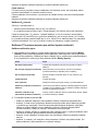
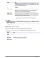
Measurement filter configuration
The filters are aimed at “flattening” the measurement curve in situations where the process shows
atypical peak values that could otherwise hamper the interpretation of measurement readings. The
filter is applied on the last set of measurements each time a measurement is taken.
1. Select the Filter button on the Measurement configuration screen:
Option Description
State Set the filters to Enabled or Disabled.
Type If enabled set the filter to Mean or Median.
Mean is the mathematical average of the last set (depth) of measurement values.
Median allows for eliminating atypical peak measurement values and averaging the
remaining ones. The calculation sorts the last measurement set (depth) by values, then
ignores the highest and lowest values and averages the remaining values (central depth).
Depth Number of measurements that make up a set.
Central depth Number of measurements to be used to determine the average.
Example: With a depth of 7 and central depth of 5, the 7 values are sorted and the highest (7.0)
and lowest (0.9) eliminated. The average of the center 5 is calculated as 3.88:
English
17

0.9 1.1 4.0 4.3 4.4 5.6 7.0
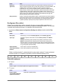
Advanced configuration
1. EC sensor
Option Description
Enable negative concentration Check as appropriate.
2. TC sensor
Option Description
Enable negative
concentration
Check as appropriate.
Hold recovery time This parameter defines the interval during which the outputs remain frozen after
the measurement is no longer on HOLD. Set the value to between OFF and
10 minutes, according to the timing of your setup.
Continuous purge
during thermal cut off
If thermal cutoff has been enabled (see Measurement configuration on page 16),
then check this box to ensure that a continuous purge of the TC sensor takes
place while the measurement session is suspended due to the thermal cutoff
temperature value being exceeded.
Note: To manually set the TC sensor into a continuous purge mode, press the
Continuous Purge button that is available from the Services - Diagnostic -
Channel x - Amplifiers menu.
Offset and slope
corrections
Enable correction as appropriate. If enabled, the correction values for offset and
slope must be entered. These values cannot be negative.
Liquid to gas factor Enable correction as appropriate. If checked, the percentage correction factor must
be entered. This value cannot be negative.
Note: If you believe you need to enable these corrections, it is advisable to contact
a Hach Lange Service Representative first.
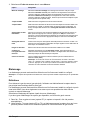
Interferences configuration
These options are available to take into account the influence of some components or gases in the
sample during measurement. All available interference corrections are disabled by default.
The following interference corrections are available:
• For oxygen measurements - CO
2
, H
2
S, Chlorine, Salt
Note: If you believe you need to enable any of the above, it is advisable to contact a Hach Lange Service
Representative first.
Interferences in oxygen measurement
In some applications, like in the beverage industry, there can be high concentrations of carbon
dioxide in the sample. Hach Lange recommends using the CO
2
interference option if a carbon
dioxide concentration of over 1% in gas phase, or 15 ppm in dissolved phase is present.
18
English

In the petroleum industry, the detection of oxygen is sometimes hampered by significant
concentrations of hydrogen sulfide in the sample. Hach Lange recommends using the H
2
S
interference option if the hydrogen sulfide concentration exceeds 0.15% in gas phase, or 5 ppm in
dissolved phase. To operate the oxygen sensor in these conditions requires using a different
sensor and electrolyte. When using this mode your system will experience sensitivity loss of about
50 times higher than the minimum sensitivity for the membrane.
1. Proceed as follows:
Option Description
CO2 or H2S Select CO
2
, H
2
S or All disabled.
Chlorinity/Salinity Select Chlorinity, Salt or All disabled. For chlorinity or salt, it is required to enter the
actual concentration in the sample.
Measured data storage
There is one measurement file which contains the data generated by the measurement cycle. The
measurement file is updated in volatile memory and regularly copied in non-volatile memory (file
back-up). At start up the measurement file in volatile memory is updated with the file from the non-
volatile memory.
Note: Data stored in volatile memory is lost when instrument is powered off; non-volatile memory is permanent. In
case of an accidental power off event the instrument resumes measurement storage after the last measurement
stored in flash.
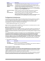
1. Select Measurement file from the Measurement menu:
Option Description
Storage mode Select No storage if data storage is not required. Select Store once to start
recording measurements. When the volatile memory is full the recording of
measurement stops. Select Rolling buffer for continuous recording of
measurements. When the volatile memory is full the latest measurement set
replaces the oldest one (first-in, first-out)
RAM time The delay between two recordings of measurement data.
FLASH time The delay between two data file transfers from volatile memory into non-volatile
memory. The last data file erases the previous one. This option is only available if
the Auto save in flash box is checked.
Save in flash now Press this button to store measurement data in flash immediately. After pressing
this button, press OK to initiate the process. A warning screen appears informing
you that the operation can take up to 30 seconds. Press Yes to continue or No to
abort.
Auto save in flash Check this box to save measurements in flash automatically. Measurements are
saved at regular time intervals as defined in the FLASH time box.
Purge data Clear all data in the volatile and non-volatile memories.
Start logging
measurements
Only available in Store once mode, this option starts or stops the measurement
recording session. Measurement recording ends automatically when the buffer is
full.
Open data Opens a table showing the measurments stored in the volatile memory (RAM).
Note: If TPO or TPA calculation is enabled, a ”TPO data” or a ”TPA data” button will
be available underneath the “Open data” button described above. Pressing this
button will display the TPO or TPA calculated data in a screen similar to that for
standard data.
Calibration
Calibrations can only be performed once the instrument has been installed and configured.
Note: The temperature sensor is factory calibrated and can only be changed by a Hach representative.
English
19

Definitions
To calibrate the gas to measure (main gas), the user usually puts the sensor in the main gas without
any interfering gas.
Calibrations can only be performed once the instrument has been installed, configured and the
channel has been set up. You must also ensure that you have the correct access rights to access the
calibration menu.
Select sensor calibration from the calibration menu.
There are two types of gas sensor calibration available, depending on the gas being measured and
the type of sensor being used:
1. In Air: For Oxygen and Ozone with an EC sensor. The sensor is exposed to air at atmospheric
pressure.
2. Direct value: Any gas with either an EC or TC sensor. This calibration exposes the sensor to a
gas with a known partial pressure, or a liquid sample with a known gas concentration.
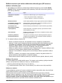
EC gas sensor calibration
Calibration of the measured gas
1. Before initiating a calibration process, the calibration parameters must be set by pressing on the
Modify button. The last calibration parameters are memorized, so this step can be ignored if the
correct parameters are already set.
Option Description
Calibration mode 2 types available, depending on the gas being measured:
• Direct value: Any gas
• In Air (default): For O
2
or O
3
Medium Select liquid or gas (direct calibration only)
Concentration unit type Partial, fraction or dissolved (dissolved is for calibration in a liquid only)
Concentration unit The list of available units depends on unit type selected above.
Liquid Select as appropriate, available when liquid has been selected in medium
(above).
Value Enter the gas concentration according to the value in the calibration media, when
direct value is used.
Hold during calibration On by default, this stops any output from the instrument during the calibration
process to avoid sending invalid information to any connected device.
2. Press OK to start calibration
• A calibration screen will be displayed showing current measurement data which is continually
refreshed.
• The value “% ideal current” is a percentage of the current against the ideal current for the
membrane type selected. If this percentage is not within the accepted range, an error message
is displayed and the calibration process fails. A warning message can be displayed when this
value is close to the boundaries, but when calibration can be accepted.
• The message is first displayed in the result box. The dialog box with the error message or the
warning is displayed when the finish button is pressed.
• The value “% last calibration” shows the ratio between the current measurement and the
previous sensor calibration.
• The value “% variation” indicates the variation during the last 3 measurements, which is the
stability of the measurements. A variation as low as possible is needed for a precise
calibration.
• The display shows the actual calibration parameters, and the actual readings (temperature,
barometer, current).
20
English
Sayfa yükleniyor...
Sayfa yükleniyor...
Sayfa yükleniyor...
Sayfa yükleniyor...
Sayfa yükleniyor...
Sayfa yükleniyor...
Sayfa yükleniyor...
Sayfa yükleniyor...
Sayfa yükleniyor...
Sayfa yükleniyor...
Sayfa yükleniyor...
Sayfa yükleniyor...
Sayfa yükleniyor...
Sayfa yükleniyor...
Sayfa yükleniyor...
Sayfa yükleniyor...
Sayfa yükleniyor...
Sayfa yükleniyor...
Sayfa yükleniyor...
Sayfa yükleniyor...
Sayfa yükleniyor...
Sayfa yükleniyor...
Sayfa yükleniyor...
Sayfa yükleniyor...
Sayfa yükleniyor...
Sayfa yükleniyor...
Sayfa yükleniyor...
Sayfa yükleniyor...
Sayfa yükleniyor...
Sayfa yükleniyor...
Sayfa yükleniyor...
Sayfa yükleniyor...
Sayfa yükleniyor...
Sayfa yükleniyor...
Sayfa yükleniyor...
Sayfa yükleniyor...
Sayfa yükleniyor...
Sayfa yükleniyor...
Sayfa yükleniyor...
Sayfa yükleniyor...
Sayfa yükleniyor...
Sayfa yükleniyor...
Sayfa yükleniyor...
Sayfa yükleniyor...
Sayfa yükleniyor...
Sayfa yükleniyor...
Sayfa yükleniyor...
Sayfa yükleniyor...
Sayfa yükleniyor...
Sayfa yükleniyor...
Sayfa yükleniyor...
Sayfa yükleniyor...
Sayfa yükleniyor...
Sayfa yükleniyor...
Sayfa yükleniyor...
Sayfa yükleniyor...
Sayfa yükleniyor...
Sayfa yükleniyor...
Sayfa yükleniyor...
Sayfa yükleniyor...
Sayfa yükleniyor...
Sayfa yükleniyor...
Sayfa yükleniyor...
Sayfa yükleniyor...
Sayfa yükleniyor...
Sayfa yükleniyor...
Sayfa yükleniyor...
Sayfa yükleniyor...
Sayfa yükleniyor...
Sayfa yükleniyor...
Sayfa yükleniyor...
Sayfa yükleniyor...
Sayfa yükleniyor...
Sayfa yükleniyor...
Sayfa yükleniyor...
Sayfa yükleniyor...
Sayfa yükleniyor...
Sayfa yükleniyor...
Sayfa yükleniyor...
Sayfa yükleniyor...
Sayfa yükleniyor...
Sayfa yükleniyor...
Sayfa yükleniyor...
Sayfa yükleniyor...
Sayfa yükleniyor...
Sayfa yükleniyor...
Sayfa yükleniyor...
Sayfa yükleniyor...
Sayfa yükleniyor...
Sayfa yükleniyor...
Sayfa yükleniyor...
Sayfa yükleniyor...
Sayfa yükleniyor...
Sayfa yükleniyor...
Sayfa yükleniyor...
Sayfa yükleniyor...
Sayfa yükleniyor...
Sayfa yükleniyor...
Sayfa yükleniyor...
Sayfa yükleniyor...
Sayfa yükleniyor...
Sayfa yükleniyor...
Sayfa yükleniyor...
Sayfa yükleniyor...
Sayfa yükleniyor...
Sayfa yükleniyor...
Sayfa yükleniyor...
Sayfa yükleniyor...
Sayfa yükleniyor...
Sayfa yükleniyor...
Sayfa yükleniyor...
Sayfa yükleniyor...
Sayfa yükleniyor...
Sayfa yükleniyor...
Sayfa yükleniyor...
Sayfa yükleniyor...
Sayfa yükleniyor...
Sayfa yükleniyor...
Sayfa yükleniyor...
Sayfa yükleniyor...
Sayfa yükleniyor...
Sayfa yükleniyor...
Sayfa yükleniyor...
Sayfa yükleniyor...
Sayfa yükleniyor...
Sayfa yükleniyor...
Sayfa yükleniyor...
Sayfa yükleniyor...
Sayfa yükleniyor...
Sayfa yükleniyor...
Sayfa yükleniyor...
Sayfa yükleniyor...
Sayfa yükleniyor...
Sayfa yükleniyor...
Sayfa yükleniyor...
Sayfa yükleniyor...
Sayfa yükleniyor...
Sayfa yükleniyor...
Sayfa yükleniyor...
Sayfa yükleniyor...
Sayfa yükleniyor...
Sayfa yükleniyor...
Sayfa yükleniyor...
Sayfa yükleniyor...
Sayfa yükleniyor...
Sayfa yükleniyor...
Sayfa yükleniyor...
Sayfa yükleniyor...
Sayfa yükleniyor...
Sayfa yükleniyor...
Sayfa yükleniyor...
Sayfa yükleniyor...
Sayfa yükleniyor...
Sayfa yükleniyor...
Sayfa yükleniyor...
Sayfa yükleniyor...
Sayfa yükleniyor...
Sayfa yükleniyor...
Sayfa yükleniyor...
Sayfa yükleniyor...
Sayfa yükleniyor...
Sayfa yükleniyor...
Sayfa yükleniyor...
Sayfa yükleniyor...
Sayfa yükleniyor...
Sayfa yükleniyor...
Sayfa yükleniyor...
Sayfa yükleniyor...
Sayfa yükleniyor...
Sayfa yükleniyor...
Sayfa yükleniyor...
Sayfa yükleniyor...
Sayfa yükleniyor...
Sayfa yükleniyor...
Sayfa yükleniyor...
Sayfa yükleniyor...
Sayfa yükleniyor...
Sayfa yükleniyor...
Sayfa yükleniyor...
Sayfa yükleniyor...
Sayfa yükleniyor...
Sayfa yükleniyor...
Sayfa yükleniyor...
Sayfa yükleniyor...
Sayfa yükleniyor...
Sayfa yükleniyor...
Sayfa yükleniyor...
Sayfa yükleniyor...
Sayfa yükleniyor...
Sayfa yükleniyor...
Sayfa yükleniyor...
Sayfa yükleniyor...
Sayfa yükleniyor...
Sayfa yükleniyor...
Sayfa yükleniyor...
Sayfa yükleniyor...
Sayfa yükleniyor...
Sayfa yükleniyor...
Sayfa yükleniyor...
Sayfa yükleniyor...
Sayfa yükleniyor...
Sayfa yükleniyor...
Sayfa yükleniyor...
Sayfa yükleniyor...
Sayfa yükleniyor...
Sayfa yükleniyor...
Sayfa yükleniyor...
Sayfa yükleniyor...
Sayfa yükleniyor...
Sayfa yükleniyor...
Sayfa yükleniyor...
Sayfa yükleniyor...
Sayfa yükleniyor...
Sayfa yükleniyor...
Sayfa yükleniyor...
Sayfa yükleniyor...
Sayfa yükleniyor...
Sayfa yükleniyor...
Sayfa yükleniyor...
Sayfa yükleniyor...
Sayfa yükleniyor...
Sayfa yükleniyor...
Sayfa yükleniyor...
Sayfa yükleniyor...
Sayfa yükleniyor...
Sayfa yükleniyor...
Sayfa yükleniyor...
Sayfa yükleniyor...
Sayfa yükleniyor...
Sayfa yükleniyor...
Sayfa yükleniyor...
Sayfa yükleniyor...
Sayfa yükleniyor...
Sayfa yükleniyor...
Sayfa yükleniyor...
Sayfa yükleniyor...
Sayfa yükleniyor...
Sayfa yükleniyor...
Sayfa yükleniyor...
Sayfa yükleniyor...
Sayfa yükleniyor...
Sayfa yükleniyor...
Sayfa yükleniyor...
Sayfa yükleniyor...
Sayfa yükleniyor...
Sayfa yükleniyor...
Sayfa yükleniyor...
Sayfa yükleniyor...
Sayfa yükleniyor...
Sayfa yükleniyor...
Sayfa yükleniyor...
Sayfa yükleniyor...
Sayfa yükleniyor...
Sayfa yükleniyor...
Sayfa yükleniyor...
Sayfa yükleniyor...
Sayfa yükleniyor...
Sayfa yükleniyor...
Sayfa yükleniyor...
Sayfa yükleniyor...
Sayfa yükleniyor...
Sayfa yükleniyor...
Sayfa yükleniyor...
Sayfa yükleniyor...
Sayfa yükleniyor...
Sayfa yükleniyor...
Sayfa yükleniyor...
Sayfa yükleniyor...
Sayfa yükleniyor...
Sayfa yükleniyor...
Sayfa yükleniyor...
Sayfa yükleniyor...
Sayfa yükleniyor...
Sayfa yükleniyor...
Sayfa yükleniyor...
Sayfa yükleniyor...
Sayfa yükleniyor...
Sayfa yükleniyor...
Sayfa yükleniyor...
Sayfa yükleniyor...
Sayfa yükleniyor...
Sayfa yükleniyor...
Sayfa yükleniyor...
Sayfa yükleniyor...
Sayfa yükleniyor...
Sayfa yükleniyor...
Sayfa yükleniyor...
Sayfa yükleniyor...
Sayfa yükleniyor...
Sayfa yükleniyor...
Sayfa yükleniyor...
Sayfa yükleniyor...
Sayfa yükleniyor...
Sayfa yükleniyor...
Sayfa yükleniyor...
Sayfa yükleniyor...
Sayfa yükleniyor...
Sayfa yükleniyor...
Sayfa yükleniyor...
Sayfa yükleniyor...
Sayfa yükleniyor...
Sayfa yükleniyor...
Sayfa yükleniyor...
Sayfa yükleniyor...
Sayfa yükleniyor...
Sayfa yükleniyor...
Sayfa yükleniyor...
Sayfa yükleniyor...
Sayfa yükleniyor...
Sayfa yükleniyor...
Sayfa yükleniyor...
Sayfa yükleniyor...
Sayfa yükleniyor...
Sayfa yükleniyor...
Sayfa yükleniyor...
Sayfa yükleniyor...
Sayfa yükleniyor...
Sayfa yükleniyor...
Sayfa yükleniyor...
Sayfa yükleniyor...
Sayfa yükleniyor...
Sayfa yükleniyor...
Sayfa yükleniyor...
Sayfa yükleniyor...
Sayfa yükleniyor...
Sayfa yükleniyor...
Sayfa yükleniyor...
Sayfa yükleniyor...
Sayfa yükleniyor...
Sayfa yükleniyor...
Sayfa yükleniyor...
Sayfa yükleniyor...
Sayfa yükleniyor...
Sayfa yükleniyor...
Sayfa yükleniyor...
Sayfa yükleniyor...
Sayfa yükleniyor...
Sayfa yükleniyor...
-
 1
1
-
 2
2
-
 3
3
-
 4
4
-
 5
5
-
 6
6
-
 7
7
-
 8
8
-
 9
9
-
 10
10
-
 11
11
-
 12
12
-
 13
13
-
 14
14
-
 15
15
-
 16
16
-
 17
17
-
 18
18
-
 19
19
-
 20
20
-
 21
21
-
 22
22
-
 23
23
-
 24
24
-
 25
25
-
 26
26
-
 27
27
-
 28
28
-
 29
29
-
 30
30
-
 31
31
-
 32
32
-
 33
33
-
 34
34
-
 35
35
-
 36
36
-
 37
37
-
 38
38
-
 39
39
-
 40
40
-
 41
41
-
 42
42
-
 43
43
-
 44
44
-
 45
45
-
 46
46
-
 47
47
-
 48
48
-
 49
49
-
 50
50
-
 51
51
-
 52
52
-
 53
53
-
 54
54
-
 55
55
-
 56
56
-
 57
57
-
 58
58
-
 59
59
-
 60
60
-
 61
61
-
 62
62
-
 63
63
-
 64
64
-
 65
65
-
 66
66
-
 67
67
-
 68
68
-
 69
69
-
 70
70
-
 71
71
-
 72
72
-
 73
73
-
 74
74
-
 75
75
-
 76
76
-
 77
77
-
 78
78
-
 79
79
-
 80
80
-
 81
81
-
 82
82
-
 83
83
-
 84
84
-
 85
85
-
 86
86
-
 87
87
-
 88
88
-
 89
89
-
 90
90
-
 91
91
-
 92
92
-
 93
93
-
 94
94
-
 95
95
-
 96
96
-
 97
97
-
 98
98
-
 99
99
-
 100
100
-
 101
101
-
 102
102
-
 103
103
-
 104
104
-
 105
105
-
 106
106
-
 107
107
-
 108
108
-
 109
109
-
 110
110
-
 111
111
-
 112
112
-
 113
113
-
 114
114
-
 115
115
-
 116
116
-
 117
117
-
 118
118
-
 119
119
-
 120
120
-
 121
121
-
 122
122
-
 123
123
-
 124
124
-
 125
125
-
 126
126
-
 127
127
-
 128
128
-
 129
129
-
 130
130
-
 131
131
-
 132
132
-
 133
133
-
 134
134
-
 135
135
-
 136
136
-
 137
137
-
 138
138
-
 139
139
-
 140
140
-
 141
141
-
 142
142
-
 143
143
-
 144
144
-
 145
145
-
 146
146
-
 147
147
-
 148
148
-
 149
149
-
 150
150
-
 151
151
-
 152
152
-
 153
153
-
 154
154
-
 155
155
-
 156
156
-
 157
157
-
 158
158
-
 159
159
-
 160
160
-
 161
161
-
 162
162
-
 163
163
-
 164
164
-
 165
165
-
 166
166
-
 167
167
-
 168
168
-
 169
169
-
 170
170
-
 171
171
-
 172
172
-
 173
173
-
 174
174
-
 175
175
-
 176
176
-
 177
177
-
 178
178
-
 179
179
-
 180
180
-
 181
181
-
 182
182
-
 183
183
-
 184
184
-
 185
185
-
 186
186
-
 187
187
-
 188
188
-
 189
189
-
 190
190
-
 191
191
-
 192
192
-
 193
193
-
 194
194
-
 195
195
-
 196
196
-
 197
197
-
 198
198
-
 199
199
-
 200
200
-
 201
201
-
 202
202
-
 203
203
-
 204
204
-
 205
205
-
 206
206
-
 207
207
-
 208
208
-
 209
209
-
 210
210
-
 211
211
-
 212
212
-
 213
213
-
 214
214
-
 215
215
-
 216
216
-
 217
217
-
 218
218
-
 219
219
-
 220
220
-
 221
221
-
 222
222
-
 223
223
-
 224
224
-
 225
225
-
 226
226
-
 227
227
-
 228
228
-
 229
229
-
 230
230
-
 231
231
-
 232
232
-
 233
233
-
 234
234
-
 235
235
-
 236
236
-
 237
237
-
 238
238
-
 239
239
-
 240
240
-
 241
241
-
 242
242
-
 243
243
-
 244
244
-
 245
245
-
 246
246
-
 247
247
-
 248
248
-
 249
249
-
 250
250
-
 251
251
-
 252
252
-
 253
253
-
 254
254
-
 255
255
-
 256
256
-
 257
257
-
 258
258
-
 259
259
-
 260
260
-
 261
261
-
 262
262
-
 263
263
-
 264
264
-
 265
265
-
 266
266
-
 267
267
-
 268
268
-
 269
269
-
 270
270
-
 271
271
-
 272
272
-
 273
273
-
 274
274
-
 275
275
-
 276
276
-
 277
277
-
 278
278
-
 279
279
-
 280
280
-
 281
281
-
 282
282
-
 283
283
-
 284
284
-
 285
285
-
 286
286
-
 287
287
-
 288
288
-
 289
289
-
 290
290
-
 291
291
-
 292
292
-
 293
293
-
 294
294
-
 295
295
-
 296
296
-
 297
297
-
 298
298
-
 299
299
-
 300
300
-
 301
301
-
 302
302
-
 303
303
-
 304
304
-
 305
305
-
 306
306
-
 307
307
-
 308
308
-
 309
309
-
 310
310
-
 311
311
-
 312
312
-
 313
313
-
 314
314
-
 315
315
-
 316
316
-
 317
317
-
 318
318
-
 319
319
-
 320
320
-
 321
321
-
 322
322
-
 323
323
-
 324
324
-
 325
325
-
 326
326
-
 327
327
-
 328
328
-
 329
329
-
 330
330
-
 331
331
-
 332
332
-
 333
333
-
 334
334
-
 335
335
-
 336
336
-
 337
337
-
 338
338
-
 339
339
-
 340
340
-
 341
341
-
 342
342
-
 343
343
-
 344
344
-
 345
345
-
 346
346
-
 347
347
-
 348
348
-
 349
349
-
 350
350
-
 351
351
-
 352
352
-
 353
353
-
 354
354
-
 355
355
-
 356
356
-
 357
357
-
 358
358


diğer dillerde
- español: Hach ORBISPHERE 410
- français: Hach ORBISPHERE 410
- italiano: Hach ORBISPHERE 410
- svenska: Hach ORBISPHERE 410
- čeština: Hach ORBISPHERE 410
- polski: Hach ORBISPHERE 410
- Deutsch: Hach ORBISPHERE 410
- English: Hach ORBISPHERE 410
- dansk: Hach ORBISPHERE 410
- русский: Hach ORBISPHERE 410
- Nederlands: Hach ORBISPHERE 410
- română: Hach ORBISPHERE 410
İlgili makaleler
-
 Hach ORBISPHERE 510 Basic User Manual
-
 Hach 51 Series Kullanım kılavuzu
-
 Hach ORBISPHERE K-M1100 Basic User Manual
-
 Hach Polymetron 9582sc Basic User Manual
-
 Hach polymetron 9240 Basic User Manual
-
 Hach Polymentron 9500 Basic User Manual
-
 Hach 9586sc Basic User Manual
-
 Hach ORBISPHERE 31 series Basic User Manual
-
 Hach orbisphere C1100 Kullanım kılavuzu
-
Hach SC200 Basic User Manual


Diğer belgeler
-
 Brooks CMX0 / CMX1 / CMX2 / CMX3 Kullanma talimatları
-
GGM Gastro SKSF700 El kitabı
-
Sera CO2-Start Information For Use
-
Rehau Base 24 V Yükleme Rehberi
-
 Renfert EASY view 2400XX00 | UV Filter Color Calibration Kullanım kılavuzu
-
FläktGroup CAIRplus Installation and Maintenance Manual
-
Rehau 13280001001 Yükleme Rehberi
-
 STEGO STO 011 Kullanici rehberi
-
STEGO Type STO-STS 011 Kullanım kılavuzu
-
Rehau NEA SMART 2.0 Yükleme Rehberi


