
GRUNDFOS INSTRUCTIONS
Level transmitters
Installation and operating instructions
Types S, W, E
Other languages
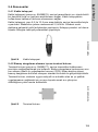
net.grundfos.com/qr/i/99545030
Grundfos
Product
Center

2

Table of contents
3
Level transmitters
English (GB)
Installation and operating instructions . . . . . . . . . . . . . . . . . . . . . . . . . . . . . . . . 4
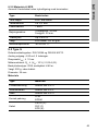
Deutsch (DE)
Montage- und Betriebsanleitung . . . . . . . . . . . . . . . . . . . . . . . . . . . . . . . . . . . 25
Dansk (DK)
Monterings- og driftsinstruktion . . . . . . . . . . . . . . . . . . . . . . . . . . . . . . . . . . . . 46
Español (ES)
Instrucciones de instalación y funcionamiento . . . . . . . . . . . . . . . . . . . . . . . . 67
Français (FR)
Notice d'installation et de fonctionnement . . . . . . . . . . . . . . . . . . . . . . . . . . . . 88
Lietuviškai (LT)
Įrengimo ir naudojimo instrukcija. . . . . . . . . . . . . . . . . . . . . . . . . . . . . . . . . . 109
Polski (PL)
Instrukcja montażu i eksploatacji. . . . . . . . . . . . . . . . . . . . . . . . . . . . . . . . . . 129
Türkçe (TR)
Montaj ve kullanım kılavuzu . . . . . . . . . . . . . . . . . . . . . . . . . . . . . . . . . . . . . 150
中文 (CN)
安装和使用说明书 . . . . . . . . . . . . . . . . . . . . . . . . . . . . . . . . . . . . . . . . . . . . . 172
ﺔﻳﺑﺭﻌﻟﺍ (AR)
ﻝﻳﻐﺷﺗﻟﺍ ﻭ ﺏﻳﻛﺭﺗﻟﺍ ﺕﺎﻣﻳﻠﻌﺗ . . . . . . . . . . . . . . . . . . . . . . . . . . . . . . . . . . . . . 211
Declaration of conformity. . . . . . . . . . . . . . . . . . . . . . . . . . . . . . . . . . . . . . . . .212

English (GB)
4
English (GB) Installation and operating instructions
CONTENTS
Page
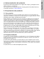
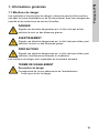
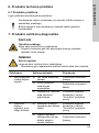
1. General information
5
1.1 Hazard statements
5
1.2 Notes
6
2. Receiving the product
6
3. Installing the product
7
3.1 Wiring diagram
8
4. Storing the product
10
5. Product introduction
10
5.1 Intended use
10
5.2 Pumped liquid
10
5.3 Identification
11
5.4 Accessories
13
6. Servicing the product
14
6.1 Maintaining the product
14
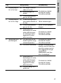
7. Fault finding the product
14
8. Technical data
17
8.1 Dimensions
17
8.2 Materials
20
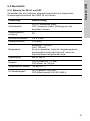
8.3 Type S
21
8.4 Type E
22
8.5 Type W
23
9. Disposal
24
Read this document before installing the product. Installation and
operation must comply with local regulations and accepted codes
of good practice.

English (GB)
5
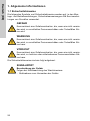
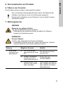
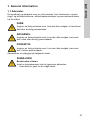
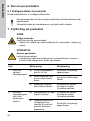
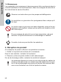
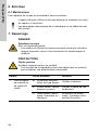
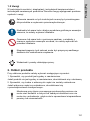
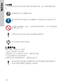
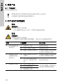
1. General information
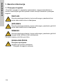
1.1 Hazard statements
The symbols and hazard statements below may appear in Grundfos
installation and operating instructions, safety instructions and service
instructions.
The hazard statements are structured in the following way:
DANGER
Indicates a hazardous situation which, if not avoided, will result in
death or serious personal injury.
WARNING
Indicates a hazardous situation which, if not avoided, could result
in death or serious personal injury.
CAUTION
Indicates a hazardous situation which, if not avoided, could result
in minor or moderate personal injury.
SIGNAL WORD
Description of hazard
Consequence of ignoring the warning.
- Action to avoid the hazard.

English (GB)
6
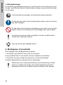
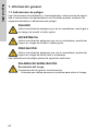
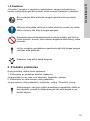
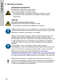
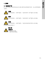
1.2 Notes
The symbols and notes below may appear in Grundfos installation and
operating instructions, safety instructions and service instructions.
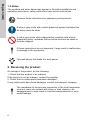
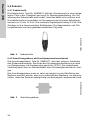
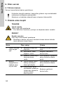
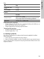
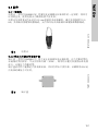
2. Receiving the product
On receipt of the product, do the following:
1. Check that the product is as ordered.
If the product is not as ordered, contact the supplier.
2. Check that no visible parts have been damaged.
If any visible parts have been damaged, contact the transport company.
Observe these instructions for explosion-proof products.
A blue or grey circle with a white graphical symbol indicates that
an action must be taken.
A red or grey circle with a diagonal bar, possibly with a black
graphical symbol, indicates that an action must not be taken or
must be stopped.
If these instructions are not observed, it may result in malfunction
or damage to the equipment.
Tips and advice that make the work easier.
The membrane at the process connection of the level transmitter
must not come into contact with sharp or hard objects or be
damaged since it may result in incorrect measurements or even
media leakage.

English (GB)
7
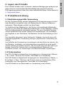
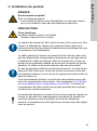
3. Installing the product
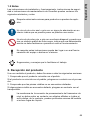
DANGER
Explosive environment
Death or serious personal injury
- The products in these installation instructions are not intended
for use in potentially explosive areas.
CAUTION
Electric shock
Minor or moderate personal injury
- Install the product in a currentless condition.
The level transmitter must be grounded. To prevent electrolysis,
the shielding of the level transmitter must be set to the same
potential as the products usually found in the medium, such as
pumps and agitators.
The special cable for the level transmitter must be fitted so that the
pressure compensation in the cable assembly is not crushed. The
cable end must terminate in a dry room or in a suitable terminal
case so that no moisture can get through. In addition, the cable
must not be routed through damp conditions.
For variations in media, a guide tube must be used to prevent
measuring errors in flow caused by sideways movement and by
hitting the level transmitter against the walls of the container.
We recommend using a terminal case with a pressure
compensation element. See section 5.4.2 Terminal case with
pressure compensation element. The terminal case must be
mounted as close as possible to the surface of the medium while
still outside the medium.
The membrane at the process connection of the level transmitter
must not be damaged, otherwise it may result in incorrect
measurements or even media leakage. The membrane must not
come into contact with sharp or hard objects.

English (GB)
8
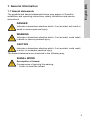
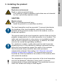
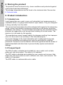
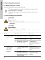
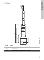
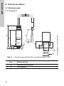
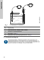
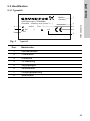
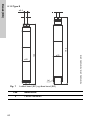
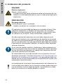
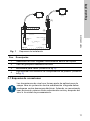
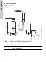
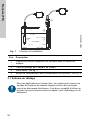
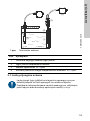
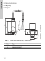
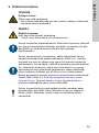
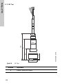
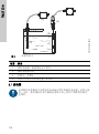
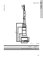
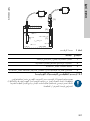
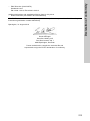
Fig. 1 Installation principal
3.1 Wiring diagram
TM07 3095 4618
Pos. Description
1 Level transmitter, hanging vertically in the medium.
2 Guide tube for level transmitter.
3 Cable clamp. See fig. 4
4 Terminal case with pressure compensation element. See fig. 5
Level transmitters in free-field applications without integrated
overvoltage protection must be protected against electrical
discharge. In addition, we recommend using external overvoltage
protection upstream and downstream of the display or processing
unit.
(4)
(3)
(2)
(1)
(1)
(4)

English (GB)
9
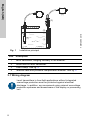
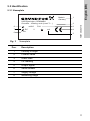
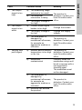
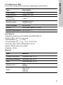
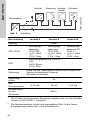
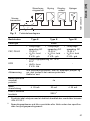
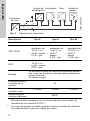
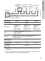
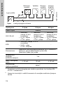
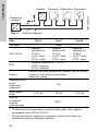
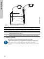
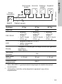
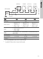
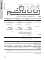
Fig. 2 Wiring diagram
1
The product must be equipped with an electrical circuit that meets the
requirements of EN 61010-1.
2
The voltage peaks must not exceed or fall below the specified supply
voltage value.
TM07 3094 4618
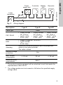
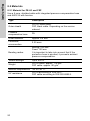
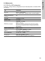
Description Type S Type E Type W
Cable type Cable
FEP, PE-LD
• Supply voltage
DC 10-30 V
•U
B
/S+: white
0 V/S-: grey
• Supply voltage
DC 10-30 V
•U
B
/S+
2
: white
0 V/S-: grey
• Supply voltage
DC 12-30 V
•U
B
/S+
2
: white
0 V/S-: grey
EPR
• Supply voltage DC 10 to 30 V
•U
B
/S+: brown
0 V/S-: blue
-
Shielding
Ground all connected products such as pumps and
valves to the same potential.
The cable is black.
Reverse voltage
protection
Yes
Max. current
consumption
≤ 25 mA 30 mA ≤ 25 mA
Electrical circuit
requirements
SELV
1
Level
transmitter
Controller Display
unit
Power
supply unit
Recorder

English (GB)
10
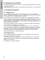
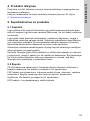
4. Storing the product
The products must be stored in dry, clean conditions and protected against
external and mechanical damage.
The storage temperatures can be found in the technical data. See section
8. Technical data.
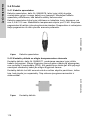
5. Product introduction
5.1 Intended use
Level transmitters are used to carry out hydrostatic level measurements in
ventilated tanks or to gauge water levels in open waters. They are designed
to hang vertically from the cable.
The correct level transmitter should be selected with regard to the measuring
range, version and specific measuring conditions on site before mounting,
installation and startup. The specifications provided by the manufacturer are
intended as suggestions only, except those relating to the test series. The
decision is to be made by the operator.
The manufacturer cannot accept liability for damage resulting from improper
use or in the event of use contrary to the intended purpose.
To prevent damage to the level transmitter and to safeguard its process,
mounting, installation and startup must only be performed by qualified
personnel. Personnel must be familiar with local regulations and be aware of
applied standards and directives to prevent bodily injuries and material
damage.
5.2 Pumped liquid
The PE-LD cable is shielded and suitable for use in water such as lake,
water well, and mine water. The cable is UV-resistant.
The FEP cable is shielded and suitable for use in water such as sea, lake,
water well, and mine water as well in different oils, fuels, and solvents. The
cable is UV-resistant.
The EPR cable is a submersible motor cable.

English (GB)
11
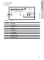
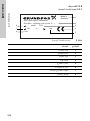
5.3 Identification
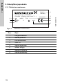
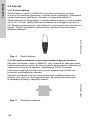
5.3.1 Nameplate
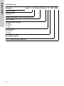
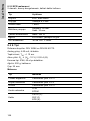
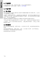
Fig. 3 Nameplate
TM07 3048 4718
Pos. Description
1 Country of origin
2 Product name
3 Order code
4CE marking
5 Output signal
6 Serial number
7 Supply voltage
8 Measuring range
Made in
Germany
8850 Bjerringbro, DENMARK
Grundfos - ordering code (Level Tr...)
mH20 P/N
DC V
mA
F-No.
1
2
3
4
5
6
7
8

English (GB)
12
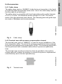
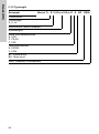
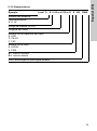
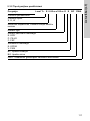
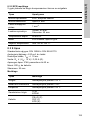
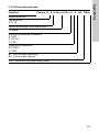
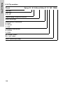
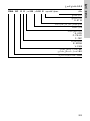
5.3.2 Type key
Example Level Tr. E 0-50 m c100 m E E BC DWA
Product name
Product type:
S, E, W
Measuring range, metre of water column
Cable length
Cable surface material
E: EPR
P: PE-LD
F: FEP
Seal material
E: EPDM
V: FKM
BC: Bottom closed
BO: Bottom open
DWA: Drinking water approval

English (GB)
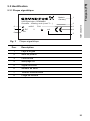
13
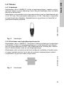
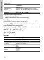
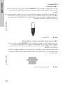
5.4 Accessories
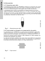
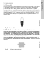
5.4.1 Cable clamp
The cable clamp, part no. 99488578, holds the level transmitter in the liquid
at a defined depth and provides strain relief. Use of the cable clamp ensures
that the cable is not deformed.
The cable clamp is compatible with level transmitters with a cable diameter
of 5.5 to 10.5 mm. The maximum tensile strength is 2.5 kN. The case is
made of hot-dip galvanised steel sheets. The clamping jaws and guide clips
are made of fiberglass-reinforced polyamide.
Fig. 4 Cable clamp
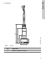
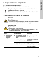
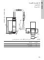
5.4.2 Terminal case with pressure compensation element
The terminal case, part no. 99488577, is used for secure installation of the
level transmitter cable. The end of the pressure equalisation hose is always
protected from deposits and condensation (IP65). The remaining distribution
can be performed with a standard cable without a pressure equalisation
hose.
The terminal case must be mounted as close as possible to the medium
surface while still outside the medium to ensure the system is implemented
cost-effectively and in the best possible way.
Fig. 5 Terminal case
TM07 3006 4418TM07 3005 4418

English (GB)
14
6. Servicing the product
6.1 Maintaining the product
The level transmitters are maintenance-free.
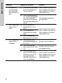
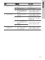
7. Fault finding the product
The cleaning agent used must not attack the material on the
transmitter body or the seals.
Mechanical damage to the membrane and the cable must be
avoided.
DANGER
Toxic material
Death or serious personal injury
- Medium residuals may damage humans, the environment and
equipment.
CAUTION
Sharp objects
Minor or moderate personal injury
- Irreparable damage occurs if the membrane comes into contact
with sharp or hard objects.
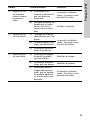
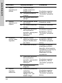
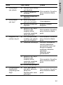
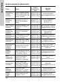
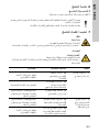
Fault Possible cause Remedy
1. No measuring
and/or output
signal.
a) The supply voltage is
too low
Check the supply
voltage.
b) Open circuit, there is an
incorrect connection.
Check the connecting
cable.
c) Mechanical, thermal or
chemical damage.
The product is
defective. Contact your
local Grundfos sales
office.
2. Constant
output signal
even with
changes in
pressure.
a) The measuring system
is destroyed by excess
pressure.
The product is
defective. Contact your
local Grundfos sales
office.
b) The output signal is
distorted as a result of
excess pressure due to
current limiting.
Check the supply
voltage.

English (GB)
15
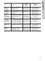
3. The output
signal is too
high.
a) The measuring range
selected is too small.
The product is
defective. Contact your
local Grundfos sales
office.
b) The electrical
connection is faulty.
c) The supply voltage is
too high.
4. The output
signal is too
weak.
a) Current output signal
burden is too high.
Change the burden.
b) The supply voltage is
too low.
Change the supply
voltage.
c) The membrane is
damaged by
mechanical influences,
for example an
aggressive medium or
corrosion.
The product is
defective. Contact your
local Grundfos sales
office.
5. Varying zero
point signal.
a) Medium and/or ambient
temperature is too high
or too low
The product is
defective. Contact your
local Grundfos sales
office.
b) Membrane
contaminated
Carefully clean the
membrane using a soft
brush or sponge with a
non-aggressive
cleaning agent.
The membrane must
not be damaged.
c) The membrane is
damaged by
mechanical influences,
for example an
aggressive medium or
corrosion.
The product is
defective. Contact your
local Grundfos sales
office.
d) Moisture has entered
the product.
Fault Possible cause Remedy

English (GB)
16
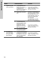
6. Characteristic
line of the
output signal is
not linear.
a) The product is altered
by inadmissible
operating conditions
such as excess
pressure.
The product is
defective. Contact your
local Grundfos sales
office.
Fault Possible cause Remedy

English (GB)
17
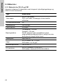
8. Technical data
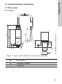
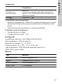
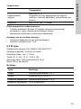
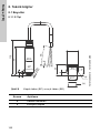
8.1 Dimensions
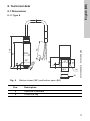
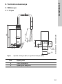
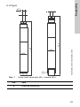
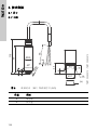
8.1.1 Type S
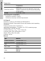
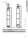
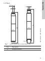
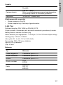
Fig. 6 Bottom closed (BC) and bottom open (BO)
TM07 3089 5018 - TM07 3090 4918
Pos. Description
a Sensitive membrane
b Protective cap
12
Ø25
60
°
8
3
Ø
5x
93
65
4
116
Ø17
7
24
40
°
19
(b)
(a)

English (GB)
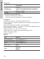
18
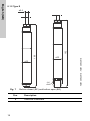
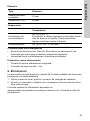
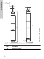
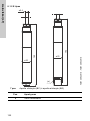
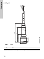
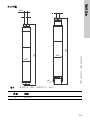
8.1.2 Type E
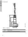
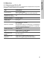
Fig. 7 Bottom closed (BC) and bottom open (BO)
TM07 3092 4918 - TM07 3093 4918
Pos. Description
a Sensitive membrane
180
ø8.4
ø25
(a)
192
ø25

English (GB)
19
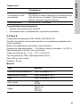
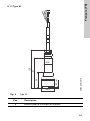
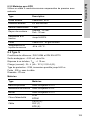
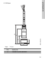
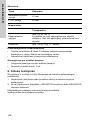
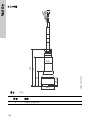
8.1.3 Type W
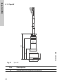
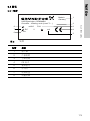
Fig. 8 Type W
TM07 3091 4918
Pos. Description
a Measurement to the surface of sensor
Ø41
Ø25
2.5 (a)
120
97
50

English (GB)
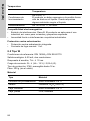
20
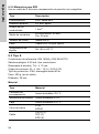
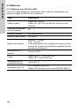
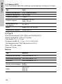
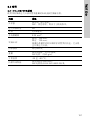
8.2 Materials
8.2.1 Material for PE-LD and FEP
Use a 6-core, shielded cable with integrated pressure compensation hose
and AWG 24 with ferrules.
Type Description
Outer sheath
PE-LD, black cable.
FEP, black cable. Depending on the version
ordered.
Pressure
compensation hose
PA
Outer diameter Approx. 8.4 mm.
Conductor
cross-section
0.25 mm
2
.
Bending radius:
Moving: 160 mm.
Fixed: 120 mm.
It is important to take into account that if the
protective hose is pinched, it prevents ambient
pressure compensation.
Tensile strength Up to 400 N.
Weight
PE-LD cable: approx. 115 g/m.
FEP cable: approx. 90 g/m.
Medium temperatures -20 to +60 °C.
UV resistance
PE-LD according to VDE 0207.
FEP cable according to DIN ISO 4892-2.
Sayfa yükleniyor...
Sayfa yükleniyor...
Sayfa yükleniyor...
Sayfa yükleniyor...
Sayfa yükleniyor...
Sayfa yükleniyor...
Sayfa yükleniyor...
Sayfa yükleniyor...
Sayfa yükleniyor...
Sayfa yükleniyor...
Sayfa yükleniyor...
Sayfa yükleniyor...
Sayfa yükleniyor...
Sayfa yükleniyor...
Sayfa yükleniyor...
Sayfa yükleniyor...
Sayfa yükleniyor...
Sayfa yükleniyor...
Sayfa yükleniyor...
Sayfa yükleniyor...
Sayfa yükleniyor...
Sayfa yükleniyor...
Sayfa yükleniyor...
Sayfa yükleniyor...
Sayfa yükleniyor...
Sayfa yükleniyor...
Sayfa yükleniyor...
Sayfa yükleniyor...
Sayfa yükleniyor...
Sayfa yükleniyor...
Sayfa yükleniyor...
Sayfa yükleniyor...
Sayfa yükleniyor...
Sayfa yükleniyor...
Sayfa yükleniyor...
Sayfa yükleniyor...
Sayfa yükleniyor...
Sayfa yükleniyor...
Sayfa yükleniyor...
Sayfa yükleniyor...
Sayfa yükleniyor...
Sayfa yükleniyor...
Sayfa yükleniyor...
Sayfa yükleniyor...
Sayfa yükleniyor...
Sayfa yükleniyor...
Sayfa yükleniyor...
Sayfa yükleniyor...
Sayfa yükleniyor...
Sayfa yükleniyor...
Sayfa yükleniyor...
Sayfa yükleniyor...
Sayfa yükleniyor...
Sayfa yükleniyor...
Sayfa yükleniyor...
Sayfa yükleniyor...
Sayfa yükleniyor...
Sayfa yükleniyor...
Sayfa yükleniyor...
Sayfa yükleniyor...
Sayfa yükleniyor...
Sayfa yükleniyor...
Sayfa yükleniyor...
Sayfa yükleniyor...
Sayfa yükleniyor...
Sayfa yükleniyor...
Sayfa yükleniyor...
Sayfa yükleniyor...
Sayfa yükleniyor...
Sayfa yükleniyor...
Sayfa yükleniyor...
Sayfa yükleniyor...
Sayfa yükleniyor...
Sayfa yükleniyor...
Sayfa yükleniyor...
Sayfa yükleniyor...
Sayfa yükleniyor...
Sayfa yükleniyor...
Sayfa yükleniyor...
Sayfa yükleniyor...
Sayfa yükleniyor...
Sayfa yükleniyor...
Sayfa yükleniyor...
Sayfa yükleniyor...
Sayfa yükleniyor...
Sayfa yükleniyor...
Sayfa yükleniyor...
Sayfa yükleniyor...
Sayfa yükleniyor...
Sayfa yükleniyor...
Sayfa yükleniyor...
Sayfa yükleniyor...
Sayfa yükleniyor...
Sayfa yükleniyor...
Sayfa yükleniyor...
Sayfa yükleniyor...
Sayfa yükleniyor...
Sayfa yükleniyor...
Sayfa yükleniyor...
Sayfa yükleniyor...
Sayfa yükleniyor...
Sayfa yükleniyor...
Sayfa yükleniyor...
Sayfa yükleniyor...
Sayfa yükleniyor...
Sayfa yükleniyor...
Sayfa yükleniyor...
Sayfa yükleniyor...
Sayfa yükleniyor...
Sayfa yükleniyor...
Sayfa yükleniyor...
Sayfa yükleniyor...
Sayfa yükleniyor...
Sayfa yükleniyor...
Sayfa yükleniyor...
Sayfa yükleniyor...
Sayfa yükleniyor...
Sayfa yükleniyor...
Sayfa yükleniyor...
Sayfa yükleniyor...
Sayfa yükleniyor...
Sayfa yükleniyor...
Sayfa yükleniyor...
Sayfa yükleniyor...
Sayfa yükleniyor...
Sayfa yükleniyor...
Sayfa yükleniyor...
Sayfa yükleniyor...
Sayfa yükleniyor...
Sayfa yükleniyor...
Sayfa yükleniyor...
Sayfa yükleniyor...
Sayfa yükleniyor...
Sayfa yükleniyor...
Sayfa yükleniyor...
Sayfa yükleniyor...
Sayfa yükleniyor...
Sayfa yükleniyor...
Sayfa yükleniyor...
Sayfa yükleniyor...
Sayfa yükleniyor...
Sayfa yükleniyor...
Sayfa yükleniyor...
Sayfa yükleniyor...
Sayfa yükleniyor...
Sayfa yükleniyor...
Sayfa yükleniyor...
Sayfa yükleniyor...
Sayfa yükleniyor...
Sayfa yükleniyor...
Sayfa yükleniyor...
Sayfa yükleniyor...
Sayfa yükleniyor...
Sayfa yükleniyor...
Sayfa yükleniyor...
Sayfa yükleniyor...
Sayfa yükleniyor...
Sayfa yükleniyor...
Sayfa yükleniyor...
Sayfa yükleniyor...
Sayfa yükleniyor...
Sayfa yükleniyor...
Sayfa yükleniyor...
Sayfa yükleniyor...
Sayfa yükleniyor...
Sayfa yükleniyor...
Sayfa yükleniyor...
Sayfa yükleniyor...
Sayfa yükleniyor...
Sayfa yükleniyor...
Sayfa yükleniyor...
Sayfa yükleniyor...
Sayfa yükleniyor...
Sayfa yükleniyor...
Sayfa yükleniyor...
Sayfa yükleniyor...
Sayfa yükleniyor...
Sayfa yükleniyor...
Sayfa yükleniyor...
Sayfa yükleniyor...
Sayfa yükleniyor...
Sayfa yükleniyor...
Sayfa yükleniyor...
Sayfa yükleniyor...
Sayfa yükleniyor...
Sayfa yükleniyor...
Sayfa yükleniyor...
Sayfa yükleniyor...
Sayfa yükleniyor...
Sayfa yükleniyor...
Sayfa yükleniyor...
Sayfa yükleniyor...
Sayfa yükleniyor...
Sayfa yükleniyor...
Sayfa yükleniyor...
Sayfa yükleniyor...
-
 1
1
-
 2
2
-
 3
3
-
 4
4
-
 5
5
-
 6
6
-
 7
7
-
 8
8
-
 9
9
-
 10
10
-
 11
11
-
 12
12
-
 13
13
-
 14
14
-
 15
15
-
 16
16
-
 17
17
-
 18
18
-
 19
19
-
 20
20
-
 21
21
-
 22
22
-
 23
23
-
 24
24
-
 25
25
-
 26
26
-
 27
27
-
 28
28
-
 29
29
-
 30
30
-
 31
31
-
 32
32
-
 33
33
-
 34
34
-
 35
35
-
 36
36
-
 37
37
-
 38
38
-
 39
39
-
 40
40
-
 41
41
-
 42
42
-
 43
43
-
 44
44
-
 45
45
-
 46
46
-
 47
47
-
 48
48
-
 49
49
-
 50
50
-
 51
51
-
 52
52
-
 53
53
-
 54
54
-
 55
55
-
 56
56
-
 57
57
-
 58
58
-
 59
59
-
 60
60
-
 61
61
-
 62
62
-
 63
63
-
 64
64
-
 65
65
-
 66
66
-
 67
67
-
 68
68
-
 69
69
-
 70
70
-
 71
71
-
 72
72
-
 73
73
-
 74
74
-
 75
75
-
 76
76
-
 77
77
-
 78
78
-
 79
79
-
 80
80
-
 81
81
-
 82
82
-
 83
83
-
 84
84
-
 85
85
-
 86
86
-
 87
87
-
 88
88
-
 89
89
-
 90
90
-
 91
91
-
 92
92
-
 93
93
-
 94
94
-
 95
95
-
 96
96
-
 97
97
-
 98
98
-
 99
99
-
 100
100
-
 101
101
-
 102
102
-
 103
103
-
 104
104
-
 105
105
-
 106
106
-
 107
107
-
 108
108
-
 109
109
-
 110
110
-
 111
111
-
 112
112
-
 113
113
-
 114
114
-
 115
115
-
 116
116
-
 117
117
-
 118
118
-
 119
119
-
 120
120
-
 121
121
-
 122
122
-
 123
123
-
 124
124
-
 125
125
-
 126
126
-
 127
127
-
 128
128
-
 129
129
-
 130
130
-
 131
131
-
 132
132
-
 133
133
-
 134
134
-
 135
135
-
 136
136
-
 137
137
-
 138
138
-
 139
139
-
 140
140
-
 141
141
-
 142
142
-
 143
143
-
 144
144
-
 145
145
-
 146
146
-
 147
147
-
 148
148
-
 149
149
-
 150
150
-
 151
151
-
 152
152
-
 153
153
-
 154
154
-
 155
155
-
 156
156
-
 157
157
-
 158
158
-
 159
159
-
 160
160
-
 161
161
-
 162
162
-
 163
163
-
 164
164
-
 165
165
-
 166
166
-
 167
167
-
 168
168
-
 169
169
-
 170
170
-
 171
171
-
 172
172
-
 173
173
-
 174
174
-
 175
175
-
 176
176
-
 177
177
-
 178
178
-
 179
179
-
 180
180
-
 181
181
-
 182
182
-
 183
183
-
 184
184
-
 185
185
-
 186
186
-
 187
187
-
 188
188
-
 189
189
-
 190
190
-
 191
191
-
 192
192
-
 193
193
-
 194
194
-
 195
195
-
 196
196
-
 197
197
-
 198
198
-
 199
199
-
 200
200
-
 201
201
-
 202
202
-
 203
203
-
 204
204
-
 205
205
-
 206
206
-
 207
207
-
 208
208
-
 209
209
-
 210
210
-
 211
211
-
 212
212
-
 213
213
-
 214
214
-
 215
215
-
 216
216


Grundfos E Series Installation And Operating Instructions Manual
- Tip
- Installation And Operating Instructions Manual
diğer dillerde
- español: Grundfos E Series
- français: Grundfos E Series
- polski: Grundfos E Series
- Deutsch: Grundfos E Series
- English: Grundfos E Series
- dansk: Grundfos E Series
İlgili makaleler
-
Grundfos Vaccuperm VGS -143 Installation And Operating Instructions Manual
-
-
-
Grundfos Conex DIA-1 Installation And Operating Instructions Manual
-
-
-
-
-
-