
7G3, 7U2*, 7U10, 7U15*, 7U25, 7U26, 7U27,
7U30*, 7U32*, 7U33, 7U42, 7U43, 7U46
Gebrauchsanweisung ................................................................ 3
Instructions for use .................................................................... 9
Instructions d'utilisation ............................................................. 15
Istruzioni per l’uso ..................................................................... 22
Instrucciones de uso ................................................................. 29
Manual de utilização .................................................................. 35
Gebruiksaanwijzing ................................................................... 42
Bruksanvisning ......................................................................... 48
Brugsanvisning ......................................................................... 54
Bruksanvisning ......................................................................... 60
Instrukcja użytkowania ............................................................... 66
Használati utasítás .................................................................... 73
Návod k použití ......................................................................... 79
Kullanma talimatı ....................................................................... 85
Οδηγίες χρήσης ....................................................................... 91
Руководство по применению .................................................... 98

1 2
2

1 Vorwort Deutsch
INFORMATION
Datum der letzten Aktualisierung: 2021-09-23
►Lesen Sie dieses Dokument vor Gebrauch des Produkts aufmerksam
durch und beachten Sie die Sicherheitshinweise.
►Weisen Sie den Benutzer in den sicheren Gebrauch des Produkts ein.
►Wenden Sie sich an den Hersteller, wenn Sie Fragen zum Produkt ha
ben oder Probleme auftreten.
►Melden Sie jedes schwerwiegende Vorkommnis im Zusammenhang
mit dem Produkt, insbesondere eine Verschlechterung des Gesund
heitszustands, dem Hersteller und der zuständigen Behörde Ihres Lan
des.
►Bewahren Sie dieses Dokument auf.
Die Gebrauchsanweisung gibt Ihnen wichtige Informationen zur Verarbei
tung der Unterschenkel-Beinschienen 7G3, 7U2*, 7U10, 7U15*, 7U25,
7U26, 7U27, 7U30*, 7U32*, 7U33, 7U42, 7U43 und 7U46.
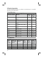
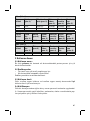
2 Produktbeschreibung
Die Unterschenkel-Beinschienen sind für die Herstellung einer Unterschen
kelprothese mit einer Oberschenkelhülse geeignet.
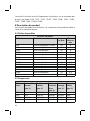
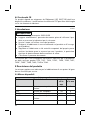
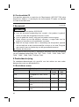
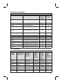
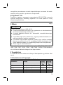
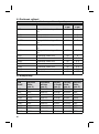
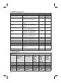
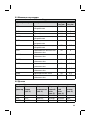
2.1 Verfügbare Größen
Unterschenkel-Beinschienen
Kennzeichen Material Breite in
mm
Dicke in
mm
7G3 Orthopädiestahl, vernickelt 23 5
7U2* Orthopädiestahl 24 3
7U10 Orthopädiestahl 24 3
7U15* Orthopädiestahl, vernickelt 24 3
7U25 Orthopädiestahl, vernickelt 24 3
7U26 Orthopädiestahl, vernickelt 22 2.5
7U27 Edelstahl rostfrei 20 3
7U30* Edelstahl rostfrei 20 2.3
7U32* Edelstahl rostfrei 20 2.3
7U33 Edelstahl rostfrei 20 2.3
7U42 Edelstahl rostfrei 20 2.3
7U43 Orthopädiestahl 22 2.5
3

Unterschenkel-Beinschienen
Kennzeichen Material Breite in
mm
Dicke in
mm
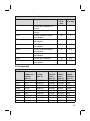
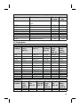
7U46 Edelstahl rostfrei 20 1.75
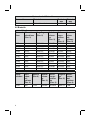
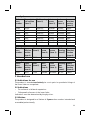
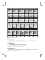
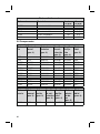
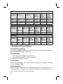
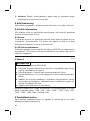
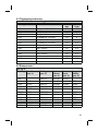
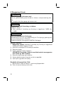
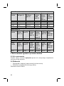
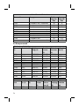
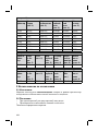
2.2 Bauteile
(siehe Abb.1)
Kennzei
chen
Oberschen
kelschiene
(Pos.1)
Kugellager
(Pos.2)
Gelenk
schrau
be
(Pos.3)
Siche
rungs
schrau
be
(Pos.4)
Unter
schen
kel
schiene
(Pos.5)
7G3 509K11* 501A22 501S6*
7U2* 7A1* 509K11* 501A25 501S22* 7B3*
7U15* 7A11* 509K11* 501A22 501S6* 7B13*
7U25 7A11* 509K11* 501A22 501S6* 7B13*
7U26 7A12* 509K11* 501A22 501S6* 7B12*
7U30* 7A5* 509K11* 501A6 501S22* 7B5*
7U32* 7A6* 509K11* 501A6 501S22* 7B5*
7U33 7A5* 509K11* 501A6 501S22* 7B5*
7U42 7A6* 509K11* 501A6 501S22* 7B5*
7U43 7A3* 509K11* 501A25 501S22* 7B4*
7U46 7A14* 509K15 501A12 501S22* 7B7*
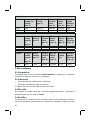
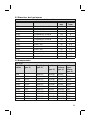
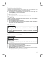
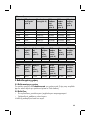
(siehe Abb.2)
Kenn
zeichen
Ober
schen
kel
schiene
(Pos.1)
Gelenk
(Pos.2)
Gelenk
schrau
be
(Pos.3)
Siche
rungs
schrau
be
(Pos.4)
Kugella
ger
(Pos.5)
Unter
schen
kel
schiene
(Pos.6)
7U10 7A9* 7Y12 501A24* 501S10 509K11* 7A8*
4

(siehe Abb.2)
Kenn
zeichen
Ober
schen
kel
schiene
(Pos.1)
Gelenk
(Pos.2)
Gelenk
schrau
be
(Pos.3)
Siche
rungs
schrau
be
(Pos.4)
Buchse
(ohne
Abb.)
Unter
schen
kel
schiene
(Pos.6)
7U27 7A10* 7Y13 501A32 501S22* 7Y14** 7B10*
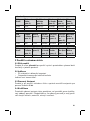
3 Bestimmungsgemäße Verwendung
3.1 Verwendungszweck
Das Produkt ist ausschließlich paarweise zur prothetischen Versorgung
der unteren Extremität bei einem Patienten einzusetzen.
3.2 Indikationen
• Bei unilateraler oder bilateraler Amputation
• Orthopädische Erkrankungen der unteren Extremität
Die Indikation wird vom Arzt gestellt.
3.3 Lebensdauer
Das Produkt ist bei bestimmungsgemäßer Verwendung und fachgerechter
Montage für eine Lebensdauer von 3Jahren ausgelegt.
3.4 Qualifikation
Die Versorgung eines Patienten mit dem Produkt darf nur von ausgebilde
tem Fachpersonal vorgenommen werden. Es wird vorausgesetzt, dass das
Fachpersonal im Umgang mit den unterschiedlichen Techniken, Materialien,
Werkzeugen und Maschinen vertraut ist.
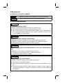
4 Sicherheit
4.1 Bedeutung der Warnsymbolik
VORSICHT Warnung vor möglichen Unfall- und Verletzungsgefahren.
HINWEIS Warnung vor möglichen technischen Schäden.
4.2 Sicherheitshinweise
VORSICHT
Überbeanspruchung tragender Bauteile
Verletzungen durch Funktionsveränderung oder –verlust
►Verwenden Sie das Produkt nur für den definierten Einsatzbereich.
5

►Falls das Produkt extremen Belastungen ausgesetzt wurde (z.B. durch
Sturz), sorgen Sie für geeignete Maßnahmen (z.B. Reparatur, Aus
tausch, Kontrolle durch den Kundenservice des Herstellers, etc.).
VORSICHT
Fehlerhafter Aufbau, Montage oder Einstellung
Verletzungsgefahr durch Funktionsveränderung oder -verlust
►Montage-, Einstell-, und Wartungsarbeiten dürfen nur von Fachperso
nal durchgeführt werden.
►Beachten Sie die Aufbau-, Montage- und Einstellhinweise.
VORSICHT
Überbeanspruchung durch Gebrauch an mehr als einem Patienten
Verletzungsgefahr und Funktionsverlust sowie Beschädigungen am Pro
dukt
►Verwenden Sie das Produkt nur an einem Patienten.
►Beachten Sie die Wartungsempfehlung.
VORSICHT
Mechanische Beschädigung des Produkts
Verletzungen durch Funktionsveränderung oder –verlust
►Arbeiten Sie sorgfältig mit dem Produkt.
►Prüfen Sie das Produkt auf Funktion und Gebrauchsfähigkeit.
►Verwenden Sie das Produkt bei Funktionsveränderungen oder -verlust
nicht weiter und lassen Sie es durch autorisiertes Fachpersonal kon
trollieren.
HINWEIS
Produkt wird falschen Umgebungsbedingungen ausgesetzt
Beschädigungen, Versprödung oder Zerstörung durch unsachgemäße
Handhabung
►Vermeiden Sie die Lagerung bei kondensierender Umgebungsfeuch
tigkeit.
►Vermeiden Sie den Kontakt mit abrasiven Medien (z.B. Sand, Staub).
►Setzen Sie das Produkt keinen Temperaturen unter -10°C und über
+60°C aus (z.B. Sauna, übermäßiger Sonneneinstrahlung, Trocknen
auf der Heizung).
6

5 Gebrauchsfähigkeit herstellen
VORSICHT
Wiederholtes Schränken an der gleichen Stelle
Verletzungsgefahr durch Bruch der Schiene, Funktionsveränderung oder
–verlust
►Vermeiden Sie wiederholtes Schränken an der gleichen Stelle.
HINWEIS
Fehlende parallele Ausrichtung der Gelenke
Mechanischer Verschleiß
►Das Parallelrichtgerät 743R3 oder 743R5 verwenden.
INFORMATION
Korrosionsschutz der Schienen
Die Schienen bestehen aus rost- und säurebeständigem Stahl. Feinschlei
fen und Polieren erhöhen den Korrosionsschutz der Schienen.
Ottobock empfiehlt zur Beschichtung das 618T40 Sinterpulver.
Schienen anrichten
>Benötigte Werkzeuge: Parallelrichtgerät 743R3 oder 743R5, Schränk
eisen 711S5.
1) Die Ausrichtung der Schienen am Modell prüfen.
2) Das Gelenk demontieren.
3) Die Schienen mit Schränkeisen anpassen.
HINWEIS: Beschädigen Sie nicht die oberflächengehärteten Zahn
segmente der 7U10* und 7U27* Gelenke.
4) Die Anpassung am Modell überprüfen.
5) Die Arbeitsschritte wiederholen bis das gewünschte Ergebnis erzielt ist.
6) Die Riefen und Grate durch Schleifen entfernen.
Schienenoberflächen 7U46 bearbeiten
> Die 7U46 Beinschienen können in einer wasserfesten Gehhilfe verwen
det werden.
►Die Schienenoberflächen allseitig polieren.
7

Korrosionsschutz verbessern
Zur Verbesserung des Korrosionsschutzes das Produkt polieren oder sin
tern. Für die Oberflächenbeschichtung empfiehlt Ottobock das Sinterpulver
618T40*.
►Zum Oberflächebeschichten das Material nicht länger als 5 Minuten
und bei maximal 150°C erwärmen.
Schutzvorrichtung verwenden
►Verwenden Sie Gelenkschützer, um das Produkt vor Schmutz zu schüt
zen.
6 Reinigung
Das Produkt nach dem Kontakt mit salz-, chlor- oder seifenhaltigen Wasser
oder bei Verschmutzungen umgehend reinigen.
1) Das Produkt mit reinem Süßwasser abspülen.
2) Das Produkt mit einem Tuch abtrocknen oder an der Luft trocknen las
sen. Direkte Hitzeeinwirkung vermeiden (z.B. Ofen- oder Heizkörperhit
ze).
7 Wartung
INFORMATION
Möglicherweise ist das Produkt patientenspezifisch einer erhöhten
Belastung ausgesetzt.
►Verkürzen Sie die Wartungsintervalle gemäß den zu erwartenden Be
lastungen.
Der Hersteller schreibt für das Produkt mindestens eine halbjährliche Funkti
ons- und Verschleißkontrolle vor.
Nur Spezialschmiermittel 633F7 verwenden.
Kugellager auswechseln
HINWEIS
Verkanten des Kugellagers
Mechanische Beschädigung
►Das Kugellager beim Einsetzen in das Orthesengelenk nicht verkanten
oder beschädigen.
1) Die Schrauben lösen und das Orthesengelenk demontieren.
2) Das Kugellager aus dem Orthesengelenk entfernen und durch ein neues
ersetzen.
3) Das Orthesengelenk montieren und die Schrauben anziehen.
8

4) Sicherungschraube: Die Gewinde der Schraubverbindungen mit einem
entfettenden Reiniger reinigen und mit Loctite 241 sichern.
8 Entsorgung
Das Produkt gemäß den geltenden nationalen Vorschriften entsorgen.
9 Rechtliche Hinweise
Alle rechtlichen Bedingungen unterliegen dem jeweiligen Landesrecht des
Verwenderlandes und können dementsprechend variieren.
9.1 Haftung
Der Hersteller haftet, wenn das Produkt gemäß den Beschreibungen und
Anweisungen in diesem Dokument verwendet wird. Für Schäden, die durch
Nichtbeachtung dieses Dokuments, insbesondere durch unsachgemäße
Verwendung oder unerlaubte Veränderung des Produkts verursacht werden,
haftet der Hersteller nicht.
9.2 CE-Konformität
Das Produkt erfüllt die Anforderungen der Verordnung (EU) 2017/745 über
Medizinprodukte. Die CE-Konformitätserklärung kann auf der Website des
Herstellers heruntergeladen werden.
1 Foreword English
INFORMATION
Date of last update: 2021-09-23
►Please read this document carefully before using the product and
observe the safety notices.
►Instruct the user in the safe use of the product.
►Please contact the manufacturer if you have questions about the
product or in case of problems.
►Report each serious incident related to the product to the manufacturer
and to the relevant authority in your country. This is particularly import
ant when there is a decline in the health state.
►Please keep this document for your records.
These instructions for use provide you with important information on the pro
cessing of the 7G3, 7U2*, 7U10, 7U15*, 7U25, 7U26, 7U27, 7U30*, 7U32*,
7U33, 7U42, 7U43 and 7U46 lower leg joint bars.
9

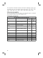
2 Product description
The lower leg knee joint bars are suitable for the fabrication of a transtibial
prosthesis with a thigh sleeve.
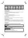
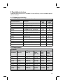
2.1 Available sizes
Lower leg joint bars
Reference number Material Width in
mm
Thick
ness in
mm
7G3 Orthopaedic steel, nickel-
plated
23 5
7U2* Orthopaedic steel 24 3
7U10 Orthopaedic steel 24 3
7U15* Orthopaedic steel, nickel-
plated
24 3
7U25 Orthopaedic steel, nickel-
plated
24 3
7U26 Orthopaedic steel, nickel-
plated
22 2.5
7U27 Stainless steel 20 3
7U30* Stainless steel 20 2.3
7U32* Stainless steel 20 2.3
7U33 Stainless steel 20 2.3
7U42 Stainless steel 20 2.3
7U43 Orthopaedic steel 22 2.5
7U46 Stainless steel 20 1.75
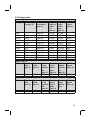
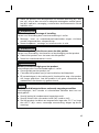
2.2 Components
(see fig.1)
Refer
ence
number
Upper joint
bar section
(item1)
Ball bearing
(item2)
Joint
screw
(item3)
Lock
screw
(item4)
Lower
joint bar
section
(item5)
7G3 509K11* 501A22 501S6*
7U2* 7A1* 509K11* 501A25 501S22* 7B3*
7U15* 7A11* 509K11* 501A22 501S6* 7B13*
7U25 7A11* 509K11* 501A22 501S6* 7B13*
10

(see fig.1)
Refer
ence
number
Upper joint
bar section
(item1)
Ball bearing
(item2)
Joint
screw
(item3)
Lock
screw
(item4)
Lower
joint bar
section
(item5)
7U26 7A12* 509K11* 501A22 501S6* 7B12*
7U30* 7A5* 509K11* 501A6 501S22* 7B5*
7U32* 7A6* 509K11* 501A6 501S22* 7B5*
7U33 7A5* 509K11* 501A6 501S22* 7B5*
7U42 7A6* 509K11* 501A6 501S22* 7B5*
7U43 7A3* 509K11* 501A25 501S22* 7B4*
7U46 7A14* 509K15 501A12 501S22* 7B7*
(see fig.2)
Refer
ence
number
Upper
joint bar
section
(item1)
Joint
(item2)
Joint
screw
(item3)
Lock
screw
(item4)
Ball
bearing
(item5)
Lower
joint bar
section
(item6)
7U10 7A9* 7Y12 501A24* 501S10 509K11* 7A8*
(see fig.2)
Refer
ence
number
Upper
joint bar
section
(item1)
Joint
(item2)
Joint
screw
(item3)
Lock
screw
(item4)
Bushing
(not
illus
trated)
Lower
joint bar
section
(item6)
7U27 7A10* 7Y13 501A32 501S22* 7Y14** 7B10*
3 Intended use
3.1 Indications for use
The product is intended exclusively for use in pairs for prosthetic fittings of
the lower limbs on one patient.
3.2 Indications
• For unilateral or bilateral amputation
• Orthopaedic diseases of the lower limbs
Indications must be determined by the physician.
3.3 Lifetime
The product is designed for a lifetime of 3years when used as intended and
assembled professionally.
11

3.4 Qualification
Patients may be fitted with the product only by trained qualified personnel.
The qualified personnel must be familiar with the handling of the various
techniques, materials, machines and tools.
4 Safety
4.1 Explanation of warning symbols
CAUTION Warning regarding possible risks of accident or injury.
NOTICE Warning regarding possible technical damage.
4.2 Safety instructions
CAUTION
Excessive strain on load-bearing components
Injuries due to changes in or loss of functionality
►Only use the product for the defined area of application.
►If the product has been exposed to extreme strain (e.g.due to falling),
take any necessary measures (e.g.repair, replacement, inspection by
the manufacturer's customer service, etc.).
CAUTION
Incorrect alignment, assembly or adjustment
Risk of injury due to change in or loss of functionality
►Assembly, adjustment and maintenance operations may only be com
pleted by qualified personnel.
►Observe the alignment, assembly and adjustment instructions.
CAUTION
Excessive strain due to use on more than one patient
Risk of injury and loss of functionality as well as damage to the product
►Use the product on only one patient.
►Observe the maintenance recommendations.
CAUTION
Mechanical damage to the product
Injuries due to changes in or loss of functionality
►Use caution when working with the product.
12

►Check the product for proper function and readiness for use.
►In case of changes in or loss of functionality, discontinue use of the
product and have it checked by authorised, qualified personnel.
NOTICE
Exposure of the product to unsuitable environmental conditions
Damage, brittleness or destruction due to improper handling
►Avoid storage in condensing ambient humidity.
►Avoid contact with abrasive substances (e.g.sand, dust).
►Do not expose the product to temperatures below -10°C (14°F) or
above +60°C (140°F) (e.g.sauna, excessive sunlight, drying on a
radiator).
5 Preparing the product for use
CAUTION
Repeated bending at the same position
Risk of injury due to breakage of the bar, change in or loss of functionality
►Avoid repeated bending at the same position.
NOTICE
Lack of parallel alignment of the joints
Mechanical wear and tear
►Use the 743R3 or 743R5 parallel alignment tool.
INFORMATION
Corrosion protection of the bars
The bars are made of corrosion and acid-resistant steel. Fine grinding and
polishing improve corrosion protection of the bars.
Ottobock recommends the 618T40 sintering powder for coating.
Shaping the bars
>Required tools: 743R3 or 743R5 parallel alignment tool, 711S5 bend
ing irons.
1) Check the alignment of the bars on the model.
2) Disassemble the joint.
3) Adapt the bars with the bending irons.
NOTICE: Do not damage the surface hardened toothed segments
of the 7U10* and 7U27* joints.
13

4) Check the adaptation on the model.
5) Repeat the steps until the desired result is obtained.
6) Remove grooves and burrs by grinding.
Finishing the surfaces of the 7U46 bars
> The 7U46 knee joint bars can be used in a waterproof walking aid.
►Polish the surfaces of the bars on all sides.
Improving corrosion protection
Polish or sinter the product for improved corrosion protection. Ottobock
recommends the 618T40* sintering powder for surface coating.
►Do not heat the material longer than 5minutes at max. 150°C for sur
face coating.
Using protective devices
►Use joint protectors to protect the product against soiling.
6 Cleaning
Promptly clean the product after contact with water containing salt, chlorine
or soap, or if it gets dirty.
1) Rinse the product with clear fresh water.
2) Dry the product with a cloth or allow it to air dry. Avoid exposure to direct
heat (e.g. from an oven or radiator).
7 Maintenance
INFORMATION
The product may be exposed to increased loads by the patient.
►Shorten the maintenance intervals according to the expected loads.
The manufacturer requires at least a semi-annual inspection of the product
to verify functionality and check for wear.
Only use 633F7 special lubricant.
Replacing the ball bearing
NOTICE
Canting the ball bearing
Mechanical damage
►Do not cant or damage the ball bearing while inserting it into the orthot
ic joint.
1) Loosen the screws and disassemble the orthotic joint.
14

2) Remove the ball bearing from the orthotic joint and replace it with a new
one.
3) Assemble the orthotic joint and tighten the screws.
4) Lock screw: Clean the threads of the screw connections using a
degreasing cleaner and secure them with Loctite241.
8 Disposal
Dispose of the product in accordance with national regulations.
9 Legal information
All legal conditions are subject to the respective national laws of the country
of use and may vary accordingly.
9.1 Liability
The manufacturer will only assume liability if the product is used in accord
ance with the descriptions and instructions provided in this document. The
manufacturer will not assume liability for damage caused by disregarding the
information in this document, particularly due to improper use or unauthor
ised modification of the product.
9.2 CE conformity
The product meets the requirements of Regulation (EU) 2017/745 on medic
al devices. The CE declaration of conformity can be downloaded from the
manufacturer's website.
1 Avant-propos Français
INFORMATION
Date de la dernière mise à jour: 2021-09-23
►Veuillez lire attentivement l’intégralité de ce document avant d’utiliser le
produit ainsi que respecter les consignes de sécurité.
►Apprenez à l’utilisateur comment utiliser son produit en toute sécurité.
►Adressez-vous au fabricant si vous avez des questions concernant le
produit ou en cas de problèmes.
►Signalez tout incident grave survenu en rapport avec le produit, notam
ment une aggravation de l’état de santé, au fabricant et à l’autorité
compétente de votre pays.
►Conservez ce document.
15

La notice d’utilisation fournit d’importantes informations sur le traitement des
ferrures de jambe 7G3, 7U2*, 7U10, 7U15*, 7U25, 7U26, 7U27, 7U30*,
7U32*, 7U33, 7U42, 7U43 et 7U46.
2 Description du produit
Les ferrures de jambe sont destinées à la confection d’une prothèse tibiale à
l’aide d’un manchon fémoral.
2.1 Tailles disponibles
Ferrures de jambe
Référence Matériau Largeur
en mm
Épais
seur en
mm
7G3 Acier orthopédique, nickelé 23 5
7U2* Acier orthopédique 24 3
7U10 Acier orthopédique 24 3
7U15* Acier orthopédique, nickelé 24 3
7U25 Acier orthopédique, nickelé 24 3
7U26 Acier orthopédique, nickelé 22 2.5
7U27 Acier inoxydable 20 3
7U30* Acier inoxydable 20 2.3
7U32* Acier inoxydable 20 2.3
7U33 Acier inoxydable 20 2.3
7U42 Acier inoxydable 20 2.3
7U43 Acier orthopédique 22 2.5
7U46 Acier inoxydable 20 1.75
2.2 Composants
(voir ill.1)
Réfé
rence
Ferrure fé
morale
(pos.1)
Roulement
à billes
(pos.2)
Vis
d’articul
ation
(pos.3)
Vis de
blocage
(pos.4)
Ferrure
tibiale
(pos.5)
7G3 509K11* 501A22 501S6*
7U2* 7A1* 509K11* 501A25 501S22* 7B3*
7U15* 7A11* 509K11* 501A22 501S6* 7B13*
7U25 7A11* 509K11* 501A22 501S6* 7B13*
16

(voir ill.1)
Réfé
rence
Ferrure fé
morale
(pos.1)
Roulement
à billes
(pos.2)
Vis
d’articul
ation
(pos.3)
Vis de
blocage
(pos.4)
Ferrure
tibiale
(pos.5)
7U26 7A12* 509K11* 501A22 501S6* 7B12*
7U30* 7A5* 509K11* 501A6 501S22* 7B5*
7U32* 7A6* 509K11* 501A6 501S22* 7B5*
7U33 7A5* 509K11* 501A6 501S22* 7B5*
7U42 7A6* 509K11* 501A6 501S22* 7B5*
7U43 7A3* 509K11* 501A25 501S22* 7B4*
7U46 7A14* 509K15 501A12 501S22* 7B7*
(voir ill.2)
Réfé
rence
Ferrure
fémo
rale
(pos.1)
Articu
lation
(pos. 2)
Vis
d’articu
lation
(pos.3)
Vis de
blocage
(pos.4)
Roule
ment à
billes
(pos.5)
Ferrure
tibiale
(pos.6)
7U10 7A9* 7Y12 501A24* 501S10 509K11* 7A8*
(voir ill.2)
Réfé
rence
Ferrure
fémo
rale
(pos.1)
Articu
lation
(pos. 2)
Vis
d’articu
lation
(pos.3)
Vis de
blocage
(pos.4)
Douille
(sans
ill.)
Ferrure
tibiale
(pos.6)
7U27 7A10* 7Y13 501A32 501S22* 7Y14** 7B10*
3 Utilisation conforme
3.1 Usage prévu
Le produit doit être utilisé exclusivement par paire pour l’appareillage pro
thétique du membre inférieur d’un patient.
3.2 Indications
• En cas d’amputation unilatérale ou bilatérale
• Maladies orthopédiques du membre inférieur
L’indication est déterminée par le médecin.
3.3 Durée de vie
Le produit est conçu pour une durée de vie de 3ans si son utilisation est
conforme et le montage correct.
17

3.4 Qualification
Seul un personnel spécialisé dûment formé est autorisé à appareiller un pa
tient avec le produit. Il est entendu que ces professionnels sont familiarisés
à l’utilisation des diverses méthodes et différents matériaux, outils et ma
chines requis.
4 Sécurité
4.1 Signification des symboles de mise en garde
PRUDENCE Mise en garde contre les éventuels risques d’accidents
et de blessures.
AVIS Mise en garde contre les éventuels dommages tech
niques.
4.2 Consignes de sécurité
PRUDENCE
Sollicitation excessive des éléments porteurs
Blessures dues à une modification ou une perte de fonctionnalité
►Veuillez utiliser le produit uniquement dans le champ d’application défi
ni.
►Si le produit a été soumis à des sollicitations extrêmes (parex. en cas
de chute), prenez les mesures nécessaires (parex. réparation, rempla
cement, contrôle par le service après-vente du fabricant, etc.).
PRUDENCE
Alignement, montage ou réglage incorrects
Risque de blessure occasionnée par une modification ou une perte de
fonctionnalité
►Seul le personnel spécialisé est autorisé à effectuer les opérations de
montage, de réglage et de maintenance.
►Respectez les consignes relatives à l’alignement, au montage et au ré
glage.
PRUDENCE
Sollicitation excessive due à un usage par plusieurs patients
Risque de blessure et perte de fonctionnalité ainsi que dégradations du
produit
►N’utilisez le produit que sur un seul patient.
18

►Respectez les recommandations en matière de maintenance.
PRUDENCE
Dégradation mécanique du produit
Blessures dues à une modification ou une perte de fonctionnalité
►Manipulez le produit avec précaution.
►Vérifiez le produit afin de juger s’il est encore fonctionnel.
►Cessez d’utiliser le produit en cas de modifications ou de pertes fonc
tionnelles et faites-le contrôler par un personnel spécialisé agréé.
AVIS
Produit exposé à des conditions d’environnement inappropriées
Détériorations, fragilisation ou destruction dues à une manipulation incor
recte
►Évitez de stocker le produit dans un environnement humide avec de la
condensation.
►Évitez tout contact avec des éléments abrasifs (p.ex. le sable et la
poussière).
►N’exposez pas le produit à des températures inférieures à -10°C ou à
des températures supérieures à +60°C (p.ex. sauna, fort rayonnement
solaire, séchage sur un radiateur).
5 Mise en service du produit
PRUDENCE
Pliage répété au même endroit
Risque de blessure occasionnée par une rupture de la ferrure, une modifi
cation de fonctionnalité voire une perte de fonctionnalité
►Éviter un pliage répété au même endroit.
AVIS
Absence de parallélisme des articulations
Usure mécanique
►Utiliser l’appareil de parallélisme 743R3 ou 743R5.
INFORMATION
Protection anti-corrosion des ferrures
19

Les ferrures se composent d’acier résistant à la corrosion et aux acides.
Un ponçage de précision et un polissage favorisent la protection contre la
corrosion des ferrures.
Ottobock recommande d’utiliser la poudre frittée 618T40 pour le revête
ment.
Orientation des ferrures
>Outils requis: appareil de parallélisme 743R3 ou 743R5, cintreuse
711S5.
1) Vérifier le sens des ferrures sur le modèle.
2) Démonter l’articulation.
3) Ajuster les ferrures à l’aide d’une cintreuse.
AVIS: ne pas endommager les segments dentés trempés des arti
culations 7U10* et 7U27*.
4) Vérifier l’ajustement sur le modèle.
5) Répéter les étapes de travail jusqu’à obtenir le résultat souhaité.
6) Poncer pour supprimer les stries et ébarbures.
Traitement des surfaces de ferrure 7U46
> Les ferrures de jambe 7U46 peuvent être utilisées dans une aide à la
marche résistante à l’eau.
►Polir les surfaces de ferrure de tout côté.
Amélioration de la protection anti-corrosion
Polir ou fritter le produit pour en améliorer la protection anti-corrosion.
Ottobock recommande la poudre frittée 618T40* pour le revêtement de sur
face.
►Pour le revêtement de surface, ne pas chauffer le matériau plus de 5mi
nutes et à max. 150°C.
Utilisation d’un dispositif de protection
►Utiliser des protège-articulations pour protéger le produit contre les sa
lissures.
6 Nettoyage
Après tout contact avec de l’eau salée, chlorée ou savonneuse ou en cas de
salissures, nettoyez immédiatement le produit.
1) Rincez le produit à l’eau douce et claire.
2) Essuyez le produit avec un chiffon ou laissez-le sécher à l’air libre. Évitez
toute exposition directe à la chaleur (p.ex. la chaleur des poêles ou des
radiateurs).
20
Sayfa yükleniyor...
Sayfa yükleniyor...
Sayfa yükleniyor...
Sayfa yükleniyor...
Sayfa yükleniyor...
Sayfa yükleniyor...
Sayfa yükleniyor...
Sayfa yükleniyor...
Sayfa yükleniyor...
Sayfa yükleniyor...
Sayfa yükleniyor...
Sayfa yükleniyor...
Sayfa yükleniyor...
Sayfa yükleniyor...
Sayfa yükleniyor...
Sayfa yükleniyor...
Sayfa yükleniyor...
Sayfa yükleniyor...
Sayfa yükleniyor...
Sayfa yükleniyor...
Sayfa yükleniyor...
Sayfa yükleniyor...
Sayfa yükleniyor...
Sayfa yükleniyor...
Sayfa yükleniyor...
Sayfa yükleniyor...
Sayfa yükleniyor...
Sayfa yükleniyor...
Sayfa yükleniyor...
Sayfa yükleniyor...
Sayfa yükleniyor...
Sayfa yükleniyor...
Sayfa yükleniyor...
Sayfa yükleniyor...
Sayfa yükleniyor...
Sayfa yükleniyor...
Sayfa yükleniyor...
Sayfa yükleniyor...
Sayfa yükleniyor...
Sayfa yükleniyor...
Sayfa yükleniyor...
Sayfa yükleniyor...
Sayfa yükleniyor...
Sayfa yükleniyor...
Sayfa yükleniyor...
Sayfa yükleniyor...
Sayfa yükleniyor...
Sayfa yükleniyor...
Sayfa yükleniyor...
Sayfa yükleniyor...
Sayfa yükleniyor...
Sayfa yükleniyor...
Sayfa yükleniyor...
Sayfa yükleniyor...
Sayfa yükleniyor...
Sayfa yükleniyor...
Sayfa yükleniyor...
Sayfa yükleniyor...
Sayfa yükleniyor...
Sayfa yükleniyor...
Sayfa yükleniyor...
Sayfa yükleniyor...
Sayfa yükleniyor...
Sayfa yükleniyor...
Sayfa yükleniyor...
Sayfa yükleniyor...
Sayfa yükleniyor...
Sayfa yükleniyor...
Sayfa yükleniyor...
Sayfa yükleniyor...
Sayfa yükleniyor...
Sayfa yükleniyor...
Sayfa yükleniyor...
Sayfa yükleniyor...
Sayfa yükleniyor...
Sayfa yükleniyor...
Sayfa yükleniyor...
Sayfa yükleniyor...
Sayfa yükleniyor...
Sayfa yükleniyor...
Sayfa yükleniyor...
Sayfa yükleniyor...
Sayfa yükleniyor...
Sayfa yükleniyor...
Sayfa yükleniyor...
Sayfa yükleniyor...
Sayfa yükleniyor...
Sayfa yükleniyor...
-
 1
1
-
 2
2
-
 3
3
-
 4
4
-
 5
5
-
 6
6
-
 7
7
-
 8
8
-
 9
9
-
 10
10
-
 11
11
-
 12
12
-
 13
13
-
 14
14
-
 15
15
-
 16
16
-
 17
17
-
 18
18
-
 19
19
-
 20
20
-
 21
21
-
 22
22
-
 23
23
-
 24
24
-
 25
25
-
 26
26
-
 27
27
-
 28
28
-
 29
29
-
 30
30
-
 31
31
-
 32
32
-
 33
33
-
 34
34
-
 35
35
-
 36
36
-
 37
37
-
 38
38
-
 39
39
-
 40
40
-
 41
41
-
 42
42
-
 43
43
-
 44
44
-
 45
45
-
 46
46
-
 47
47
-
 48
48
-
 49
49
-
 50
50
-
 51
51
-
 52
52
-
 53
53
-
 54
54
-
 55
55
-
 56
56
-
 57
57
-
 58
58
-
 59
59
-
 60
60
-
 61
61
-
 62
62
-
 63
63
-
 64
64
-
 65
65
-
 66
66
-
 67
67
-
 68
68
-
 69
69
-
 70
70
-
 71
71
-
 72
72
-
 73
73
-
 74
74
-
 75
75
-
 76
76
-
 77
77
-
 78
78
-
 79
79
-
 80
80
-
 81
81
-
 82
82
-
 83
83
-
 84
84
-
 85
85
-
 86
86
-
 87
87
-
 88
88
-
 89
89
-
 90
90
-
 91
91
-
 92
92
-
 93
93
-
 94
94
-
 95
95
-
 96
96
-
 97
97
-
 98
98
-
 99
99
-
 100
100
-
 101
101
-
 102
102
-
 103
103
-
 104
104
-
 105
105
-
 106
106
-
 107
107
-
 108
108


diğer dillerde
- slovenčina: Ottobock 7G3 Používateľská príručka
- français: Ottobock 7G3 Manuel utilisateur
- dansk: Ottobock 7G3 Brugermanual
İlgili makaleler
-
Ottobock 17B82 Kullanma talimatları
-
-
-
-
-
Ottobock 17B95 Kullanım kılavuzu
-
-
-
-
Ottobock 3R93 Kullanım kılavuzu
Diğer belgeler
-
Otto Bock Genu Direxa wraparound 8353 Instructions For Use Manual
-
Yamaha CLP-560 El kitabı
-
-
Stiga SWP 577 Kullanma talimatları
-
Grundfos E Series Installation And Operating Instructions Manual
-
Castorama Porte d'entrée acier Hublots inserts gris anthracite 90 x h.h.215 cm poussant gauche El kitabı