Yamaha NS-SWP600 Kullanım kılavuzu
- Kategori
- Alıcı
- Tip
- Kullanım kılavuzu

(YSP-CU2200 + NS-SWP600)
(YSP-CU2200 + NS-SWP600)
Digital Sound Projector™
OWNER’S MANUAL
English

i En
CAUTION: READ THIS BEFORE OPERATING YOUR UNIT.
1 To assure the finest performance, please read this manual
carefully. Keep it in a safe place for future reference.
2 Install this unit in a well ventilated, cool, dry, clean place –
away from direct sunlight, heat sources, vibration, dust,
moisture, and/or cold. For proper ventilation, allow the
following minimum clearances.
Top : 5 cm (2 in)
Rear: 5 cm (2 in)
Sides: 1 cm (13/32 in)
3 Locate this unit away from other electrical appliances,
motors, or transformers to avoid humming sounds.
4 Do not expose this unit to sudden temperature changes from
cold to hot, and do not locate this unit in an environment with
high humidity (i.e. a room with a humidifier) to prevent
condensation inside this unit, which may cause an electrical
shock, fire, damage to this unit, and/or personal injury.
5 Avoid installing this unit where foreign object may fall onto
this unit and/or this unit may be exposed to liquid dripping or
splashing. On the top of this unit, do not place:
– Other components, as they may cause damage and/or
discoloration on the surface of this unit.
– Burning objects (i.e. candles), as they may cause fire,
damage to this unit, and/or personal injury.
– Containers with liquid in them, as they may fall and
liquid may cause electrical shock to the user and/or
damage to this unit.
6 Do not cover this unit with a newspaper, tablecloth, curtain,
etc. in order not to obstruct heat radiation. If the temperature
inside this unit rises, it may cause fire, damage to this unit,
and/or personal injury.
7 Do not plug in this unit to a wall outlet until all connections
are complete.
8 Do not operate this unit upside-down. It may overheat,
possibly causing damage.
9 Do not use force on switches, knobs and/or cords.
10 When disconnecting the power cable from the wall outlet,
grasp the plug; do not pull the cable.
11 Do not clean this unit with chemical solvents; this might
damage the finish. Use a clean, dry cloth.
12 Only voltage specified on this unit must be used. Using this
unit with a higher voltage than specified is dangerous and
may cause fire, damage to this unit, and/or personal injury.
Yamaha will not be held responsible for any damage resulting
from use of this unit with a voltage other than specified.
13 To prevent damage by lightning, keep the power cable
disconnected from a wall outlet or this unit during a lightning
storm.
14 Do not attempt to modify or fix this unit. Contact qualified
Yamaha service personnel when any service is needed. The
cabinet should never be opened for any reasons.
15 When not planning to use this unit for long periods of time
(i.e. vacation), disconnect the AC power plug from the wall
outlet.
16 Be sure to read the “TROUBLESHOOTING” section on
common operating errors before concluding that this unit is
faulty.
17 Before moving this unit, press p to set this unit to the
standby mode, and disconnect the AC power plug from the
wall outlet.
18 Condensation will form when the surrounding temperature
changes suddenly. Disconnect the power cable from the
outlet, then leave this unit alone.
19 When using this unit for a long time, this unit may become
warm. Turn the power off, then leave this unit alone for
cooling.
20 Install this unit near the AC outlet and where the AC power
plug can be reached easily.
21 The batteries shall not be exposed to excessive heat such as
sunshine, fire or the like. When you dispose of batteries,
follow your regional regulations.
WARNING
TO REDUCE THE RISK OF FIRE OR ELECTRIC SHOCK, DO
NOT EXPOSE THIS UNIT TO RAIN OR MOISTURE.
WARNING
THE POWER SUPPLY CABLE OF THIS UNIT MUST BE
CONNECTED TO THE MAIN SOCKET OUTLET VIA A
PROTECTIVE EARTHING CONNECTION.
This unit is not disconnected from the AC power source as long as
it is connected to the wall outlet, even if this unit itself is turned off
by p. This state is called the standby mode. In this state, this unit
is designed to consume a very small quantity of power.

ii En
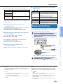
■ For U.K. customers
If the socket outlets in the home are not suitable for the plug supplied
with this appliance, it should be cut off and an appropriate 3 pin plug
fitted. For details, refer to the instructions described below.
The plug severed from the mains lead must be destroyed, as a plug
with bared flexible cord is hazardous if engaged in a live socket outlet.
■ Special Instructions for U.K. Model
■ Notes on remote controls and batteries
• Do not spill water or other liquids on the remote control.
• Do not drop the remote control.
• Do not leave or store the remote control in the following conditions:
– places of high humidity, such as near a bath
– places of high temperatures, such as near a heater or stove
– places of extremely low temperatures
– dusty places
• Insert the battery according to the polarity markings (+ and -).
• Change all batteries if you notice the following conditions: the
operation range of the remote control narrows or the transmit
indicator does not flash or is dim.
• If the batteries run out, immediately remove them from the remote
control to prevent an explosion or acid leak.
• If you find leaking batteries, discard the batteries immediately,
taking care not to touch the leaked material. If the leaked material
comes into contact with your skin or gets into your eyes or mouth,
rinse it away immediately and consult a doctor. Clean the battery
compartment thoroughly before installing new batteries.
• Do not use old batteries together with new ones. This may shorten
the life of the new batteries or cause old batteries to leak.
• Do not use different types of batteries (such as alkaline and
manganese batteries) together. Specification of batteries may be
different even though they look the same.
• Before inserting new batteries, wipe the compartment clean.
• Dispose of batteries according to your regional regulations.
Note
IMPORTANT
THE WIRES IN MAINS LEAD ARE COLOURED IN
ACCORDANCE WITH THE FOLLOWING CODE:
Blue: NEUTRAL
Brown: LIVE
As the colours of the wires in the mains lead of this apparatus may
not correspond with the coloured markings identifying the
terminals in your plug, proceed as follows:
The wire which is coloured BLUE must be connected to the
terminal which is marked with the letter N or coloured BLACK.
The wire which is coloured BROWN must be connected to the
terminal which is marked with the letter L or coloured RED.
Making sure that neither core is connected to the earth terminal of
the three pin plug.
1 En

2 En
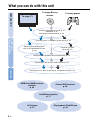
What you can do with this unit
To enjoy TV
To enjoy Blu-ray
movies
To enjoy games
Checking supplied accessories (p. 4)
Installation (p. 9)
Preparing the remote control (p. 13)
Connecting your TV and Blu-ray disc player (p. 14)
Operating the unit by TV’s remote control (p. 24)
When enjoying STB program
such as on satellite/CATV tuner
(p. 15)
Connecting a game
console (p. 15)
Playing back a TV, Blu-ray disc player, and game console (p. 26)
PREPARATION
CONNECTION/
INITIAL SETTINGS
PLAYBACK
Setting the best possible sound automatically (p. 17)
HDMI link (HDMI control)
function
p. 24
Cinema DSP function
p. 28
IntelliBeam function
p. 17
UniVolume
p. 27
Playing back iPod/iPhone
p. 33

3 En
PREPARATION
CONNECTION/
INITIAL SETTINGS PLAYBACK SETTINGS
TROUBLESHOOTING
APPENDIX
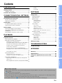
Contents
PREPARATION
Getting started ....................................................... 4
Supplied accessories .................................................... 4
Controls and functions.......................................... 5
CONNECTION/INITIAL SETTINGS
Installation and Connection.................................. 9
Remote control preparation......................................... 13
Subwoofer connection................................................. 13
Connections ......................................................... 14
TV and Blu-ray disc player connection........................ 14
Game console or tuner connection ............................. 15
Initial settings....................................................... 16
Selecting language for menu display .......................... 16
Auto setup for appropriate surround effects
(IntelliBeam)................................................................ 17
Operating the unit by TV’s remote control................... 24
PLAYBACK
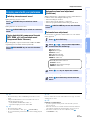
Playback features ................................................ 26
Basic operation for playback ....................................... 26
Enjoying sound with your preference.......................... 27
Switching stereo/surround sound.......................................27
Playing back digitally compressed formats (MP3, WMA, etc.)
with enriched sound (Compressed Music Enhancer).........27
Automatic volume level adjustment (UniVolume)...............27
Volume balance adjustment............................................... 27
Enjoying realistic surround sound (CINEMA DSP).............28
Changing the audio output method for surround playback
...........................................................................................29
Surround decoder setting...................................................31
Using useful features .................................................. 32
Sleep timer/auto power down function ............................... 32
Settings for each input source (Option menu).................... 32
Playing back iPod/iPhone ........................................... 33
When using Yamaha Universal Dock for iPod (optional
YDS-12, etc.)...................................................................... 34
When using Wireless System for iPod (optional YID-W10)
...........................................................................................34
Playing back Bluetooth components ...........................35
Pairing................................................................................ 35
Connecting......................................................................... 35
SETTINGS
Setup menu...........................................................36
Setting procedure ........................................................36
Setup menu list............................................................37
Manual setup...............................................................38
Setting parameters ........................................................... 38
Beam adjustment .............................................................. 39
Image location .................................................................. 40
Tone control ................................................................40
Tone control...................................................................... 40
Subwoofer settings ........................................................... 40
Audio delay control ........................................................... 40
Dynamic range control ...................................................... 41
Volume level of each channel with test tones ................... 41
Sound out setting ........................................................41
Sound beam output configuration ..................................... 41
Input assignment......................................................... 42
Input assignment .............................................................. 42
Input rename..................................................................... 43
HDMI setup....................................................................... 43
DISPLAY MENU ............................................................... 44
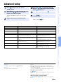
Advanced setup ...................................................45
TROUBLESHOOTING
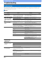
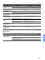
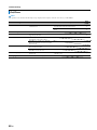
Troubleshooting...................................................46
APPENDIX
Glossary................................................................50
Specifications.......................................................52
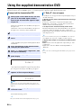
Using the supplied demonstration DVD.............54
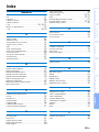
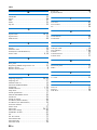
Index......................................................................55
About this manual
• In this manual, operations that can be performed using either the front panel buttons or the remote control are explained using the
remote control.
•
y indicates a tip for your operation.
• Notes contain important information and operating instructions.
• This manual is produced prior to production. Design and specifications are subject to change in part as a result of improvements,
etc. In case of differences between the manual and the product, the product has priority.
• The alphabet mark (such as ) indicates the remote control key(s) indicated on the figure on the left page.

4 En
PREPARATION
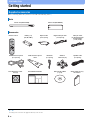
Getting started
Before connecting, make sure you have received all of the following items.
1)
Supplied accessories
Units
Accessories
Center unit (YSP-CU2200) Subwoofer (NS-SWP600)
Remote control Battery (× 2)
(AA, R6, UM-3)
Optical cable
(1.5 m (4.9 ft))
Video pin cable
(for displaying menu
and iPod video)
(1.5 m (4.9 ft))
IR Flasher
(1 m (3.3 ft))
Safety and Accessory
Information
IntelliBeam microphone
(6 m (19.7 ft))
Cardboard microphone
stand
Quick Reference Guide
Digital audio pin cable
(1.5 m (4.9 ft))
Demonstration DVD
(☞p. 54)
Stand for
subwoofer (×4)
Speaker cable
(3 m (9.8 ft))
Non-skid pad for center
unit (×4)
According to the connection, the supplied cables may not be needed.
1) y

5 En
PREPARATION
CONNECTION/
INITIAL SETTINGS PLAYBACK SETTINGS
TROUBLESHOOTING
APPENDIX
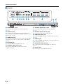
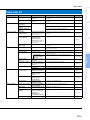
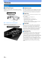
Controls and functions
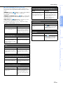
1 Front panel display
Shows information about the operational status of this unit.
(☞p. 7)
2 SURROUND indicator
Lights up according to the input signal.
3 STATUS indicator
Lights up to show the system condition.
4 INTELLIBEAM jack
Connect the supplied IntelliBeam microphone for AUTO SETUP
(☞p. 17).
5 Remote control sensor
Receives infrared signals from the remote control. (☞p. 8)
6 Remote control sensor of a TV
Receives infrared signals from the remote control of your TV
when connecting the IR Flasher. (☞p. 10)
7 INPUT key
Selects playback component. (☞p. 15)
8 VOLUME +/- key
Controls the volume of the unit. (☞p. 26)
9 key
Turns on the unit or set it to the standby mode.
Controls and functions
Front panel
12
3
45 6
789
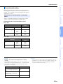
Displayed
color
Input signal
Blue Following surround audio signal formats:
Dolby TrueHD, Dolby Digital Plus, DTS-HD
Master Audio, DTS-HD High Resolution, Multi-
channel Linear PCM
Orange Surround audio signal other than above
Off Audio signal other than above or no signal
Light Power
HDMI
CONTROL
(☞p. 43)
Interlock
Mode
(☞p. 34)
Green On – –
Red Standby On –
Standby – On
Off Standby Off Off
In the standby mode, this unit consumes a small amount of
power in order to receive infrared signals from the remote
control or to search for HDMI signals.
Note

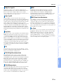
Controls and functions
6 En
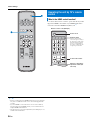
1 AUDIO INPUT 3 jack
For connecting analog cable to the external components.
(☞p. 15)
2 DOCK terminal
For connecting optional Yamaha Universal Dock for iPod,
Wireless System for iPod/iPhone, and Bluetooth Wireless Audio
Receiver. (☞p. 33, 35)
3 VIDEO OUT jack
For connecting video input jack of TV to display the YSP-2200’s
setup menus on your TV or to play back video in iPod/iPhone.
(☞p. 14)
4 IR output jack
For connecting IR Flasher (supplied). (☞p. 11)
5 COAXIAL digital input 2 jack
For connecting digital audio pin cable to the external
components. (☞p. 15)
6 OPTICAL digital input 1 jack
For connecting optical cable to the external components.
(☞p. 15)
7 OPTICAL digital input TV jack
For connecting optical cable to the TV. (☞p. 14)
8 HDMI OUT (ARC) jack
For connecting HDMI compatible TV and external components.
(☞p. 14)
9 HDMI IN jack
For connecting HDMI compatible Blu-ray disc player, tuner and
game console. (☞p. 14, 15)
0 Subwoofer output terminal
For connecting the speaker cable (supplied) to subwoofer.
(☞p. 14)
a Power cable
For connecting to an AC wall outlet. (☞p. 14)
Rear panel
1234567 8 9 0A

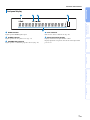
Controls and functions
7 En
PREPARATION
CONNECTION/
INITIAL SETTINGS PLAYBACK SETTINGS
TROUBLESHOOTING
APPENDIX
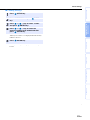
1 HDMI indicator
Lights up when HDMI signal is input.
2 SLEEP indicator
Lights up when the sleep timer is set. (☞p. 32)
3 CINEMA DSP indicator
Lights up when a sound field program is selected (☞p. 28).
4 VOL indicator
Indicates the current volume level. (☞p. 26)
5 Multi information display
Displays information in alpha-numeric values.
Displays playback components and current sound output when
power is on.
Front panel display
12
5
34

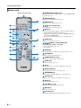
Controls and functions
8 En
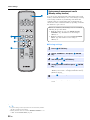
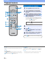
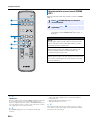
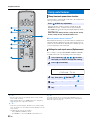
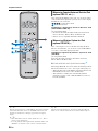
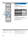
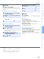
CINEMA DSP program keys
When playback is in surround sound, select the CINEMA DSP
programs (☞p. 28).
SURROUND key
Switches to surround playback. (☞p. 28)
STEREO key
Switches to stereo playback. (☞p. 27)
Input selector keys
Select playback component. (☞p. 26)
INFO key
Switches the information display on the front panel as follows.
• Input/Output: Input name/surround mode
• DSP Program: Sound field program of CINEMA DSP (only
when using CINEMA DSP)
• Audio Decoder: Sound signal decoder currently selected
SETUP key
Displays the setup menu. (☞p. 36)
MENU (U) key, ENTER key,
(Y) key, (Z) key, (V) key
• Change the setting. (☞p. 36)
• Operate iPod.
DOCK key
Selects iPod/iPhone or Bluetooth component. (☞p. 33, 35)
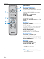
RETURN key
Returns to the previous menu screen.
SUBWOOFER (+/-) key
Adjusts the volume balance of subwoofer.
SLEEP key
Sets the sleep timer. (☞p. 32)
key
Turns on the unit or set it to the standby mode. (☞p. 26)
UNIVOLUME key
Turns UniVolume mode to on/off. (☞p. 27)
ENHANCER key
Turns Compressed Music Enhancer to on/off. (☞p. 27)
OPTION key
Displays option menu for each input source. (☞p. 32)
S/T key
Operate iPod wheel. (☞p. 33).
VOLUME (+/-) key
Controls the volume of the unit. (☞p. 26)
MUTE key
Mute the sound. (☞p. 26)
CH LEVEL key
Adjusts the volume balance during playback. (☞p. 27)
Remote control
Infrared signal transmitter

9 En
CONNECTION/INITIAL SETTINGS
PREPARATION
CONNECTION/
INITIAL SETTINGS PLAYBACK SETTINGS
TROUBLESHOOTING
APPENDIX
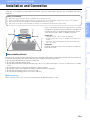
Installation and Connection
To achieve desired surround sound effects, install this unit where there are no objects such as furniture obstructing the path of sound
beams (☞p. 11). Depending on your installation environment, connections with external components (☞p. 14) should be done before
installation.
Some of your TV have sensors such as motion sensor, or signal
transmitter for 3D glasses in front. Installing the center unit may
interrupts the sensors or signal transmitter functioning. Set the
center unit away from your TV, or install it in your rack.
Center unit
• Install this unit in the center of the left and right walls.
• Listening position (such as sofa, etc.) should be located at the front of
the unit.
• The distance between listening position and the unit should be more
than 1.8 m (5.9 ft).
Subwoofer
Install the subwoofer as close to the center unit as possible for a
better unit of sounds.
This unit creates surround sound by reflecting projected sound beams off the walls of your listening room. The surround sound effects
produced by this unit may not be sufficient when this unit is installed in the following locations.
• Rooms with walls inadequate for reflecting sound beams
• Rooms with acoustically absorbent walls
• Rooms with measurements outside the following range: W (3 to 7 m (10 to 23 ft)) × H (2 to 3.5 m (7 to 11.5 ft)) × D (3 to 7 m (10 to
23 ft))
• Rooms with less than 1.8 m (6 ft) from the listening position to this unit
• Rooms where objects such as furniture are likely to obstruct the path of sound beams
• Rooms where the listening position is close to the walls
• Rooms where the listening position is not in front of this unit
■ My Surround
In the room such as above, you can enjoy rich surround effects by My Surround (☞p. 29, 30).
Notes on installation
• Make sure you leave an adequate amount of ventilation space so that heat can escape.
• Be sure to install this unit where it will not fall subject to vibrations, such as from an earthquake, and where it is out of the reach of children.
• When using a cathode-ray tube (CRT) TV, do not install this unit directly above your TV.
• If the picture on your TV screen becomes blurred or distorted, we recommend moving this unit away from your TV.
Center unit
Subwoofer
Before installing this unit

Installation and Connection
10 En
■ Adjust the height of center unit
In case that the center unit straddles the stands of your TV,
turning the stands to left makes the unit higher. Confirm the
graduation of each stand to make each stand the same height.
Adjust the graduation in the range from 0 to 10.
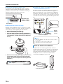
■ Remove the center unit legs
When the center unit hides the remote control sensor or signal
transmitter for 3D glasses of your TV, turn the center unit over,
remove the legs, and use supplied pads as shown below.
1 Turn the leg furthermore to the left.
2 Remove the outside part of the leg.
3 Push the whole leg to the center of the bottom as
shown in the illustration while laying the hook to the
same direction, and then remove the inside part of
the leg.
4 Attach the 4 non-skid pads (supplied) to the corners
on the bottom of the center unit. (The illustration
below is one of the examples for attaching the non-
skid pads.)
■ When the center unit hides the remote
control sensor of your TV
The unit receives the signal from the remote control of your TV
in front, and transmits to your TV by IR Flasher (supplied).
Remove the backing paper on the tip of LED part of IR Flasher,
and attach it to the remote control sensor of your TV or the area
close to the remote control sensor of your TV on the rear panel of
center unit as shown. Connect the plug to the IR output jack of the
unit.
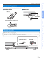
Install the subwoofer with the supplied stands. Attach the
supplied stands with the dowels to the subwoofer. Changing the
position of the stands enables both horizontal placement and
vertical placement. Horizontal placement is convenient for
installing the center of a rack, and vertical placement is
convenient for installing the side of a rack.
The graduation
Adjustable range:
28.5mm to 38.5mm
(1-1/8 in to 1-1/2 in)
Non-skid pad
Attach the stands to the subwoofer
IR Flasher (supplied)
Remote
control
sensor of
your TV
• When using IR Flasher, direct the remote control of your TV to
the center unit.
• This function is valid even in the standby mode.
• This function may not activate with some TVs.
Notes
Horizontal placement Vertical
placement

Installation and Connection
11 En
PREPARATION
CONNECTION/
INITIAL SETTINGS PLAYBACK SETTINGS
TROUBLESHOOTING
APPENDIX
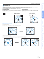
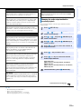
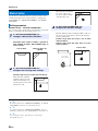
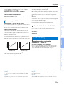
This unit outputs sound beam as shown in the illustrations below. Install this unit where there are no obstacles such as furniture
obstructing the path of sound beams. Otherwise, the desired surround sound effects may not be achieved.
You may install this unit in parallel with the wall or in the corner.
■ Installation examples
Parallel installation
Install this unit as close to the exact center of the wall as possible.
Ideal installation condition
Install this unit as close to the exact front of your normal listening position as possible.
The distance between listening position and the unit should be more than 1.8 m (6 ft).
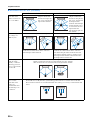
Installing this unit
Parallel installation
Install this unit in the exact center of the wall when it is measured
from the left and right corners.
Corner installation
Install this unit in the corner at a 40° to 50° angle from the
adjacent walls.
An object, such as furniture
40° to 50°
Parallel installation
(with 5Beam)
Corner installation
(with Stereo+3Beam)

Installation and Connection
12 En
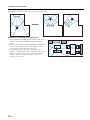
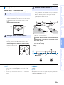
Installing in a non-square room
Install this unit so that the sound beams can be reflected off the walls.
Example for installing the unit in living room
• As surround beams normally pass through tables, tables are not
obstacles. And a cupboard installed facing the wall reflects
sounds.
• In a case of the listening room as right illustration, adjusting the
position of right channel after auto setup enables to achieve
more desired surround sound effects. (☞p. 38)
• As the curtains absorb sounds, the sound features of the
listening room is different from the case with the curtain opened
and the case with the curtain closed. Using saving settings
function enables to save the best settings for each case of
listening room. (☞p. 22)

Installation and Connection
13 En
PREPARATION
CONNECTION/
INITIAL SETTINGS PLAYBACK SETTINGS
TROUBLESHOOTING
APPENDIX
Before installing batteries or using the remote control, make sure that you read precautions on the remote control and batteries in
“CAUTION: READ THIS BEFORE OPERATING YOUR UNIT.”
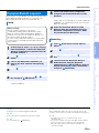
Remote control preparation
Installing the batteries
Battery × 2
(AA, R6, UM-3)
Press U
Remove the transparent sheet before using.
Operation range
Within 6 m (20 ft)
Subwoofer connection
• Make sure to connect the subwoofer (supplied).
• Do not connect a subwoofer except the supplied one.
• Match the positive (+) of the subwoofer terminal to the positive (+) of the center unit terminal, and the negative (-) of the subwoofer terminal to
the negative (-) of the center unit terminal when connecting the speaker cable (supplied).
Twist and pull off the
insulation tube on the lead
wire.
Insert into the terminal on
the rear panel.

14 En
Connections
For the cable connection, follow the orders below.
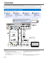
TV and Blu-ray disc player connection
1
HDMI cable
(optional)
Input the digital audio/
video signals of the Blu-
ray disc player to this
unit.
2
HDMI cable
(optional)
The digital video of the
Blu-ray disc is reflected
on TV.
3
Optical cable
(supplied)
Play back digital sounds
of TV on this unit.
4
Video pin cable
(supplied)
To display the YSP-
2200’s setup menus on
the TV.
• Do not connect the power cable until all connections are completed.
• Do not use excessive force when inserting the cable plug. Doing so may damage the cable plug and/or terminal.
123
INPUT1
HDMI INPUT
OPTICAL
OUTPUT
VIDEO
AUDIORL
HDMI
OUTPUT
To AC wall outlet
Blu-ray disc player
1. Remove the cap
2. Check the direction
of the plug
TV
Video signals
Audio signals
1
2
3
(Example)
1)
4
Subwoofer (supplied)
5
Connect the center unit with the speaker cable
(supplied) to the subwoofer. (☞p. 13).
2)
Audio return channel (ARC) supported TV
• Connect HDMI cable to audio return channel supported terminal (the
terminal with “ARC” indicated) on TV. In this case, you do not need
to connect optical cable.
• Activate the HDMI control function of this unit so as to activate audio
return channel (ARC) (☞p. 43).
What is audio return channel (ARC)?
A function transmits digital audio signal output from TV to this unit
through a HDMI cable. By this function, a digital audio pin cable to
connect TV and this unit is not needed.
Depending on the setting, HDMI for video signal and optical digital
audio, coaxial digital audio or analog audio for audio signal can be
selected. Refer to “Input assignment (☞p. 42)”.
1) y
2) y

15 En
Connections
PREPARATION
CONNECTION/
INITIAL SETTINGS PLAYBACK SETTINGS
TROUBLESHOOTING
APPENDIX
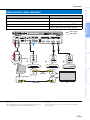
Game console or tuner connection
Additional external device (example) Connecting cable
1 HDMI supported game console
HDMI cable (optional)
2 Satellite/cable TV (HDMI supported)
HDMI cable (optional)
3 Satellite/cable TV (HDMI not supported)
Digital audio pin cable (supplied)
4)
4 HDMI not supported game console
Analog audio stereo pin cable (optional)
4)
ANALOG
OUTPUT
COAXIAL
OUTPUT
HDMI
OUTPUT
HDMI
OUTPUT
VIDEO
INPUT
VIDEO
INPUT
VIDEO
OUTPUT
VIDEO
OUTPUT
Video signals
Audio signals
TV
1
4
3)
(Example)
4)
(Example)
2 3
(Example)
4)
(Example)
The additional devices having an optical digital output jack, connect to
the optical digital input jack of this unit with an optical cable.
To connect a game console or tuner to TV, you need extra video pin
cables (optional).
3) y 4) y

16 En
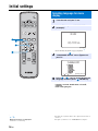
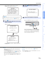
Initial settings
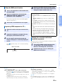
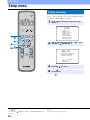
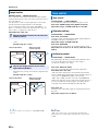
Selecting language for menu
display
1
Turn the unit and your TV on.
2
Switch TV’s input to “VIDEO INPUT 1
(example)”.
Check whether the initial screen is displayed.
1)
3
Press and hold SETUP key until the
“LANGUAGE SETUP” menu appears on
your TV.
4
Press U / V key to select the desired
language and then press ENTER key.
Selectable item: ENGLISH, DEUTSCH, FRANÇAIS,
ESPAÑOL, ITALIANO, NEDERLANDS, РУССКИЙ,
SVENSKA
Initial setting: English
YSP-2200
Push [SETUP] to
begin SETUP MENU.
(example)
[ ]/[ ]:Sel [ENTER]:Return
3)LANGUAGE SETUP
When the screen is not displayed
Confirm the case followings.
– The input jack of your TV and the video output jack of the unit are
connected.
– The input of your TV is set to “VIDEO INPUT 1 (example)”.
1) y

17 En
Initial settings
PREPARATION
CONNECTION/
INITIAL SETTINGS PLAYBACK SETTINGS
TROUBLESHOOTING
APPENDIX
This unit creates a sound field by reflecting sound beams on the
walls of your listening room and by broadening the cohesion of
all the channels. Just as you would arrange the speaker position of
other audio systems, you need to set the beam angle to enjoy the
best possible sound from this unit.
This unit employs the beam optimization and sound optimization
features with the aid of the supplied IntelliBeam microphone, allowing
you to avoid troublesome listening-based setup and achieving highly
accurate sound adjustments that best match your listening
environment. We call these two features “IntelliBeam” generically.
Beam optimization:
This feature optimizes the beam angle so that the parameter best
matches your listening environment.
Sound optimization:
This feature optimizes the beam delay, volume, and quality so
that the parameters best match your listening environment.
This unit performs these two automatic optimizations with the aid
of the supplied IntelliBeam microphone.
2)
Auto setup for appropriate
surround effects (IntelliBeam)
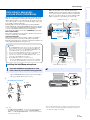
Installing the IntelliBeam microphone
1
Place the IntelliBeam microphone on a flat
level surface at your normal listening position.
Use the supplied cardboard microphone stand or a tripod
to place the IntelliBeam microphone at the same height as
your ears would be when you are seated.
■ Assembling the supplied cardboard
microphone stand
• The AUTO SETUP procedure may not be run successfully if this
unit is installed in one of the rooms described in “Installing this
unit” on page 11. In such cases, run MANUAL SETUP (☞p. 20)
to manually adjust the corresponding parameters.
• Do not connect the IntelliBeam microphone to an extension cable
as doing so may result in an inaccurate sound optimization.
• After you have completed the AUTO SETUP procedure, be sure
to disconnect the IntelliBeam microphone.
• The IntelliBeam microphone is sensitive to heat.
– Keep the IntelliBeam microphone away from direct sunlight.
– Do not place the IntelliBeam microphone on top of this unit.
Notes
1 2 3
54
Remove
Fit in
Run
through
Place
horizontally
Fit in
Make sure that there are no obstacles between the
IntelliBeam microphone and the walls in your listening
room as these objects obstruct the path of sound beams.
However, any objects that are in contact with the walls
will be regarded as a protruding part of the walls.
2
Check if a video pin cable is connected.
IntelliBeam microphone Upper limit
Within 1 m (3.3 ft)
Center height of this
unit
Cardboard microphone
stand
Within 1 m (3.3 ft)
Listening
position
1.8 m (6.0 ft)
or more
Lower limit
Center line
IntelliBeam
microphone
Cardboard microphone stand
• “BEAM+SOUND OPTIMIZE” screen appears automatically when
the IntelliBeam microphone is connected. “BEAM OPTIMIZE
ONLY” or “SOUND OPTIMIZE ONLY” can be selected separately
in setup menu (☞p. 20).
• Data set automatically can be saved in the system memory (☞p. 22).
You can save the several data depending on listening room and you
can change the setting conveniently.
2) y

Initial settings
18 En
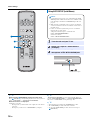
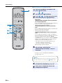
Using AUTO SETUP (IntelliBeam)
1
Turn the unit and your TV on.
2
Switch TV’s input to “VIDEO INPUT 1
(example)”.
3
Connect the supplied IntelliBeam
microphone to the INTELLIBEAM jack.
• It is normal for loud test tones to be output during the AUTO
SETUP procedure. Make sure that there are no children around
in the listening room while the AUTO SETUP procedure is in
progress.
• Make sure that your listening room is as quiet as possible. For
accurate measurement, turn off air conditioner or other devices
that make noises.
• If there are curtains in your listening room, we recommend
following the procedure below.
1 Open the curtains to improve sound reflection.
2 Run “BEAM OPTIMIZE ONLY”.
3 Close the curtains.
4 Run “SOUND OPTIMIZE ONLY”.
Notes
IntelliBeam microphone
When pressing RETURN key displays the setup menu
Press SETUP key repeatedly and display the menu screen again, then
select: “AUTO SETUP” “BEAM+SOUND OPTIMIZE”.
When the screen is not displayed
Confirm the case below.
– The input jack of your TV and the video output jack of the unit are
connected.
– The input of your TV is set to “VIDEO INPUT 1 (example)”.
“BEAM+SOUND OPTIMIZE” is selected automatically. When you
perform “BEAM OPTIMIZE ONLY” or “SOUND OPTIMIZE ONLY”
only, refer to “AUTO SETUP via setup menu (☞p. 20)”.
• Wait outside the room during the AUTO SETUP procedure.
• The AUTO SETUP procedure takes about 3 minutes.
• To cancel the AUTO SETUP procedure after it is started, press
RETURN key.
1) y 2) y
3) y
Sayfa yükleniyor...
Sayfa yükleniyor...
Sayfa yükleniyor...
Sayfa yükleniyor...
Sayfa yükleniyor...
Sayfa yükleniyor...
Sayfa yükleniyor...
Sayfa yükleniyor...
Sayfa yükleniyor...
Sayfa yükleniyor...
Sayfa yükleniyor...
Sayfa yükleniyor...
Sayfa yükleniyor...
Sayfa yükleniyor...
Sayfa yükleniyor...
Sayfa yükleniyor...
Sayfa yükleniyor...
Sayfa yükleniyor...
Sayfa yükleniyor...
Sayfa yükleniyor...
Sayfa yükleniyor...
Sayfa yükleniyor...
Sayfa yükleniyor...
Sayfa yükleniyor...
Sayfa yükleniyor...
Sayfa yükleniyor...
Sayfa yükleniyor...
Sayfa yükleniyor...
Sayfa yükleniyor...
Sayfa yükleniyor...
Sayfa yükleniyor...
Sayfa yükleniyor...
Sayfa yükleniyor...
Sayfa yükleniyor...
Sayfa yükleniyor...
Sayfa yükleniyor...
Sayfa yükleniyor...
Sayfa yükleniyor...
Sayfa yükleniyor...
-
 1
1
-
 2
2
-
 3
3
-
 4
4
-
 5
5
-
 6
6
-
 7
7
-
 8
8
-
 9
9
-
 10
10
-
 11
11
-
 12
12
-
 13
13
-
 14
14
-
 15
15
-
 16
16
-
 17
17
-
 18
18
-
 19
19
-
 20
20
-
 21
21
-
 22
22
-
 23
23
-
 24
24
-
 25
25
-
 26
26
-
 27
27
-
 28
28
-
 29
29
-
 30
30
-
 31
31
-
 32
32
-
 33
33
-
 34
34
-
 35
35
-
 36
36
-
 37
37
-
 38
38
-
 39
39
-
 40
40
-
 41
41
-
 42
42
-
 43
43
-
 44
44
-
 45
45
-
 46
46
-
 47
47
-
 48
48
-
 49
49
-
 50
50
-
 51
51
-
 52
52
-
 53
53
-
 54
54
-
 55
55
-
 56
56
-
 57
57
-
 58
58
-
 59
59


Yamaha NS-SWP600 Kullanım kılavuzu
- Kategori
- Alıcı
- Tip
- Kullanım kılavuzu
diğer dillerde
- español: Yamaha NS-SWP600 Manual de usuario
- français: Yamaha NS-SWP600 Manuel utilisateur
- italiano: Yamaha NS-SWP600 Manuale utente
- svenska: Yamaha NS-SWP600 Användarmanual
- Deutsch: Yamaha NS-SWP600 Benutzerhandbuch
- English: Yamaha NS-SWP600 User manual
- dansk: Yamaha NS-SWP600 Brugermanual
- русский: Yamaha NS-SWP600 Руководство пользователя
- Nederlands: Yamaha NS-SWP600 Handleiding
- română: Yamaha NS-SWP600 Manual de utilizare