Makita LS1019 Slide Compound Miter Saw Kullanım kılavuzu
- Tip
- Kullanım kılavuzu

LS1019
LS1019L
EN Slide Compound Miter Saw INSTRUCTION MANUAL 14
FR Scie à Onglet Radiale MANUEL D’INSTRUCTIONS 28
DE Kapp- und Gehrungssäge BETRIEBSANLEITUNG 44
IT Troncatrice composita a slitta ISTRUZIONI PER L’USO 61
NL Schuifbare afkortverstekzaag GEBRUIKSAANWIJZING 78
ES Sierra de Inglete Telescópica MANUAL DE
INSTRUCCIONES 95
PT Serra de Esquadria c/ Braço
Telescópico MANUAL DE INSTRUÇÕES 112
DA Kombineret
afkorter-geringssav BRUGSANVISNING 128
EL Ολισθαίνον πριόνι σύνθετης
λοξότμησης ΕΓΧΕΙΡΙΔΙΟ ΟΔΗΓΙΩΝ 143
TR Kızaklı Birleşik Gönyeburun
Testere KULLANMA KILAVUZU 161

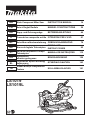
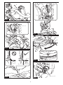
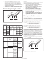
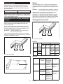
Fig.1
10 11
12
14
15
3
2
4
5
879
13
6
1
16
17
18
19
20 21
Fig.2
2

7 8
5
6
1
2
34
9
10
11
141312
15
Fig.3
1
2
Fig.4
1
2
3
4
4
Fig.5
3

3
12
Fig.6
1
Fig.7
1
Fig.8
3
1
2
Fig.9
1
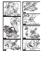
Fig.10
1
23
4
6
5
Fig.11
4

1
Fig.12
1
Fig.13
1
23
Fig.14
1
2
Fig.15
1
2
3
4
Fig.16
1
Fig.17
5

1
Fig.18
1
2
Fig.19
1
Fig.20
1
Fig.21
1
Fig.22
3
1
2
Fig.23
1
2
3
Fig.24
6

1
Fig.25
1
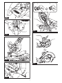
Fig.26
A
B
Fig.27
1
Fig.28
12
3
Fig.29
3
1
2
Fig.30
7

1
2
4
5
3
Fig.31
1
2
Fig.32
1 2 345
6
Fig.33
1 2
3
Fig.34
1
2
Fig.35
1
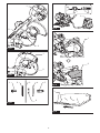
Fig.36
8

12
Fig.37
1
2
3
1
2
3
4
4
Fig.38
1 2
3
Fig.39
1
2
3
4
Fig.40
1
2 3
Fig.41
1
2
Fig.42
9

1
Fig.43
1
Fig.44
Fig.45
123
Fig.46
2
3
1
4
Fig.47
1
2
3
4
Fig.48
10

1
2
34
Fig.49
1
2
Fig.50
1
5
3
4
2
Fig.51
1
Fig.52
Fig.53
2
1
2
3
Fig.54
1
Fig.55
11

1
2
Fig.56
1
2
3
Fig.57
Fig.58
1
2
Fig.59
1
2
3
4
5
Fig.60
12

1
2
3
4
5
Fig.61
1
2
Fig.62
1
Fig.63
1
Fig.64
13

14 ENGLISH
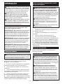
ENGLISH (Original instructions)
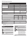
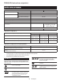
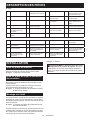
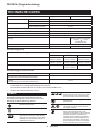
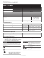
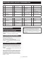
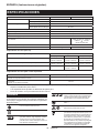
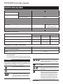
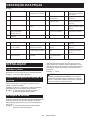
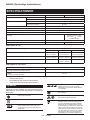
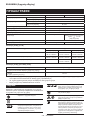
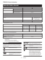
SPECIFICATIONS
Model: LS1019 LS1019L
Blade diameter European countries 260 mm
Countries other than Europe 255 mm - 260 mm
Hole diameter European countries 30 mm
Countries other than Europe 25.4 mm
Max. kerf thickness of the saw blade 3.2 mm
Max. miter angle Right 60°, Left 60°
Max. bevel angle Right 48°, Left 48°
No load speed (RPM) 3,200 min-1
Laser type -Red Laser 650 nm, Maximum
output 1.6mW
( Laser Class 2M )
Dimensions (L x W x H) 805 mm x 644 mm x 660 mm
Net weight 26.1 kg 26.3 kg
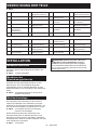
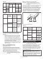
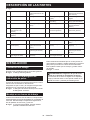
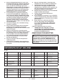
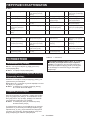
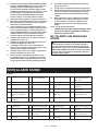
Cutting capacities (H x W)
Miter angle Bevel angle
45° (left) 0° 45° (right)
0° 42 mm x 310 mm
58 mm x 279mm
68 mm x 310 mm
91 mm x 279 mm
29 mm x 310 mm
43 mm x 279 mm
45° (right and left) 42 mm x 218 mm
58 mm x 197 mm
68 mm x 218 mm
91 mm x 197 mm
29 mm x 218 mm
43 mm x 197 mm
60° (right and left) -68 mm x 155 mm
91 mm x 139 mm
-
Cutting capacities for special cuttings
Type of cutting Cutting capacity
Crown molding 45° type
(with crown molding stopper used)
168 mm
Base board
(with horizontal vise used)
133 mm
• Duetoourcontinuingprogramofresearchanddevelopment,thespecicationshereinaresubjecttochange
without notice.
• Specicationsmaydifferfromcountrytocountry.
• Weight according to EPTA-Procedure 01/2014
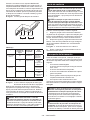
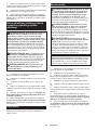
Symbols
The following show the symbols used for the equip-
ment. Be sure that you understand their meaning before
use.
Read instruction manual.
DOUBLE INSULATION
Toavoidinjuryfromyingdebris,keep
holding the saw head down, after making
cuts, until the blade has come to a com-
plete stop.
Whenperformingslidecut,rstpullcar-
riage fully and press down handle, then
push carriage toward the guide fence.
Donotplacehandorngersclosetothe
blade.
Never look into the laser beam. Direct laser
beammayinjureyoureyes.
Only for EU countries
Do not dispose of electric equipment
together with household waste material! In
observance of the European Directive, on
Waste Electric and Electronic Equipment
and its implementation in accordance with
national law, electric equipment that have
reached the end of their life must be col-
lected separately and returned to an envi-
ronmentally compatible recycling facility.

15 ENGLISH
Intended use
The tool is intended for accurate straight and miter
cutting in wood. With appropriate saw blades, aluminum
can also be sawed.
Power supply
The tool should be connected only to a power supply of
the same voltage as indicated on the nameplate, and
can only be operated on single-phase AC supply. They
are double-insulated and can, therefore, also be used
from sockets without earth wire.
Noise
The typical A-weighted noise level determined accord-
ing to EN62841:
Model LS1019
Sound pressure level (LpA) : 91 dB(A)
Sound power level (LWA) : 101 dB (A)
Uncertainty (K) : 3 dB(A)
Model LS1019L
Sound pressure level (LpA) : 91 dB(A)
Sound power level (LWA) : 101 dB (A)
Uncertainty (K) : 3 dB(A)
WARNING: Wear ear protection.
Vibration
The vibration total value (tri-axial vector sum) deter-
mined according to EN62841:
Model LS1019
Vibration emission (ah) : 2.5 m/s2 or less
Uncertainty (K) : 1.5 m/s2
Model LS1019L
Vibration emission (ah) : 2.5 m/s2 or less
Uncertainty (K) : 1.5 m/s2
NOTE: The declared vibration emission value has
been measured in accordance with the standard test
method and may be used for comparing one tool with
another.
NOTE: The declared vibration emission value
may also be used in a preliminary assessment of
exposure.
WARNING: The vibration emission during actual
use of the power tool can differ from the declared
emission value depending on the ways in which the
tool is used.
WARNING: Be sure to identify safety measures
to protect the operator that are based on an estima-
tion of exposure in the actual conditions of use (taking
account of all parts of the operating cycle such as
the times when the tool is switched off and when it is
running idle in addition to the trigger time).
EC Declaration of Conformity
For European countries only
The EC declaration of conformity is included as Annex A
to this instruction manual.
SAFETY WARNINGS
General power tool safety warnings
WARNING: Read all safety warnings, instruc-
tions, illustrations and specications provided
with this power tool. Failure to follow all instructions
listedbelowmayresultinelectricshock,reand/or
seriousinjury.
Save all warnings and instruc-
tions for future reference.
The term "power tool" in the warnings refers to your
mains-operated (corded) power tool or battery-operated
(cordless) power tool.
Safety instructions for mitre saws
1. Mitre saws are intended to cut wood or wood-
like products, they cannot be used with abra-
sive cut-off wheels for cutting ferrous material
such as bars, rods, studs, etc. Abrasive dust
causes moving parts such as the lower guard to
jam.Sparksfromabrasivecuttingwillburnthe
lower guard, the kerf insert and other plastic parts.
2. Use clamps to support the workpiece when-
ever possible. If supporting the workpiece
by hand, you must always keep your hand at
least 100 mm from either side of the saw blade.
Do not use this saw to cut pieces that are too
small to be securely clamped or held by hand.
If your hand is placed too close to the saw blade,
thereisanincreasedriskofinjuryfromblade
contact.
3. The workpiece must be stationary and
clamped or held against both the fence and the
table. Do not feed the workpiece into the blade
or cut "freehand" in any way. Unrestrained
or moving workpieces could be thrown at high
speeds,causinginjury.
4. Push the saw through the workpiece. Do not
pull the saw through the workpiece. To make
a cut, raise the saw head and pull it out over
the workpiece without cutting, start the motor,
press the saw head down and push the saw
through the workpiece. Cutting on the pull stroke
is likely to cause the saw blade to climb on top
of the workpiece and violently throw the blade
assembly towards the operator.
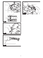
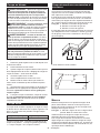
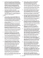
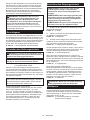
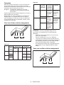
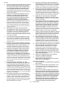
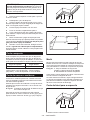
5. Never cross your hand over the intended line
of cutting either in front or behind the saw
blade. Supporting the workpiece "cross handed"
i.e. holding the workpiece to the right of the saw
blade with your left hand or vice versa is very
dangerous.
►Fig.1
6. Do not reach behind the fence with either hand
closer than 100 mm from either side of the saw
blade, to remove wood scraps, or for any other
reason while the blade is spinning. The proxim-
ity of the spinning saw blade to your hand may not
beobviousandyoumaybeseriouslyinjured.

16 ENGLISH
7. Inspect your workpiece before cutting. If the
workpiece is bowed or warped, clamp it with
the outside bowed face toward the fence.
Always make certain that there is no gap
between the workpiece, fence and table along
the line of the cut. Bent or warped workpieces
can twist or shift and may cause binding on the
spinning saw blade while cutting. There should be
nonailsorforeignobjectsintheworkpiece.
8. Do not use the saw until the table is clear of all
tools, wood scraps, etc., except for the work-
piece. Small debris or loose pieces of wood or
otherobjectsthatcontacttherevolvingbladecan
be thrown with high speed.
9.
Cut only one workpiece at a time. Stacked multiple
workpieces cannot be adequately clamped or braced
and may bind on the blade or shift during cutting.
10. Ensure the mitre saw is mounted or placed on
a level, rm work surface before use. A level
andrmworksurfacereducestheriskofthemitre
saw becoming unstable.
11.
Plan your work. Every time you change the bevel
or mitre angle setting, make sure the adjustable
fence is set correctly to support the workpiece
and will not interfere with the blade or the guard-
ing system. Without turning the tool "ON" and with
no workpiece on the table, move the saw blade
through a complete simulated cut to assure there will
be no interference or danger of cutting the fence.
12. Provide adequate support such as table exten-
sions, saw horses, etc. for a workpiece that is
wider or longer than the table top. Workpieces
longer or wider than the mitre saw table can tip
if not securely supported. If the cut-off piece or
workpiece tips, it can lift the lower guard or be
thrown by the spinning blade.
13.
Do not use another person as a substitute for a
table extension or as additional support. Unstable
support for the workpiece can cause the blade to bind
or the workpiece to shift during the cutting operation
pulling you and the helper into the spinning blade.
14.
The cut-off piece must not be jammed or pressed
by any means against the spinning saw blade. If
conned,i.e.usinglengthstops,thecut-offpiececould
get wedged against the blade and thrown violently.
15. Always use a clamp or a xture designed to
properly support round material such as rods
or tubing. Rods have a tendency to roll while
being cut, causing the blade to "bite" and pull the
work with your hand into the blade.
16. Let the blade reach full speed before contact-
ing the workpiece. This will reduce the risk of the
workpiece being thrown.
17. If the workpiece or blade becomes jammed,
turn the mitre saw off. Wait for all moving
parts to stop and disconnect the plug from
the power source and/or remove the battery
pack. Then work to free the jammed material.
Continuedsawingwithajammedworkpiececould
cause loss of control or damage to the mitre saw.
18. After nishing the cut, release the switch,
hold the saw head down and wait for the blade
to stop before removing the cut-off piece.
Reaching with your hand near the coasting blade
is dangerous.
19.
Hold the handle rmly when making an incom-
plete cut or when releasing the switch before the
saw head is completely in the down position. The
braking action of the saw may cause the saw head to
besuddenlypulleddownward,causingariskofinjury.
20. Only use the saw blade with the diameter that
is marked on the tool or specied in the man-
ual. Use of an incorrectly sized blade may affect
the proper guarding of the blade or guard opera-
tionwhichcouldresultinseriouspersonalinjury.
21.
Only use the saw blades that are marked with a speed
equal or higher than the speed marked on the tool.
22. Do not use the saw to cut other than wood,
aluminum or similar materials.
23. (For European countries only)
Always use the blade which conforms to EN847-1.
Additional instructions
1. Make workshop kid proof with padlocks.
2. Never stand on the tool.Seriousinjurycould
occur if the tool is tipped or if the cutting tool is
unintentionally contacted.
3. Never leave the tool running unattended. Turn
the power off. Do not leave tool until it comes
to a complete stop.
4.
Do not operate saw without guards in place.
Check blade guard for proper closing before
each use. Do not operate saw if blade guard does
not move freely and close instantly. Never clamp
or tie the blade guard into the open position.
5.
Keep hands out of path of saw blade. Avoid contact
with any coasting blade. It can still cause severe injury.
6. Never clamp or tie the blade guard into the
open position.
7.
To reduce the risk of injury, return carriage to the
full rear position after each crosscut operation.
8. Always secure all moving portions before
carrying the tool.
9. Stopper pin which locks the cutter head down
is for carrying and storage purposes only and
not for any cutting operations.
10.
Check the blade carefully for cracks or damage
before operation. Replace cracked or damaged
blade immediately. Gum and wood pitch hardened
on blades slows saw and increases potential for
kickback. Keep blade clean by rst removing it from
tool, then cleaning it with gum and pitch remover, hot
water or kerosene. Never use gasoline to clean blade.
11. While making a slide cut, KICKBACK can
occur. KICKBACK occurs when the blade
binds in the workpiece during a cutting oper-
ation and the saw blade is driven rapidly
towards the operator. Loss of control and seri-
ous personal injury can result. If blade begins
to bind during a cutting operation, do not con-
tinue to cut and release switch immediately.
12. Use only anges specied for this tool.
13.
Be careful not to damage the arbor, anges
(especially the installing surface) or bolt. Damage
to these parts could result in blade breakage.
14. Make sure that the turn base is properly
secured so it will not move during operation.
Use the holes in the base to fasten the saw to a
stable work platform or bench. NEVER use tool
where operator positioning would be awkward.

17 ENGLISH
15. Make sure the shaft lock is released before the
switch is turned on.
16. Be sure that the blade does not contact the
turn base in the lowest position.
17.
Hold the handle rmly. Be aware that the saw moves
up or down slightly during start-up and stopping.
18. Make sure the blade is not contacting the
workpiece before the switch is turned on.
19.
Before using the tool on an actual workpiece, let it run
for a while. Watch for vibration or wobbling that could
indicate poor installation or a poorly balanced blade.
20. Stop operation immediately if you notice any-
thing abnormal.
21.
Do not attempt to lock the trigger in the "ON" position.
22. Always use accessories recommended in this
manual. Use of improper accessories such as
abrasive wheels may cause an injury.
23. Some material contains chemicals which may
be toxic. Take caution to prevent dust inhala-
tion and skin contact. Follow material supplier
safety data.
Additional safety rules for the laser
1. LASER RADIATION, DO NOT STARE INTO THE
BEAM OR VIEW DIRECTLY WITH OPTICAL
INSTRUMENTS, CLASS 2M LASER PRODUCT.
SAVE THESE INSTRUCTIONS.
WARNING: DO NOT let comfort or familiarity
with product (gained from repeated use) replace
strict adherence to safety rules for the subject
product. MISUSE or failure to follow the safety
rules stated in this instruction manual may cause
serious personal injury.
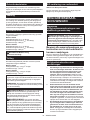
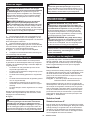
PARTS DESCRIPTION
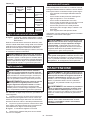
►Fig.2
1Slide pole 2Stopper pin (for carriage
sliding)
3Vertical vise 4Releasing button (for
right side bevel angle)
5Holder 6Turn base 7Pointer (for miter angle) 8Miter angle scale
9Kerf board 10 Blade case 11 Adjustingscrew(for
laser line)
12 Rangeadjustmentscrew
(for laser line)
13 Blade guard 14 Knob (for bevel angle) 15 Hex wrench 16 Adjustingscrew(for
lower limit position)
17 Adjustingbolt(formaxi-
mum cutting capacity)
18 Stopper arm 19 Lock lever (for turn base) 20 Releasing lever (for turn
base)
21 Grip (for turn base) ------
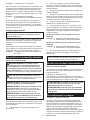
►Fig.3
1Switch trigger 2Lock-off button 3Hole for padlock 4Switch (for laser line)
5Hose (for dust
extraction)
6Stopper pin (for carriage
elevation)
7Guide fence (lower
fence)
8Guide fence (upper
fence)
9Dust bag 10 0°adjustingbolt(for
bevel angle)
11 Bevel angle scale 12 Releasing lever (for 48°
bevel angle)
13 Latch lever (for bevel
angle)
14 Pointer (for bevel angle) 15 45°adjustingbolt(for
bevel angle)
- -
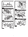
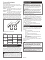
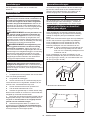
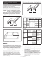
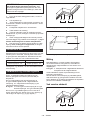
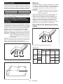
INSTALLATION
Installing the grip
Screw the threaded shaft of the grip into the turn base.
►Fig.4: 1. Grip 2. Turn base
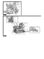
Installing the dust extraction hose
Connect the dust extraction hose to the tool as
illustrated.
Makesurethattheelbowandthesleevetproperlyto
the ports of the tool.
►Fig.5: 1. Dust extraction hose 2. Elbow 3. Sleeve
4. Port
Bench mounting
When the tool is shipped, the handle is locked in the
lowered position by the stopper pin. While lowering the
handle slightly, pull the stopper pin and rotate it 90°.
►Fig.6: 1. Locked position 2. Unlocked position
3. Stopper pin
This tool should be bolted with four bolts to a level and
stable surface using the bolt holes provided in the tool's
base.Thiswillhelppreventtippingandpossibleinjury.
►Fig.7: 1. Bolt
WARNING: Ensure that the tool will not move
on the supporting surface. Movement of the miter
saw on the supporting surface while cutting may
resultinlossofcontrolandseriouspersonalinjury.

18 ENGLISH
FUNCTIONAL
DESCRIPTION
WARNING: Always be sure that the tool is
switched off and unplugged before adjusting or
checking function on the tool. Failure to switch off
and unplug the tool may result in serious personal
injuryfromaccidentalstart-up.
Blade guard
►Fig.8: 1. Blade guard
When lowering the handle, the blade guard rises auto-
matically. The guard is spring loaded so it returns to
its original position when the cut is completed and the
handle is raised.
WARNING: Never defeat or remove the blade
guard or the spring which attaches to the guard.
An exposed blade as a result of defeated guarding
mayresultinseriouspersonalinjuryduringoperation.
In the interest of your personal safety, always maintain
the blade guard in good condition. Any irregular opera-
tion of the blade guard should be corrected immediately.
Check to assure spring loaded return action of guard.
WARNING: Never use the tool if the blade
guard or spring are damaged, faulty or removed.
Operation of the tool with a damaged, faulty or
removedguardmayresultinseriouspersonalinjury.
If the see-through blade guard becomes dirty, or saw-
dust adheres to it in such a way that the blade and/or
workpiece is no longer easily visible, unplug the saw and
clean the guard carefully with a damp cloth. Do not use
solvents or any petroleum-based cleaners on the plastic
guard because this may cause damage to the guard.
If the blade guard is especially dirty and vision through
the guard is impaired, unplug the tool and use the sup-
plied wrench to loosen the hex bolt holding the center
cover. Loosen the hex bolt by turning it counterclock-
wise and raise the blade guard and center cover. With
the blade guard so positioned, cleaning can be more
completelyandefcientlyaccomplished.Whencleaning
is complete, reverse procedure above and secure bolt.
Do not remove spring holding blade guard. If guard
becomes discolored through age or UV light exposure,
contact a Makita service center for a new guard. DO
NOT DEFEAT OR REMOVE GUARD.
►Fig.9: 1. Center cover 2. Hex wrench 3. Blade
guard
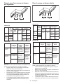
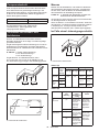
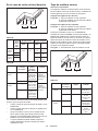
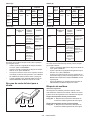
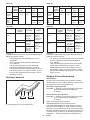
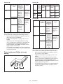
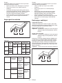
Kerf boards
This tool is provided with the kerf boards in the turn
base to minimize tearing on the exit side of a cut. The
kerfboardsarefactoryadjustedsothatthesawblade
doesnotcontactthekerfboards.Beforeuse,adjustthe
kerf boards as follows:
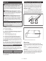
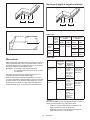
►Fig.10: 1. Kerf board
►Fig.11: 1. Left bevel cut 2. Straight cut 3. Right
bevel cut 4. Saw blade 5. Blade teeth
6. Kerf board
First, unplug the tool. Loosen all the screws (2 each
on left and right) securing the kerf boards until the kerf
boards can still be easily moved by hand. Lower the
handle fully, then pull and turn the stopper pin to lock
the handle in the lowered position. Release the stopper
pin on the sliding pole and pull the carriage toward you
fully.Adjustthekerfboardssothatthekerfboardsjust
contact the sides of the blade teeth. Tighten the front
screws(donottightenrmly).Pushthecarriagetoward
theguidefencefullyandadjustthekerfboardssothat
thekerfboardsjustcontactthesidesofbladeteeth.
Tightentherearscrews(donottightenrmly).
Afteradjustingthekerfboards,releasethestopperpin
and raise the handle. Then tighten all the screws securely.
NOTICE: After setting the bevel angle ensure
that the kerf boards are adjusted properly. Correct
adjustmentofthekerfboardswillhelpprovideproper
support of the workpiece minimizing workpiece tear
out.
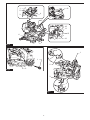
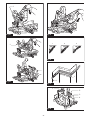
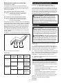
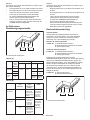
Maintaining maximum cutting
capacity
Thistoolisfactoryadjustedtoprovidethemaximum
cutting capacity for 255 mm or 260 mm saw blade.
When installing a new blade, always check the lower limit
positionofthebladeandifnecessary,adjustitasfollows:
First, unplug the tool. Turn the stopper lever to engaged
position.
►Fig.12: 1. Stopper lever
Push the carriage toward the guide fence fully and
lower the handle completely.
Adjustthebladepositionbyturningtheadjustingbolt
with the hex wrench. The periphery of the blade should
extend slightly below the top surface of the turn base
and also comes to the point where the front face of the
guide fence meets the top surface of the turn base.
►Fig.13: 1.Adjustingbolt
►Fig.14: 1. Top surface of turn base 2. Periphery of
blade 3. Guide fence
With the tool unplugged, rotate the blade by hand while
holding the handle all the way down to be sure that
the blade does not contact any part of the lower base.
Re-adjustslightly,ifnecessary.
Afteradjustment,alwaysreturnthestopperlevertothe
original position.
WARNING: After installing a new blade and
with the tool unplugged, always be sure that the
blade does not contact any part of the lower base
when the handle is lowered completely. If a blade
makes contact with the base it may cause kickback
andresultinseriouspersonalinjury.
Stopper arm
The lower limit position of the blade can be easily
adjustedwiththestopperarm.Toadjustit,turnthe
stopper arm in the direction of the arrow as shown in the
gure.Turntheadjustingscrewsothatthebladestops
at the desired position when lowering the handle fully.
►Fig.15: 1. Stopper arm 2.Adjustingscrew

19 ENGLISH
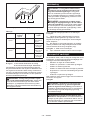
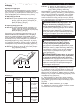
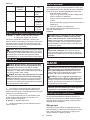
Adjusting the miter angle
CAUTION: After changing the miter angle,
always secure the turn base by tightening the grip
rmly.
NOTICE: When turning the turn base, be sure to
raise the handle fully.
►Fig.16: 1. Lock lever 2. Grip 3. Releasing lever
4. Pointer
Rotate the grip counterclockwise to unlock the turn
base. Turn the grip while holding down the lock lever to
move the turn base. Align the pointer with your desired
angle on the scale then tighten the grip.
NOTE: If you depress the releasing lever, you can
move the turn base without holding down the lock
lever. Tighten the grip at your desired position.
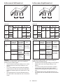
This miter saw employs positive stop function. You can
set 0°, 15°, 22.5°, 31.6°, 45°, and 60° right/left miter
angle quickly. To use this function, move the turn base
close to your desired positive stop angle while holding
down the lock lever. Then release the lock lever and
move the turn base forward until the turn base is locked.
Adjusting the bevel angle
NOTICE: Always remove the upper guide fences
and vertical vise before adjusting the bevel angle.
NOTICE: When changing bevel angles, be sure
to position the kerf boards appropriately as
explained in the "Kerf boards" section.
NOTICE: When tilting the saw blade, be sure to
raise the handle fully.
1. Turn the knob on the slide pole counterclockwise.
►Fig.17: 1. Knob
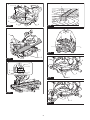
2. Pull and turn the latch lever to the position as
illustrated.
►Fig.18: 1. Latch lever
3. Match the pointer with your desired angle on the
scale by moving the carriage then tighten the knob.
►Fig.19: 1. Bevel angle scale 2. Pointer
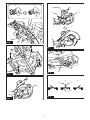
To tilt the carriage to the right, tilt the carriage to the left
slightly and then tilt it to the right while pressing down
the releasing button.
►Fig.20: 1. Releasing button
If you perform a bevel cut greater than 45°, move the
carriage while sliding the releasing lever toward the
front of the tool. You can perform up to 48° bevel cut.
►Fig.21: 1. Releasing lever
This miter saw employs positive stop function. You can
set 22.5° and 33.9° angle to both right and left quickly.
Set the latch lever in the position as illustrated and tilt
the carriage. To change the angle, pull the latch lever
and tilt the carriage.
►Fig.22: 1. Latch lever
CAUTION: After changing the bevel angle,
always secure the knob.
Slide lock
To lock the sliding movement of the carriage, push the
carriage toward the guide fence until it stops. Pull the
stopper pin and rotate it 90°.
►Fig.23: 1. Unlocked position 2. Locked position
3. Stopper pin
Switch action
WARNING: Before plugging in the tool,
always check to see that the switch trigger actu-
ates properly and returns to the "OFF" position
when released. Do not pull the switch trigger hard
without pressing in the lock-off button. This can
cause switch breakage. Operating a tool with a
switch that does not actuate properly can lead to loss
ofcontrolandseriouspersonalinjury.
WARNING: NEVER use tool without a fully
operative switch trigger. Any tool with an inoper-
ative switch is HIGHLY DANGEROUS and must be
repaired before further usage or serious personal
injurymayoccur.
WARNING: NEVER defeat the lock-off button
by taping down or some other means. A switch with
a negated lock-off button may result in unintentional
operationandseriouspersonalinjury.
WARNING: NEVER use the tool if it runs when
you simply pull the switch trigger without press-
ing the lock-off button. A switch in need of repair
may result in unintentional operation and serious
personalinjury.ReturntooltoaMakitaservicecenter
for proper repairs BEFORE further usage.
►Fig.24: 1. Switch trigger 2. Lock-off button 3. Hole
for padlock
To prevent the switch trigger from being accidentally
pulled, a lock-off button is provided. To start the tool,
press in the lock-off button and pull the switch trigger.
Release the switch trigger to stop.
A hole is provided in the switch trigger for insertion of a
padlock to lock the tool off.
WARNING: Do not use a lock with a shank or
cable any smaller than 6.35 mm (1/4") in diameter.
A smaller shank or cable may not properly lock the
tool in the off position and unintentional operation
mayoccurresultinginseriouspersonalinjury.
Electronic function
Constant speed control
The tool is provided with an electronic speed control
which helps maintain a constant blade rotation speed
even under load. A constant blade rotation speed will
result in a very smooth cut.
Soft start feature
This function allows the smooth start-up of the tool by
limiting the start-up torque.

20 ENGLISH
Laser beam action
For model LS1019L only
CAUTION: Never look into the laser beam.
Directlaserbeammayinjureyoureyes.
To turn on the laser beam, press the upper position (I)
of the switch. To turn off the laser beam, press the lower
position (0) of the switch
►Fig.25: 1. Switch for laser
Laser line can be shifted to either the left or right side of
thesawbladebyturningtheadjustingscrewasfollows.
►Fig.26: 1.Adjustingscrew
1. Loosentheadjustingscrewbyturningit
counterclockwise.
2. Withtheadjustingscrewloosened,slidethe
adjustingscrewtotherightorleftasfarasitgoes.
3. Tightentheadjustingscrewrmlyattheposition
where it stops sliding.
NOTE:Laserlineisfactoryadjustedsothatitisposi-
tioned within 1 mm from the side surface of the blade
(cutting position).
NOTE: When laser line appears dim and hard to see
because of direct sunlight, relocate the work area to a
place where there is less direct sunlight.
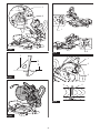
Aligning the laser line
Align the cutting line on your workpiece with the laser
line.
►Fig.27
A) When you want to obtain the correct size on the left
side of workpiece, shift the laser line to the left of the
blade.
B) When you want to obtain the correct size on the right
side of workpiece, shift the laser line to the right of the
blade.
NOTE: Use wood facing against the guide fence
when aligning the cutting line with the laser line at the
side of guide fence in compound cutting (bevel angle
45° and miter angle right 45°).
ASSEMBLY
WARNING: Always be sure that the tool is
switched off and unplugged before working on
the tool. Failure to switch off and unplug the tool may
resultinseriouspersonalinjury.
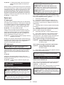
Hex wrench storage
When not in use, store the hex wrench as shown in the
guretokeepitfrombeinglost.
►Fig.28: 1. Hex wrench
Removing and installing saw blade
WARNING: Always be sure that the tool is
switched off and unplugged before installing or
removing the blade. Accidental start up of the tool
mayresultinseriouspersonalinjury.
WARNING: Use only the Makita wrench pro-
vided to install or remove the blade. Failure to use
thewrenchmayresultinovertighteningorinsufcient
tightening of the hex socket bolt and serious personal
injury.
Always lock the carriage with raised position when
removing and installing the blade. Pull the stopper pin
and rotate it 90° with the carriage raised.
►Fig.29: 1. Unlocked position 2. Locked position
3. Stopper pin
Removing the blade
Loosen the hex bolt holding the center cover using the
hex wrench. Raise the blade guard and center cover.
►Fig.30: 1. Center cover 2. Hex wrench 3. Blade
guard
Press the shaft lock to lock the spindle and use the hex
wrench to loosen the hex socket bolt. Then remove the
hexsocketbolt,outerangeandblade.
►Fig.31: 1. Shaft lock 2. Hex wrench 3. Hex socket
bolt (left-handed) 4. Loosen 5. Tighten
Installing the blade
Mount the blade carefully onto the spindle, making
sure that the direction of the arrow on the surface of the
blade matches the direction of the arrow on the blade
case.
►Fig.32: 1. Arrow on the blade case 2. Arrow on the
blade
Installtheouterangeandhexsocketbolt.Tightenthe
hex socket bolt counterclockwise using the hex wrench
while pressing the shaft lock.
►Fig.33: 1. Hex socket bolt 2.Outerange3. Saw
blade 4.Innerange5. Spindle 6. Ring
NOTICE:Iftheinnerangeisremoved,besureto
install it on the spindle with its protrusion facing away
fromtheblade.Iftheangeisinstalledincorrectly,the
angewillrubagainstthemachine.
Return the blade guard and center cover to its original
position. Then tighten the hex bolt clockwise to secure
the center cover. Unlock the stopper pin to release
carriage from the raised position. Lower the handle to
make sure that the blade guard moves properly. Make
sure shaft lock has released spindle before making cut.
WARNING: Before mounting the blade onto
the spindle, always be sure that the correct ring
for the blade's arbor hole you intend to use is
installed between the inner and the outer anges.
Use of the incorrect arbor hole ring may result in the
improper mounting of the blade causing blade move-
ment and severe vibration resulting in possible loss
of control during operation and in serious personal
injury.
Sayfa yükleniyor...
Sayfa yükleniyor...
Sayfa yükleniyor...
Sayfa yükleniyor...
Sayfa yükleniyor...
Sayfa yükleniyor...
Sayfa yükleniyor...
Sayfa yükleniyor...
Sayfa yükleniyor...
Sayfa yükleniyor...
Sayfa yükleniyor...
Sayfa yükleniyor...
Sayfa yükleniyor...
Sayfa yükleniyor...
Sayfa yükleniyor...
Sayfa yükleniyor...
Sayfa yükleniyor...
Sayfa yükleniyor...
Sayfa yükleniyor...
Sayfa yükleniyor...
Sayfa yükleniyor...
Sayfa yükleniyor...
Sayfa yükleniyor...
Sayfa yükleniyor...
Sayfa yükleniyor...
Sayfa yükleniyor...
Sayfa yükleniyor...
Sayfa yükleniyor...
Sayfa yükleniyor...
Sayfa yükleniyor...
Sayfa yükleniyor...
Sayfa yükleniyor...
Sayfa yükleniyor...
Sayfa yükleniyor...
Sayfa yükleniyor...
Sayfa yükleniyor...
Sayfa yükleniyor...
Sayfa yükleniyor...
Sayfa yükleniyor...
Sayfa yükleniyor...
Sayfa yükleniyor...
Sayfa yükleniyor...
Sayfa yükleniyor...
Sayfa yükleniyor...
Sayfa yükleniyor...
Sayfa yükleniyor...
Sayfa yükleniyor...
Sayfa yükleniyor...
Sayfa yükleniyor...
Sayfa yükleniyor...
Sayfa yükleniyor...
Sayfa yükleniyor...
Sayfa yükleniyor...
Sayfa yükleniyor...
Sayfa yükleniyor...
Sayfa yükleniyor...
Sayfa yükleniyor...
Sayfa yükleniyor...
Sayfa yükleniyor...
Sayfa yükleniyor...
Sayfa yükleniyor...
Sayfa yükleniyor...
Sayfa yükleniyor...
Sayfa yükleniyor...
Sayfa yükleniyor...
Sayfa yükleniyor...
Sayfa yükleniyor...
Sayfa yükleniyor...
Sayfa yükleniyor...
Sayfa yükleniyor...
Sayfa yükleniyor...
Sayfa yükleniyor...
Sayfa yükleniyor...
Sayfa yükleniyor...
Sayfa yükleniyor...
Sayfa yükleniyor...
Sayfa yükleniyor...
Sayfa yükleniyor...
Sayfa yükleniyor...
Sayfa yükleniyor...
Sayfa yükleniyor...
Sayfa yükleniyor...
Sayfa yükleniyor...
Sayfa yükleniyor...
Sayfa yükleniyor...
Sayfa yükleniyor...
Sayfa yükleniyor...
Sayfa yükleniyor...
Sayfa yükleniyor...
Sayfa yükleniyor...
Sayfa yükleniyor...
Sayfa yükleniyor...
Sayfa yükleniyor...
Sayfa yükleniyor...
Sayfa yükleniyor...
Sayfa yükleniyor...
Sayfa yükleniyor...
Sayfa yükleniyor...
Sayfa yükleniyor...
Sayfa yükleniyor...
Sayfa yükleniyor...
Sayfa yükleniyor...
Sayfa yükleniyor...
Sayfa yükleniyor...
Sayfa yükleniyor...
Sayfa yükleniyor...
Sayfa yükleniyor...
Sayfa yükleniyor...
Sayfa yükleniyor...
Sayfa yükleniyor...
Sayfa yükleniyor...
Sayfa yükleniyor...
Sayfa yükleniyor...
Sayfa yükleniyor...
Sayfa yükleniyor...
Sayfa yükleniyor...
Sayfa yükleniyor...
Sayfa yükleniyor...
Sayfa yükleniyor...
Sayfa yükleniyor...
Sayfa yükleniyor...
Sayfa yükleniyor...
Sayfa yükleniyor...
Sayfa yükleniyor...
Sayfa yükleniyor...
Sayfa yükleniyor...
Sayfa yükleniyor...
Sayfa yükleniyor...
Sayfa yükleniyor...
Sayfa yükleniyor...
Sayfa yükleniyor...
Sayfa yükleniyor...
Sayfa yükleniyor...
Sayfa yükleniyor...
Sayfa yükleniyor...
Sayfa yükleniyor...
Sayfa yükleniyor...
Sayfa yükleniyor...
Sayfa yükleniyor...
Sayfa yükleniyor...
Sayfa yükleniyor...
Sayfa yükleniyor...
Sayfa yükleniyor...
Sayfa yükleniyor...
Sayfa yükleniyor...
Sayfa yükleniyor...
Sayfa yükleniyor...
Sayfa yükleniyor...
Sayfa yükleniyor...
Sayfa yükleniyor...
Sayfa yükleniyor...
Sayfa yükleniyor...
Sayfa yükleniyor...
Sayfa yükleniyor...
Sayfa yükleniyor...
Sayfa yükleniyor...
-
 1
1
-
 2
2
-
 3
3
-
 4
4
-
 5
5
-
 6
6
-
 7
7
-
 8
8
-
 9
9
-
 10
10
-
 11
11
-
 12
12
-
 13
13
-
 14
14
-
 15
15
-
 16
16
-
 17
17
-
 18
18
-
 19
19
-
 20
20
-
 21
21
-
 22
22
-
 23
23
-
 24
24
-
 25
25
-
 26
26
-
 27
27
-
 28
28
-
 29
29
-
 30
30
-
 31
31
-
 32
32
-
 33
33
-
 34
34
-
 35
35
-
 36
36
-
 37
37
-
 38
38
-
 39
39
-
 40
40
-
 41
41
-
 42
42
-
 43
43
-
 44
44
-
 45
45
-
 46
46
-
 47
47
-
 48
48
-
 49
49
-
 50
50
-
 51
51
-
 52
52
-
 53
53
-
 54
54
-
 55
55
-
 56
56
-
 57
57
-
 58
58
-
 59
59
-
 60
60
-
 61
61
-
 62
62
-
 63
63
-
 64
64
-
 65
65
-
 66
66
-
 67
67
-
 68
68
-
 69
69
-
 70
70
-
 71
71
-
 72
72
-
 73
73
-
 74
74
-
 75
75
-
 76
76
-
 77
77
-
 78
78
-
 79
79
-
 80
80
-
 81
81
-
 82
82
-
 83
83
-
 84
84
-
 85
85
-
 86
86
-
 87
87
-
 88
88
-
 89
89
-
 90
90
-
 91
91
-
 92
92
-
 93
93
-
 94
94
-
 95
95
-
 96
96
-
 97
97
-
 98
98
-
 99
99
-
 100
100
-
 101
101
-
 102
102
-
 103
103
-
 104
104
-
 105
105
-
 106
106
-
 107
107
-
 108
108
-
 109
109
-
 110
110
-
 111
111
-
 112
112
-
 113
113
-
 114
114
-
 115
115
-
 116
116
-
 117
117
-
 118
118
-
 119
119
-
 120
120
-
 121
121
-
 122
122
-
 123
123
-
 124
124
-
 125
125
-
 126
126
-
 127
127
-
 128
128
-
 129
129
-
 130
130
-
 131
131
-
 132
132
-
 133
133
-
 134
134
-
 135
135
-
 136
136
-
 137
137
-
 138
138
-
 139
139
-
 140
140
-
 141
141
-
 142
142
-
 143
143
-
 144
144
-
 145
145
-
 146
146
-
 147
147
-
 148
148
-
 149
149
-
 150
150
-
 151
151
-
 152
152
-
 153
153
-
 154
154
-
 155
155
-
 156
156
-
 157
157
-
 158
158
-
 159
159
-
 160
160
-
 161
161
-
 162
162
-
 163
163
-
 164
164
-
 165
165
-
 166
166
-
 167
167
-
 168
168
-
 169
169
-
 170
170
-
 171
171
-
 172
172
-
 173
173
-
 174
174
-
 175
175
-
 176
176


Makita LS1019 Slide Compound Miter Saw Kullanım kılavuzu
- Tip
- Kullanım kılavuzu
diğer dillerde
- español: Makita LS1019 Slide Compound Miter Saw Manual de usuario
- français: Makita LS1019 Slide Compound Miter Saw Manuel utilisateur
- italiano: Makita LS1019 Slide Compound Miter Saw Manuale utente
- Deutsch: Makita LS1019 Slide Compound Miter Saw Benutzerhandbuch
- português: Makita LS1019 Slide Compound Miter Saw Manual do usuário
- dansk: Makita LS1019 Slide Compound Miter Saw Brugermanual
- Nederlands: Makita LS1019 Slide Compound Miter Saw Handleiding