Stanley SM18 Kullanım kılavuzu
- Kategori
- Elektrikli aletler
- Tip
- Kullanım kılavuzu

ENGLISH (Original Instructions)
SM18
English
French
Russian
Ukrainian
Turkish
ةيبرعلا
14
27
42
61
77
107

ENGLISH (Original Instructions)
2
0000 00-00
a
l
w
ggg
q
mm
cc
aa
p
c
j
ee
dt
e
f
v
u
b
x
o
n
aaa
m
ddd
r
g
k
s
i
ii
bbb
ccc
1
2

3
ENGLISH (Original Instructions)
ii
ff
ee
3
4

ENGLISH (Original Instructions)
4
i
mm
o
j
7
5
6

5
ENGLISH (Original Instructions)
i
nn
pp
v
s
t
e
oo
oo
rr
uu
x
ll
nn
kk
bb
8
9 10
11

ENGLISH (Original Instructions)
6
tt
i
tt
oo
s
v
cc
p
xx
q
yy
ww
cc
12
13 14
15 16

7
ENGLISH (Original Instructions)
v
k
zz
aa
ww
>30mm
ggg
q
yy
xx
17
19
18
20
21 22
ss
hhh

ENGLISH (Original Instructions)
8
dd
bb
c
v
y
I
23
25
26
24

9
ENGLISH (Original Instructions)
ee
ii
ii
h
h
p
fff
27
28

ENGLISH (Original Instructions)
10
qq
gg
qq
qq
29

11
ENGLISH (Original Instructions)
30

ENGLISH (Original Instructions)
12
31
32
34
35
33

13
ENGLISH (Original Instructions)
36
37

ENGLISH (Original Instructions)
14
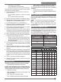
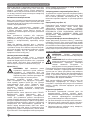
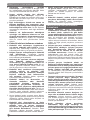
INTENDED USE
Your STANLEY Mitre Saw SM18 has been designed for
cutting wood and aluminum, wood products, aluminum
products and plastics. It performs the sawing operations of
cross-cutting, bevelling and mitring easily, accurately and
safely. This tool is intended for professional use.
SAFETY INSTRUCTIONS
The definitions below describe the level of severity for each
signal word. Please read the manual and pay attention to
these symbols.
DANGER: Indicates an imminently hazardous
situation which, if not avoided, will result in
death or serious injury.
WARNING: Indicates a potentially hazardous
situation which, if not avoided, could result in
death or serious injury.
CAUTION: Indicates a potentially hazardous
situation which, if not avoided, may result in
minor or moderate injury.
NOTICE: Indicates a practice not related to personal injury
which, if not avoided, may result in property damage.
Denotes risk of electric shock.
Denotes risk of fire.
Warning: To reduce the risk of injury, read the
instruction manual.
General Power Tool Safety Warnings
WARNING! Read all safety warnings, instruc-
tions, illustrations and specifications pro-
vided with this power tool. Failure to follow all
instructions listed below may result in electric
shock, fire and/or serious injury.
Save all warnings and instructions for future
reference
The term “power tool” in the warnings refers to your
mains-operated (corded) power tool or battery operated
(cordless) power tool.
1. Work area safety
a. Keep work area clean and well lit. Cluttered or dark
areas invite accidents.
b. Do not operate power tools in explosive
atmospheres, such as in the presence of
flammable liquids, gases or dust. Power tools
create sparks which may ignite the dust or fumes.
c. Keep children and bystanders away while
operating a power tool. Distractions can cause you
to lose control.
2. Electrical Safety
a. Power tool plugs must match the outlet. Never
modify the plug in any way. Do not use any adapter
plugs with earthed (grounded) power tools.
Unmodified plugs and matching outlets will reduce risk
of electric shock.
b. Avoid body contact with earthed or grounded
surfaces such as pipes, radiators, ranges and
refrigerators. There is an increased risk of electric
shock if your body is earthed or grounded.
c. Do not expose power tools to rain or wet
conditions. Water entering a power tool will increase
the risk of electric shock.
d. Do not abuse the cord. Never use the cord for
carrying, pulling or unplugging the power tool.
Keep cord away from heat, oil, sharp edges or
moving parts. Damaged or entangled cords increase
the risk of electric shock.
e. When operating a power tool outdoors, use an
extension cord suitable for outdoor use. Use of
a cord suitable for outdoor use reduces the risk of
electric shock.
f. If operating a power tool in a damp location is
unavoidable, use a residual current device (RCD)
protected supply. Use of an RCD reduces the risk of
electric shock.
3. Personal Safety
a. Stay alert, watch what you are doing and use
common sense when operating a power tool. Do
not use a power tool while you are tired or under
the influence of drugs, alcohol or medication. A
moment of inattention while operating power tools may
result in serious personal injury.
b. Use personal protective equipment. Always wear
eye protection. Protective equipment such as a dust
mask, non-skid safety shoes, hard hat, or hearing
protection used for appropriate conditions will reduce
personal injuries.
c. Prevent unintentional starting. Ensure the switch
is in the off position before connecting to power
source and/or battery pack, picking up or carrying
the tool. Carrying power tools with your finger on the
switch or energising power tools that have the switch
on invites accidents.
d. Remove any adjusting key or wrench before
turning the power tool on. A wrench or a key left
attached to a rotating part of the power tool may result
in personal injury.
e. Do not overreach. Keep proper footing and
balance at all times. This enables better control of
the power tool in unexpected situations.
f. Dress properly. Do not wear loose clothing or
jewellery. Keep your hair and clothing away from
moving parts. Loose clothes, jewellery or long hair
can be caught in moving parts.
g. If devices are provided for the connection of dust
extraction and collection facilities, ensure these
are connected and properly used. Use of dust
collection can reduce dust-related hazards.
h. Do not let familiarity gained from frequent use of
tools allow you to become complacent and ignore
tool safety principles. A careless action can cause
severe injury within a fraction of a second.

15
ENGLISH (Original Instructions)
4. Power Tool Use And Care
a. Do not force the power tool. Use the correct power
tool for your application. The correct power tool will
do the job better and safer at the rate for which it was
designed.
b. Do not use the power tool if the switch does not
turn it on and off. Any power tool that cannot be
controlled with the switch is dangerous and must be
repaired.
c. Disconnect the plug from the power source and/
or remove the battery pack, if detachable from
the power tool before making any adjustments,
changing accessories, or storing power tools.
Such preventive safety measures reduce the risk of
starting the power tool accidentally.
d. Store idle power tools out of the reach of children
and do not allow persons unfamiliar with the
power tool or these instructions to operate the
power tool. Power tools are dangerous in the hands
of untrained users.
e. Maintain power tools and accessories. Check
for misalignment or binding of moving parts,
breakage of parts and any other condition that
may affect the power tool’s operation. If damaged,
have the power tool repaired before use. Many
accidents are caused by poorly maintained power
tools.
f. Keep cutting tools sharp and clean. Properly
maintained cutting tools with sharp cutting edges are
less likely to bind and are easier to control.
g. Use the power tool, accessories and tool bits etc.
in accordance with these instructions, taking into
account the working conditions and the work to
be performed. Use of the power tool for operations
different from those intended could result in a
hazardous situation.
h. Keep handles and grasping surfaces dry, clean
and free from oil and grease. Slippery handles and
grasping surfaces do not allow for safe handling and
control of the tool in unexpected situations.
5. Service
a. Have your power tool serviced by a qualified
repair person using only identical replacement
parts. This will ensure that the safety of the power tool
is maintained.
SAFETY INSTRUCTIONS FOR MITRE SAWS
♦ Mitre saws are intended to cut wood or wood-like
products, they cannot be used with abrasive cut-
off wheels for cutting ferrous material such as
bars, rods, studs, etc. Abrasive dust causes moving
parts such as the lower guard to jam. Sparks from
abrasive cutting will burn the lower guard, the kerf
insert and other plastic parts.
♦ Use clamps to support the workpiece
wheneverpossible. If supporting the workpiece
by hand, you must always keep your hand at least
100 mm from either side of the saw blade. Do not
use this saw to cut pieces that are too small to be
securely clamped or held by hand. If your hand is
placed too close to the saw blade,there is an increased
risk of injury from blade contact.
♦ The workpiece must be stationary and clamped or
held against both the fence and the table. Do not
feed the workpiece into the blade or cut “freehand”
in any way. Unrestrained or moving workpieces could
be thrown at high speeds,causing injury.
♦ Push the saw through the workpiece. Do not
pull the saw through the workpiece. To make a
cut, raise the saw head and pull it out over the
workpiece without cutting, start the motor, press
the saw head down and push the saw through
the workpiece. Cutting on the pull stroke is likely to
cause the saw blade to climb on top of the workpiece
and violently throw the blade assembly towards the
operator.
♦ Never cross your hand over the intended line of
cutting either in front or behind the saw blade.
Supporting the workpiece “cross handed” i.e. holding
the workpiece to the right of the saw blade with your
left hand or vice versa is very dangerous.
♦ Do not reach behind the fence with either hand
closer than 100 mm from either side of the saw
blade, to remove wood scraps, or for any other
reason while the blade is spinning. The proximity
of the spinning saw blade to your hand may not be
obvious and you may be seriously injured.
♦ Inspect your workpiece before cutting. If the
workpiece is bowed or warped, clamp it with the
outside bowed face toward the fence. Always
make certain that there is no gap between the
workpiece, fence and table along the line of the
cut. Bent or warped workpieces can twist or shift and
may cause binding on the spinning saw blade while
cutting. There should be no nails or foreign objects in
the workpiece.
♦ Do not use the saw until the table is clear of all
tools, wood scraps, etc., except for the workpiece.
Small debris or loose pieces of wood or other objects
that contact the revolving blade can be thrown with
high speed.
♦ Cut only one workpiece at a time. Stacked multiple
workpieces cannot be adequately clamped or braced
and may bind on the blade or shift during cutting.
♦ Ensure the mitre saw is mounted or placed on
a level, firm work surface before use.A level and
firm work surface reduces the risk of the mitre saw
becoming unstable.
♦ Plan your work. Every time you change the bevel
or mitre angle setting, make sure the adjustable
fence is set correctly to support the workpiece
and will not interfere with the blade or the
guarding system. Without turning the tool “ON” and
with no workpiece on the table, move the saw blade
through a complete simulated cut to assure there will
be no interference or danger of cutting the fence.
♦ Provide adequate support such as table
extensions, saw horses, etc. for a workpiece that
is wider or longer than the table top. Workpieces
longer or wider than the mitre saw table can tip if not
securely supported. If the cut-off piece or workpiece

ENGLISH (Original Instructions)
16
tips, it can lift the lower guard or be thrown by the
spinning blade.
♦ Do not use another person as a substitute for a
table extension or as additional support. Unstable
support for the workpiece can cause the blade to bind
or the workpiece to shift during the cutting operation
pulling you and the helper into the spinning blade.
♦ Thecut-offpiecemustnotbejammedorpressed
byanymeansagainstthe spinning saw blade. If
confined, i.e. using length stops, the cut-off piece could
get wedged against the blade and thrown violentiy.
♦ Always use aclamp or a fixture designed to
properly support round material such as rods or
tubing. Rods have a tendency to roll while being cut,
causing the blade to “bite” and pull the work with your
hand into the blade.
♦ Let the blade reach full speed before contacting
the workpiece. This will reduce the risk of the
workpiece being thrown.
♦ If the workpiece or blade becomes jammed, turn
the mitre saw off.Wait for all moving parts to stop
and disconnect the plug from the power source
and/ or remove the battery pack. Then work to
free the jammed material. Continued sawing with
a jammed workpiece could cause loss of control or
damage to the mitre saw.
♦ After finishing the cut, release the switch, hold
the saw head down and wait for the blade to stop
before removing the cut-off piece. Reaching with
your hand near the coasting blade is dangerous.
♦ Hold the handle firmly when making an incomplete
cut or when releasing the switch before the saw
head is completely in the down position. The
braking action of the saw may cause the saw head to
be suddenly pulled downward, causing a risk of injury.
ADDITIONAL SAFETY RULES FOR MITRE
SAWS
♦ The machine is provided with a special configured
power supply cord which can only be replaced by the
manufacturer or its authorised service agent.
♦ Do not use the saw to cut other materials than those
recommended by the manufacturer.
♦ Cutting plastics, sap coated wood, and other materials
may cause melted material to accumulate on the blade
tips and the body of the saw blade, increasing the risk
of blade overheating and binding while cutting.
♦ Do not operate the machine without guards in posi-
tion, or if guards do not function or are not maintained
properly.
♦ Ensure that the arm is securely fixed when performing
bevel cuts.
♦ Keep the floor area around the machine level,
well-maintained and free of loose materials, e.g., chips
and cut-offs.
♦ Use correctly sharpened saw blades. Observe the
maximum speed mark on the saw blade.
♦ Make sure all locking knobs and clamp handles are
tight before starting any operation.
♦ Never place either hand in the blade area when the
saw is connected to the electrical power source.
♦ Never attempt to stop a machine in motion rapidly by
jamming a tool or other means against the blade; seri-
ous accidents can occur.
♦ Before using any accessory consult the instruction
manual. The improper use of an accessory can cause
damage.
♦ Use a holder or wear gloves when handling a saw
blade.
♦ Ensure that the saw blade is mounted correctly before
use.
♦ Make sure that the blade rotates in the correct
direction.
♦ Take care when slotting.
♦ Do not use blades of larger or smaller diameter than
recommended. For the proper blade rating refer to the
technical data. Use only the blades specified in this
manual, complying with EN 847-1.
♦ Consider applying specially designed noise-reduction
blades.
♦ Do not use HSS blades.
♦ Do not use cracked or damaged saw blades.
♦ Do not use any abrasive or diamond discs.
♦ Never use your saw without the kerf plate.
♦ Raise the blade from the kerf in the workpiece prior to
releasing the switch.
♦ Do not wedge anything against the fan to hold the
motor shaft.
♦ The blade guard on your saw will automatically raise
when the arm is brought down; it will lower over the
blade when head lock up release lever (cc) is pushed.
♦ Never raise the blade guard manually unless the saw
is switched off. The guard can be raised by hand when
installing or removing saw blades or for inspection of
the saw.
♦ Check periodically that the motor air slots are clean
and free of chips.
♦ Replace the kerf plate when worn. Refer to service
parts list included.
♦ Disconnect the machine from the mains before
carrying out any maintenance work or when changing
the blade.
♦ Never perform any cleaning or maintenance work
when the machine is still running and the head is not
in the rest position.
♦ When possible, always mount the machine to a bench.
♦ The front section of the guard is louvered for visibility
while cutting. Although the louvers dramatically
reduce flying debris, they are openings in the guard
and safety glasses should be worn at all times when
viewing through the louvers.
♦ Connect the saw to a dust collection device when
sawing wood. Always consider factors which influence
exposure of dust such as:
– type of material to be machined (chip board
produces more dust than wood);

17
ENGLISH (Original Instructions)
– sharpness of the saw blade;
– correct adjustment of the saw blade,
– dust extractor with air velocity not less than 20 m/s.
Ensure that the local extraction as well as hoods, baffles
and chutes are properly adjusted.
♦ Please be aware of the following factors influencing
exposure to noise:
– use saw blades designed to reduce the emitted
noise;
– use only well sharpened saw blades;
♦ Machine maintenance shall be conducted periodically;
♦ Machine faults, including guards or saw blade, shall be
reported as soon as they are discovered;
♦ Provide adequate general or localized lighting;
♦ Ensure the operator is adequately trained in the use,
adjustment and operation of the machine;
♦ Ensure that any spacers and spindle rings are suitable
for the purpose as stated in this manual.
♦ Refrain from removing any cut-offs or other parts of
the workpiece from the cutting area while the machine
is running and the saw head is not in the rest position
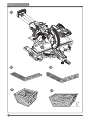
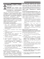
♦ Never cut workpieces shorter than 30 mm(Figure 34).
♦ Without additional support the machine is designed to
accept the maximum workpiece size of:
– Height 75 mm by width 140 mm by length 460 mm
– Longer workpieces need to be supported by suit-
able additional table(work support). Always clamp
the workpiece safely.
♦ In case of an accident or machine failure, immediately
turn the machine off and disconnect machine from the
power source.
♦ Report the failure and mark the machine in suitable
form to prevent other people from using the defective
machine.
♦ When the saw blade is blocked due to abnormal feed
force during cutting, turn the machine off and discon-
nect it from power supply. Remove the workpiece and
ensure that the saw blade runs free. Turn the machine
on and start new cutting operation with reduced feed
force.
♦ Never cut light alloy, especially magnesium.
♦ Whenever the situation allows, mount the machine to
a bench using bolts.
RESIDUAL RISKS
The following risks are inherent to the use of saws:
– injuries caused by touching the rotating parts
In spite of the application of the relevant safety reg-
ulations and the implementation of safety devices,
certain residual risks cannot be avoided. These are:
– Impairment of hearing.
– Risk of accidents caused by the uncovered parts of the
rotating saw blade.
– Risk of injury when changing the blade.
– Risk of squeezing fingers when opening the guards.
– Health hazards caused by breathing dust developed
when sawing wood, especially oak, beech and MDF.
The following factors increase the risk of breathing
problems:
– No dust extractor connected when sawing wood.
– Insufficient dust extraction caused by uncleaned exhaust
filters.
ELECTRICAL SAFETY
Only one voltage is applicable to this tool. Be sure to check
that the power supply corresponds to the voltage on the
rating plate.
Your Stanley tool is equipped with double insula-
tion, hence, it does not require to be earthed
When the power cord is damaged, have it sent
to a STANLEY service center for replacement to specially
prepared cables.
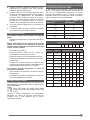
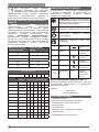
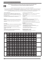
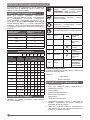
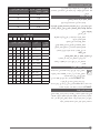
USING AN EXTENSION CABLE
If an extension cable is required, use an approved 3–core
extension cable suitable for the power input of this tool
(see Technical Data).The minimum conductor size is 1.5
mm
2
; the maximum length is 30 m. When using a cable
reel, always unwind the cable completely.
Cable cross-sectional
area (mm
2
)
Cable rated current
(Ampere)
0.75 6
1.00 10
1.50 15
2.50 20
4.00 25
Cable length (m)
7.5 15 25 30 45 60
Voltage Amperes Cable rated current (Ampere)
110~127 0 - 2.0 6 6 6 6 6 10
2.1 - 3.4 6 6 6 6 15 15
3.5 - 5.0 6 6 10 15 20 20
5.1 - 7.0 10 10 15 20 20 25
7.1 - 12.0 15 15 20 25 25 -
12.1 - 20.0 20 20 25 - - -
230 0 - 2.0 6 6 6 6 6 6
2.1 - 3.4 6 6 6 6 6 6
3.5 - 5.0 6 6 6 6 10 15
5.1 - 7.0 10 10 10 10 15 15
7.1 - 12.0 15 15 15 15 20 20
12.1 - 20.0 20 20 20 20 25 -

ENGLISH (Original Instructions)
18
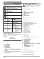
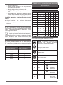
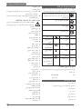
LABELS ON TOOL
In addition to the pictographs used in this manual, the
labels on the tool show the following pictographs:
WARNING! To reduce the risk of injury, the user
must read the instruction manual before use.
Wear a dust mask.
Wear ear protection.
Wear safety glasses or goggles.
Keep your hands away from this area
V Volts
Direct Current
A Amperes n
0
No-Load Speed
Hz Hertz
Class II Construction
WWatts
Earthing Terminal
min minutes
Safety Alert Symbol
Alternating
Current
/min.
Revolutions or
Reciprocation per
minute
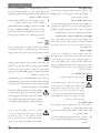
Date Code Position (Fig. 1)
The Date Code, which also includes the year of
manufacture, is printed into the housing.
Example: 2019 XX XX
Year of Manufacture
THE PACKAGE CONTAINS
1 Mitre Saw
1 Blade wrench stored in wrench pocket
1 Saw blade
1 Dust bag
1 Vertical clamp
1 Rear support
1 Instruction manual
♦ Check for damage to the tool, parts or accessories
which may have occurred during transport.
♦ Take the time to thoroughly read and understand this
manual prior to operation.
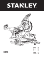
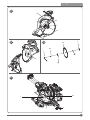
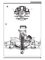
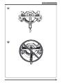
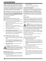
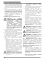
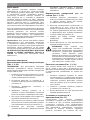
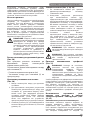
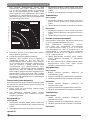
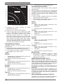
Description (Fig. 1, 2, 3, 5, 6, 12, 23, 27, 28)
WARNING: Never modify the power tool or any
part of it. Damage or personal injury could result.
a. Operating handle
b. Lower guard
c. Right side, fence
d. Table
e. Mitre lock knob
f. Mitre scale
g. Base
h. Extension knob
i. Wrench
j. Bench mounting holes
k. Fence clamping knob
l. Trigger switch
m. Carrying handle
n. Dust spout
o. Lock down pin
p. Bevel clamp knob
q. Bevel scale
r. Hand indentation
s. Kerf plate
t. Mitre detent
u. Date code
v. Left side, fence
w. End cap
x. Spindle lock
y. Hole for padlock
z. Angle position stop
aa. Bevel position adjustment stop
bb. LED switch
cc. Vertical position adjustment stop
dd. Lock-off lever
ee. Length stop
ff. Dust bag
gg. Vertical clamp
ii. Work support
jj. Fence stop screw
mm. Rear support
aaa. Rear handle
bbb. Mitre arm support
ccc. Work support clamping knob
ddd. Rail lock knob
fff. Bevel lock knob
ggg. Slide stop control
ASSEMBLY AND ADJUSTMENT
WARNING: To reduce the risk of injury, turn unit
off and disconnect machine from power source
before installing and removing accessories,
before adjusting or changing set-ups or when
making repairs. Be sure the trigger switch is in the OFF
position. An accidental start-up can cause injury.

19
ENGLISH (Original Instructions)
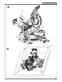
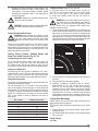
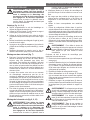
3. Remove the blade locking screw (nn) and the outside
arbor collar (pp).
4. Install the saw blade (oo) onto the blade adaptor (uu)
seated directly against the inside arbor collar (rr), mak-
ing sure that the teeth at the bottom edge of the blade
are pointing toward the back of the saw (away from the
operator).
5. Replace the outer arbor collar (pp).
6. Tighten the blade locking screw (nn) carefully by turn-
ing counter-clockwise while holding the spindle lock
engaged with your other hand.
7. Return the guard bracket (ll) to its original position and
firmly tighten the guard bracket screw (kk) to hold brack-
et in place.
WARNING! Be aware the saw blade shall be
replaced in the described way only. Only use
saw blades as specified under Technical Data.
WARNING! The guard bracket(ll) must be
returned to its original position and the guard
bracket screw(kk) tightened before activating the
saw.
WARNING! Failure to do so may allow the guard
to contact the spinning saw blade resulting in
damage to the saw and severe personal injury.
Your mitre saw was accurately adjusted at the factory. If
readjustment due to shipping and handling or any other
reason is required, follow the steps below to adjust your
saw. Once made, these adjustments should remain
accurate.
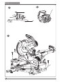
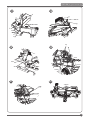
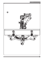
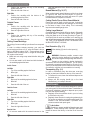
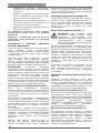
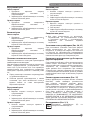
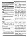
Checking and Adjusting the Mitre Scale
(Fig. 11, 12, 13)
1. Loosen the mitre lock knob (e), depress the mitre detent
(t) to release the mitre arm. Swing the mitre arm until the
latch locates it at the 0° mitre position. Do not lock mitre
lock knob (e).
2. Pull down the head until the blade just enters the saw
kerf (s).
3. Place a square (tt) against the left side fence (v) and
blade (oo) (Fig. 11).
WARNING: Do not touch the tips of the blade
teeth with the square.
If adjustment is required, proceed as follows:
4. Tighten the mitre lock knob (e). Loose the fence clamp-
ing knob (k), remove the left side fence (v) and right side
fence (c).
5. Loose 4 hex bolts behind the fence, adjust the base
fence as the necessary to against the square (tt).
6. Tighten the hex bolts, and install the side fence.the
wrench (i) to tighten the hex bolts on the fence in the
order from the right side.
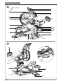
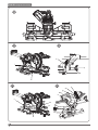
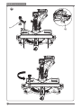
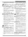
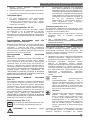
Unpacking (Fig. 2, 4, 5, 6)
♦ Remove the saw from the packing material carefully
using the carrying handle (m) and rear handle(aaa).
♦ Use the supplied blade wrench(i) to mount the rear
support (mm) to the back of base(g).
♦ Press down the operating handle (a) and pull out the
lock down pin (o), as shown.
♦ Gently release the downward pressure and allow the
arm to rise to its full height.
Bench Mounting (Fig. 7)
♦ Holes (j) are provided in all four feet to facilitate bench
mounting. Always mount your saw firmly to prevent
movement. To enhance the portability, the tool can be
mounted to a piece of 15 mm or thinner plywood which
can then be clamped to your work support or moved to
other job sites and reclamped.
♦ When mounting your saw to a piece of ply-
wood, make sure that the mounting screws
do not protrude from the bottom of the wood.
The plywood must sit flush on the work support. When
clamping the saw to any work surface, clamp only on
the clamping bosses where the mounting screw holes
are located. Clamping at any other point will interfere
with the proper operation of the saw.
♦ To prevent binding and inaccuracy, be sure the moun-
ting surface is not warped or otherwise uneven. If the
saw rocks on the surface, place a thin piece of material
under one saw foot until the saw is firm on the moun-
ting surface.
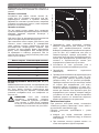
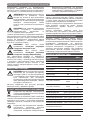
Mounting the Saw Blade (Fig. 8, 9, 10)
WARNING: To reduce the risk of injury, turn unit
off and disconnect machine from power source
before installing and removing accessories,
before adjusting or changing set-ups or when
making repairs. Be sure the trigger switch is in the OFF
position. An accidental start-up can cause injury.
♦ Never depress the spindle lock button while the blade
is under power or coasting.
♦ Do not cut light alloy and ferrous metal (containing iron
or steel) or masonry or fibre cement product with this mitre
saw.
♦ Should use the corresponding blade cutting different
materials.
1. With the lower guard held in the raised position loosen
the guard bracket screw (kk) until the guard bracket (ll)
raises far enough to access the blade locking screw
(nn).
2. Depress the spindle lock button (x) with one hand and
with the other hand use the wrench (i) provided to
loosen the left-hand threaded blade locking screw (nn)
by turning clockwise.
WARNING: To use the spindle lock, press the
button as shown and rotate the spindle by hand
until you feel the lock engage.
Continue to hold the lock button in to keep the spindle from
turning.

ENGLISH (Original Instructions)
20
5. To achieve a 0° or a 45° right/left bevel, the three adjust-
ment stop screws must be adjusted to allow the saw arm
to move as necessary.
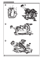
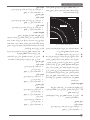
Adjusting the Depth Stop (Sawing Grooves)
(Fig.20)
This operation is necessary if you want to saw a groove.
– Move the depth stop plate (hhh) to the place as shown
Fig 20.
– Tilt the tool head by the handle to the position at which the
requested groove depth is reached.
– Turn the adjusting screw(ss) clockwise until the end of the
screw touches the housing stop.
– Guide the tool arm slowly upward.
Return the depth stop plate (hhh) to its original position
once sawing grooves done.
Ensure that saw blades do not touch any part of the base
or kerf plate.
Guard Actuation and Visibility
The blade guard on your saw has been designed to automat-
ically raise when the arm is brought down and to lower over
the blade when the arm is raised.
The guard can be raised by hand when installing or removing
saw blades or for inspection of the saw. NEVER RAISE
THE BLADE GUARD MANUALLY UNLESS THE SAW IS
TURNED OFF.
NOTE: Certain special cuts will require that you manually
raise the guard. The front section of the guard is louvered
for visibility while cutting. Although the louvers dramatically
reduce flying debris, they are openings in the guard and
safety glasses should be worn at all times when viewing
through the louvers.
Automatic Electric Brake
Your saw is equipped with an automatic electric blade brake
which stops the saw blade within 10 seconds of trigger
release. This is not adjustable.
On occasion, there may be a delay after trigger release to
brake engagement. On rare occasions, the brake may not
engage at all and the blade will coast to a stop.
If a delay or “skipping” occurs, turn the saw on and off 4 or 5
times. If the condition persists, have the tool serviced by an
authorized STANLEY service center.
Always be sure the blade has stopped before removing it from
the kerf. The brake is not a substitute for guards or for ensur-
ing your own safety by giving the saw your complete attention.
Kerf Plate Adjustment
To adjust the kerf plates, loosen the screws holding the
kerf plates in place. Adjust the kerf plates are as close
as possible without interfering with the blade’s movement.
Brushes (Fig. 1)
WARNING: To reduce the risk of serious person-
al injury, turn off the tool and disconnect it from
the power source before attempting to move it,
change accessories or make any adjustments.
Inspect carbon brushes regularly by unplugging the
tool, removing the Brush holder cap (W) that holds the
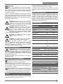
Checking and Adjusting the Blade to the Table
(Fig. 14, 15, 16)
1. Loosen the bevel clamp knob (p).
2. Press the mitre arm to the right to ensure it is fully
vertical with the angle position stop located against the
vertical position adjustment stop (cc) and tighten the
bevel clamp knob.
3. Pull down the head until the blade just enters the saw
kerf (s).
4. Place a set square (tt) on the table and up against
the blade (oo) (Fig. 15).
WARNING: Do not touch the tips of the blade
teeth with the square.
If adjustment is required, proceed as follows:
5. Loosen the lock nut (ww) a few turns and turn the bevel
position adjustment stop screw (cc) in or out until the
pointer (xx) indicates 45°-0° with the angle position stop
resting on the bevel position adjustment stop.
6. Firmly tighten the lock nut (ww) while holding the stop
screw(cc) stationary.
7. If the bevel pointer (xx) does not indicate zero on the
bevel scale (q), loosen the screw (yy) that secures the
pointer and move the pointer as necessary
Adjusting the Fence (Fig. 17)
The upper part of the fence can be adjusted to provide
clearance, allowing the saw to bevel to 45° left and 0° right.
To adjust the left fence (v) and right side fence(c):
1. Loosen the plastic knob (k) and slide the fence to the left.
2. Make a no load running with the saw switched off and
check for clearance. Adjust the fence to be as close to
the blade as practical to provide maximum workpiece
support, without interfering with the up and down move-
ment of the arm.
3. Tighten the knob securely.
WARNING: The guide grooves (zz) can become
clogged with sawdust. Use a stick or some low
pressure air to clear the guide grooves.
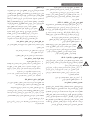
Checking and Adjusting the Bevel Angle
(Fig. 17, 18, 19)
1. Loosen the left side fence clamping knob (k) and slide
the upper part of the left side fence to the left as far as it
will go.
2. Loosen the bevel clamp knob (p) and move the saw arm
to the left 45° bevel position
If adjustment is required, proceed as follows:
3. Loosen the locknut (ww) a few turns and turn the bevel
position adjustment stop screw (aa) in or out until the
pointer (xx) indicates 45° with the angle position stop (z)
resting on the bevel position adjustment stop.
4. Firmly tighten the lock nut (ww) while holding the stop
screw (aa) stationary.
Sayfa yükleniyor ...
Sayfa yükleniyor ...
Sayfa yükleniyor ...
Sayfa yükleniyor ...
Sayfa yükleniyor ...
Sayfa yükleniyor ...
Sayfa yükleniyor ...
Sayfa yükleniyor ...
Sayfa yükleniyor ...
Sayfa yükleniyor ...
Sayfa yükleniyor ...
Sayfa yükleniyor ...
Sayfa yükleniyor ...
Sayfa yükleniyor ...
Sayfa yükleniyor ...
Sayfa yükleniyor ...
Sayfa yükleniyor ...
Sayfa yükleniyor ...
Sayfa yükleniyor ...
Sayfa yükleniyor ...
Sayfa yükleniyor ...
Sayfa yükleniyor ...
Sayfa yükleniyor ...
Sayfa yükleniyor ...
Sayfa yükleniyor ...
Sayfa yükleniyor ...
Sayfa yükleniyor ...
Sayfa yükleniyor ...
Sayfa yükleniyor ...
Sayfa yükleniyor ...
Sayfa yükleniyor ...
Sayfa yükleniyor ...
Sayfa yükleniyor ...
Sayfa yükleniyor ...
Sayfa yükleniyor ...
Sayfa yükleniyor ...
Sayfa yükleniyor ...
Sayfa yükleniyor ...
Sayfa yükleniyor ...
Sayfa yükleniyor ...
Sayfa yükleniyor ...
Sayfa yükleniyor ...
Sayfa yükleniyor ...
Sayfa yükleniyor ...
Sayfa yükleniyor ...
Sayfa yükleniyor ...
Sayfa yükleniyor ...
Sayfa yükleniyor ...
Sayfa yükleniyor ...
Sayfa yükleniyor ...
Sayfa yükleniyor ...
Sayfa yükleniyor ...
Sayfa yükleniyor ...
Sayfa yükleniyor ...
Sayfa yükleniyor ...
Sayfa yükleniyor ...
Sayfa yükleniyor ...
Sayfa yükleniyor ...
Sayfa yükleniyor ...
Sayfa yükleniyor ...
Sayfa yükleniyor ...
Sayfa yükleniyor ...
Sayfa yükleniyor ...
Sayfa yükleniyor ...
Sayfa yükleniyor ...
Sayfa yükleniyor ...
Sayfa yükleniyor ...
Sayfa yükleniyor ...
Sayfa yükleniyor ...
Sayfa yükleniyor ...
Sayfa yükleniyor ...
Sayfa yükleniyor ...
Sayfa yükleniyor ...
Sayfa yükleniyor ...
Sayfa yükleniyor ...
Sayfa yükleniyor ...
Sayfa yükleniyor ...
Sayfa yükleniyor ...
Sayfa yükleniyor ...
Sayfa yükleniyor ...
Sayfa yükleniyor ...
Sayfa yükleniyor ...
Sayfa yükleniyor ...
Sayfa yükleniyor ...
Sayfa yükleniyor ...
Sayfa yükleniyor ...
Sayfa yükleniyor ...
Sayfa yükleniyor ...
-
 1
1
-
 2
2
-
 3
3
-
 4
4
-
 5
5
-
 6
6
-
 7
7
-
 8
8
-
 9
9
-
 10
10
-
 11
11
-
 12
12
-
 13
13
-
 14
14
-
 15
15
-
 16
16
-
 17
17
-
 18
18
-
 19
19
-
 20
20
-
 21
21
-
 22
22
-
 23
23
-
 24
24
-
 25
25
-
 26
26
-
 27
27
-
 28
28
-
 29
29
-
 30
30
-
 31
31
-
 32
32
-
 33
33
-
 34
34
-
 35
35
-
 36
36
-
 37
37
-
 38
38
-
 39
39
-
 40
40
-
 41
41
-
 42
42
-
 43
43
-
 44
44
-
 45
45
-
 46
46
-
 47
47
-
 48
48
-
 49
49
-
 50
50
-
 51
51
-
 52
52
-
 53
53
-
 54
54
-
 55
55
-
 56
56
-
 57
57
-
 58
58
-
 59
59
-
 60
60
-
 61
61
-
 62
62
-
 63
63
-
 64
64
-
 65
65
-
 66
66
-
 67
67
-
 68
68
-
 69
69
-
 70
70
-
 71
71
-
 72
72
-
 73
73
-
 74
74
-
 75
75
-
 76
76
-
 77
77
-
 78
78
-
 79
79
-
 80
80
-
 81
81
-
 82
82
-
 83
83
-
 84
84
-
 85
85
-
 86
86
-
 87
87
-
 88
88
-
 89
89
-
 90
90
-
 91
91
-
 92
92
-
 93
93
-
 94
94
-
 95
95
-
 96
96
-
 97
97
-
 98
98
-
 99
99
-
 100
100
-
 101
101
-
 102
102
-
 103
103
-
 104
104
-
 105
105
-
 106
106
-
 107
107
-
 108
108


Stanley SM18 Kullanım kılavuzu
- Kategori
- Elektrikli aletler
- Tip
- Kullanım kılavuzu
Diğer dillerde
- français: Stanley SM18 Manuel utilisateur
- English: Stanley SM18 User manual
- русский: Stanley SM18 Руководство пользователя
İlgili Makaleler
Diğer Belgeler
-
DeWalt DWS715 Kullanım kılavuzu
-
Makita LS0816F Kullanım kılavuzu
-
Ferm MSM1040 Radial Mitre Saw Kullanım kılavuzu
-
-
Black & Decker CS1250L Kullanım kılavuzu
-
DeWalt DW712 Kullanım kılavuzu
-
Ferm MSM1040 Kullanım kılavuzu
-
-
DeWalt DWS771 Kullanım kılavuzu
-
DeWalt D27113 Kullanım kılavuzu