
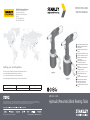
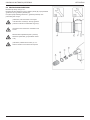
INSTRUCTION AND
SERVICE MANUAL
EZM1000 - 2000
Hydraulic/Pneumatic Blind Riveting Tools
EN
Hydraulic/Pneumatic Blind Riveting Tools
BG
Хидравличен/пневматичен пистолет
за слепи нитове
HR
Hidraulički / pneumatski alati zaslijepe
zakovice
CZ
Hydropneumatické nářadí natrhací nýty
RO
Unelte hidro-pneumatice pentru nituire
HU
Hidraulikus / pneumatikus vakszegecs
belövő szerszám
SK
Hydraulické/pneumatické náradia
naumiestňovanie slepých nitov
SL
Hidravlično/pnevmatsko orodje zaslepe
zakovice
RU
Гидропневматические заклепочники
для потайных заклепок
AR
ﺔﻴﺋاﻮﻬﻟا /ﺔﻴﻜﻴﻟورﺪﻴﻬﻟا ﺔﻴﻔﺨﳌا ﻢﻴﺷاﱪﻟا ﺖﻴﺒﺜﺗ تاودأ
LV
Hidropneimatiskais slēpto kniežu
kniedētājs
LT
Hidrauliniai/ pneumatiniai kniedytuvai
ET
Hüdropneumaatilised needipüstolid
EL
Υδραυλικά/πνευματικά εργαλεία
τοποθέτησης τυφλών πριτσινιών
TR
Hidrolik/Pnömatik Kör Perçin Yerleştirme
Aletleri
STANLEY Engineered Fastening
STANLEY House, Works Road
Letchworth Garden City
Hertfordshire, United Kingdom
SG6 1JY
Tel: +44 1582 900 000
Fax: +44 1582 900 001
Holding your world together®
Find your closest STANLEY Engineered Fastening location on
www.stanleyEngineeredFastening.com/contact
For an authorized distributor nearby please check
www.stanleyEngineeredFastening.com/econtact/distributors
Manual Number Issue C/N
07900-09707 A 21/124
Stanley Engineered Fastening — adivision of Stanley Black and Decker — is the global leader in precision fastening and assembly solutions. Our
industry-leading brands, Avdel®, Integra™, Nelson®, Optia™, POP®, Stanley® Assembly Technologies, and Tucker®, elevate what our customers create.
Backed by ateam of passionate and responsive problem-solvers, we empower engineers who are changing the world.
©2021 Stanley Engineered Fastening. All Rights Reserved. stanleyengineeredfastening.com

1
©2021 STANLEY Black & Decker
All rights reserved.
The information provided may not be reproduced and/or made public in any way and through any means (electronically or
mechanically) without prior explicit and written permission from STANLEY Engineered Fastening. The information provided
is based on the data known at the moment of the introduction of this product. STANLEY Engineered Fastening pursues a
policy of continuous product improvement and therefore the products may be subject to change. The information provided
is applicable to the product as delivered by STANLEY Engineered Fastening. Therefore, STANLEY Engineered Fastening
cannot be held liable for any damage resulting from deviations from the original speci cations of the product.
The information available has been composed with the utmost care. However, STANLEY Engineered Fastening will not
accept any liability with respect to any faults in the information nor for the consequences thereof. STANLEY Engineered
Fastening will not accept any liability for damage resulting from activities carried out by third parties. The working names,
trade names, registered trademarks, etc. used by STANLEY Engineered Fastening should not be considered as being free,
pursuant to the legislation with respect to the protection of trade marks.
CONTENT
1. SAFETY DEFINITIONS . . . . . . . . . . . . . . . . . . . . . . . . . . . . . . . . . . . . . . . . . . . . . . . . . . . . . . . . . . . . . . . . . . . . . . . . . . . . . . . . . . .2
1.1 GENERAL SAFETY RULES . . . . . . . . . . . . . . . . . . . . . . . . . . . . . . . . . . . . . . . . . . . . . . . . . . . . . . . . . . . . . . . . . . . . . . . . . . . . . . . . . . . 2
1.2 PROJECTILE HAZARDS. . . . . . . . . . . . . . . . . . . . . . . . . . . . . . . . . . . . . . . . . . . . . . . . . . . . . . . . . . . . . . . . . . . . . . . . . . . . . . . . . . . . . . 2
1.3 OPERATING HAZARDS . . . . . . . . . . . . . . . . . . . . . . . . . . . . . . . . . . . . . . . . . . . . . . . . . . . . . . . . . . . . . . . . . . . . . . . . . . . . . . . . . . . . . . 3
1.4 REPETITIVE MOTIONS HAZARDS . . . . . . . . . . . . . . . . . . . . . . . . . . . . . . . . . . . . . . . . . . . . . . . . . . . . . . . . . . . . . . . . . . . . . . . . . . . . 3
1.5 ACCESSORY HAZARDS. . . . . . . . . . . . . . . . . . . . . . . . . . . . . . . . . . . . . . . . . . . . . . . . . . . . . . . . . . . . . . . . . . . . . . . . . . . . . . . . . . . . . . 3
1.6 WORKPLACE HAZARDS. . . . . . . . . . . . . . . . . . . . . . . . . . . . . . . . . . . . . . . . . . . . . . . . . . . . . . . . . . . . . . . . . . . . . . . . . . . . . . . . . . . . . 3
1.7 NOISE HAZARDS . . . . . . . . . . . . . . . . . . . . . . . . . . . . . . . . . . . . . . . . . . . . . . . . . . . . . . . . . . . . . . . . . . . . . . . . . . . . . . . . . . . . . . . . . . . 3
1.8 VIBRATION HAZARDS. . . . . . . . . . . . . . . . . . . . . . . . . . . . . . . . . . . . . . . . . . . . . . . . . . . . . . . . . . . . . . . . . . . . . . . . . . . . . . . . . . . . . . . 4
1.9 ADDITIONAL SAFETY INSTRUCTIONS FOR PNEUMATIC POWER TOOLS. . . . . . . . . . . . . . . . . . . . . . . . . . . . . . . . . . . . . . 4
2. SAFETY . . . . . . . . . . . . . . . . . . . . . . . . . . . . . . . . . . . . . . . . . . . . . . . . . . . . . . . . . . . . . . . . . . . . . . . . . . . . . . . . . . . . . . . . . . . . . . . .5
2.1 SAFETY INSTRUCTIONS. . . . . . . . . . . . . . . . . . . . . . . . . . . . . . . . . . . . . . . . . . . . . . . . . . . . . . . . . . . . . . . . . . . . . . . . . . . . . . . . . . . . . 5
2.2 PERSONS . . . . . . . . . . . . . . . . . . . . . . . . . . . . . . . . . . . . . . . . . . . . . . . . . . . . . . . . . . . . . . . . . . . . . . . . . . . . . . . . . . . . . . . . . . . . . . . . . . . 5
2.3 WORK ENVIRONMENT . . . . . . . . . . . . . . . . . . . . . . . . . . . . . . . . . . . . . . . . . . . . . . . . . . . . . . . . . . . . . . . . . . . . . . . . . . . . . . . . . . . . . . 6
2.4 TOOLS. . . . . . . . . . . . . . . . . . . . . . . . . . . . . . . . . . . . . . . . . . . . . . . . . . . . . . . . . . . . . . . . . . . . . . . . . . . . . . . . . . . . . . . . . . . . . . . . . . . . . . 6
2.5 DATE CODE. . . . . . . . . . . . . . . . . . . . . . . . . . . . . . . . . . . . . . . . . . . . . . . . . . . . . . . . . . . . . . . . . . . . . . . . . . . . . . . . . . . . . . . . . . . . . . . . . 6
2.6 TYPE IDENTIFICATION . . . . . . . . . . . . . . . . . . . . . . . . . . . . . . . . . . . . . . . . . . . . . . . . . . . . . . . . . . . . . . . . . . . . . . . . . . . . . . . . . . . . . . 6
3. MAIN COMPONENTS . . . . . . . . . . . . . . . . . . . . . . . . . . . . . . . . . . . . . . . . . . . . . . . . . . . . . . . . . . . . . . . . . . . . . . . . . . . . . . . . . . . .7
3.1 COMPONENTS. . . . . . . . . . . . . . . . . . . . . . . . . . . . . . . . . . . . . . . . . . . . . . . . . . . . . . . . . . . . . . . . . . . . . . . . . . . . . . . . . . . . . . . . . . . . . . 7
3.2 NOSE PIECES . . . . . . . . . . . . . . . . . . . . . . . . . . . . . . . . . . . . . . . . . . . . . . . . . . . . . . . . . . . . . . . . . . . . . . . . . . . . . . . . . . . . . . . . . . . . . . . 7
4. OPERATION . . . . . . . . . . . . . . . . . . . . . . . . . . . . . . . . . . . . . . . . . . . . . . . . . . . . . . . . . . . . . . . . . . . . . . . . . . . . . . . . . . . . . . . . . . . .8
4.1 CONTROLS . . . . . . . . . . . . . . . . . . . . . . . . . . . . . . . . . . . . . . . . . . . . . . . . . . . . . . . . . . . . . . . . . . . . . . . . . . . . . . . . . . . . . . . . . . . . . . . . . 8
4.2 MANDREL COLLECTOR . . . . . . . . . . . . . . . . . . . . . . . . . . . . . . . . . . . . . . . . . . . . . . . . . . . . . . . . . . . . . . . . . . . . . . . . . . . . . . . . . . . . . 9
4.3 REVOLVABLE AIR OUTLET. . . . . . . . . . . . . . . . . . . . . . . . . . . . . . . . . . . . . . . . . . . . . . . . . . . . . . . . . . . . . . . . . . . . . . . . . . . . . . . . . . . 9
4.4 360° REVOLVABLE AIR SUPPLY UNIT. . . . . . . . . . . . . . . . . . . . . . . . . . . . . . . . . . . . . . . . . . . . . . . . . . . . . . . . . . . . . . . . . . . . . . . . . 9
5. USE . . . . . . . . . . . . . . . . . . . . . . . . . . . . . . . . . . . . . . . . . . . . . . . . . . . . . . . . . . . . . . . . . . . . . . . . . . . . . . . . . . . . . . . . . . . . . . . . . 10
6. MAINTENANCE . . . . . . . . . . . . . . . . . . . . . . . . . . . . . . . . . . . . . . . . . . . . . . . . . . . . . . . . . . . . . . . . . . . . . . . . . . . . . . . . . . . . . . . 12
6.1 FRONT SLEEVE . . . . . . . . . . . . . . . . . . . . . . . . . . . . . . . . . . . . . . . . . . . . . . . . . . . . . . . . . . . . . . . . . . . . . . . . . . . . . . . . . . . . . . . . . . . .12
6.2 CLAMPING JAWS . . . . . . . . . . . . . . . . . . . . . . . . . . . . . . . . . . . . . . . . . . . . . . . . . . . . . . . . . . . . . . . . . . . . . . . . . . . . . . . . . . . . . . . . . .13
7. TROUBLE SHOOTING . . . . . . . . . . . . . . . . . . . . . . . . . . . . . . . . . . . . . . . . . . . . . . . . . . . . . . . . . . . . . . . . . . . . . . . . . . . . . . . . . . 14
8. TECHNICAL DATA . . . . . . . . . . . . . . . . . . . . . . . . . . . . . . . . . . . . . . . . . . . . . . . . . . . . . . . . . . . . . . . . . . . . . . . . . . . . . . . . . . . . . 15
9. EC DECLARATION OF CONFORMITY . . . . . . . . . . . . . . . . . . . . . . . . . . . . . . . . . . . . . . . . . . . . . . . . . . . . . . . . . . . . . . . . . . . . 16
10. UK DECLARATION OF CONFORMITY . . . . . . . . . . . . . . . . . . . . . . . . . . . . . . . . . . . . . . . . . . . . . . . . . . . . . . . . . . . . . . . . . . . . 17
ORIGINAL INSTRUCTION ENGLISH

2
This instruction manual must be read by any person installing or operating this tool with particular attention to the
following safety rules.
Always wear impact-resistant eye protection during operation of the tool. The grade of protection required should
be assessed for each use.
Use of the tool can expose the operator’shands to hazards, including crushing, impacts, cuts and abrasions and
heat. Wear suitable gloves to protect hands.
Use hearing protection in accordance with employer’sinstructions and as required by occupational health and
safety regulations.
1. SAFETY DEFINITIONS
The de nitions below describe the level of severity for each signal word. Please read the manual and pay attention to these
symbols.
DANGER: Indicates an imminently hazardous situation which, if not avoided, will result in death or serious injury.
WARNING: Indicates apotentially hazardous situation which, if not avoided, could result in death or serious injury.
CAUTION: Indicates apotentially hazardous situation which, if not avoided, may result in minor or moderate injury.
CAUTION: Used without the safety alert symbol indicates apotentially hazardous situation which, if not avoided, may
result in property damage.
Improper operation or maintenance of this product could result in serious injury and property damage. Read and
understand all warnings and operating instructions before using this equipment. When using power tools, basic safety
precautions must always be followed to reduce the risk of personal injury.
SAVE ALL WARNINGS AND INSTRUCTIONS FOR FUTURE REFERENCE
1.1 GENERAL SAFETY RULES
• For multiple hazards, read and understand the safety instructions before installing, operating, repairing, maintaining,
changing accessories on, or working near the tool. Failure to do so can result in serious bodily injury.
• Only quali ed and trained operators must install, adjust or use the tool.
• DO NOT use outside the design intent of placing STANLEY Engineered Fastening Blind Rivets.
• Use only parts, fasteners, and accessories recommended by the manufacturer.
• DO NOT modify the tool. Modi cations can reduce the e ectiveness of safety measures and increase the risks to the
operator. Any modi cation to the tool undertaken by the customer will be the customer’s entire responsibility and void
any applicable warranties.
• Do not discard the safety instructions; give them to the operator.
• Do not use the tool if it has been damaged.
• Prior to use, check for misalignment or binding of moving parts, breakage of parts, and any other condition that a ects
the tool’s operation. If damaged, have the tool serviced before using. Remove any adjusting key or wrench before use.
• Tools shall be inspected periodically to verify that the ratings and markings required by this part of ISO 11148 are
legibly marked on the tool. The employer/user shall contact the manufacturer to obtain replacement marking labels
when necessary.
• The tool must be maintained in a safe working condition at all times and examined at regular intervals for damage
and function by trained personnel. Any dismantling procedure will be undertaken only by trained personnel. Do not
dismantle this tool without prior reference to the maintenance instructions.
1.2 PROJECTILE HAZARDS
• Disconnect the air supply from the tool before performing any maintenance, attempting to adjust, t or remove a nose
assembly or accessories.
• Be aware that failure of the workpiece or accessories, or even of the inserted tool itself can generate high-velocity
projectiles.
• Always wear impact-resistant eye protection during operation of the tool. The grade of protection required should be
assessed for each use.
• The risks to others should also be assessed at this time.
• Ensure that the workpiece is securely xed.
• Check that the means of protection from ejection of fastener and/or mandrel is in place and is operative.
• DO NOT use the tool without mandrel collector installed.
• Warn against the possible forcible ejection of mandrels from the front of the tool.
• DO NOT operate a tool that is directed towards any person(s).
ENGLISH ORIGINAL INSTRUCTION

3
1.3 OPERATING HAZARDS
• Use of the tool can expose the operator’s hands to hazards, including crushing, impacts, cuts and abrasions and heat.
Wear suitable gloves to protect hands.
• Operators and maintenance personnel shall be physically able to handle the bulk, weight and power of the tool.
• Hold the tool correctly; be ready to counteract normal or sudden movements and have both hands available.
• Keep tool handles dry, clean, and free from oil and grease.
• Maintain a balanced body position and secure footing when operating the tool.
• Release the start-and-stop device in the case of an interruption of the air supply.
• Use only lubricants recommended by the manufacturer.
• Contact with hydraulic uid should be avoided. To minimise the possibility of rashes, care should be taken to wash
thoroughly if contact occurs.
• Material Safety Data Sheets for all hydraulic oils and lubricants is available on request from your tool supplier.
• Avoid unsuitable postures as it is likely for these positions not to allow counteracting of normal or unexpected
movement of the tool.
• If the tool is xed to a suspension device, make sure that the xation is secure.
• Beware of the risk of crushing or pinching if nose equipment is not tted.
• DO NOT operate tool with the nose casing removed.
• Adequate clearance is required for the tool operator’s hands before proceeding.
• When carrying the tool from place to place keep hands away from the trigger to avoid inadvertent activation.
• DO NOT abuse the tool by dropping or using it as a hammer.
• Care should be taken to ensure that spent mandrels do not create a hazard.
• The mandrel collector must be emptied when approximately half full.
1.4 REPETITIVE MOTIONS HAZARDS
• When using the tool, the operator can experience discomfort in the hands, arms, shoulders, neck or other parts of the
body.
• While using the tool, the operator should adopt a comfortable posture whilst maintaining a secure footing and
avoiding awkward or o -balance postures. The operator should change posture during extended tasks; this can help
avoid discomfort and fatigue.
• If the operator experiences symptoms such as persistent or recurring discomfort, pain, throbbing, aching, tingling,
numbness, burning sensations or sti ness, these warning signs should not be ignored. The operator should tell the
employer and consult a quali ed health professional.
1.5 ACCESSORY HAZARDS
• Disconnect the tool from the air supply before tting or removing the nose assembly or accessory.
• Use only sizes and types of accessories and consumables that are recommended by the manufacturer of the tool; do
not use other types or sizes of accessories or consumables.
1.6 WORKPLACE HAZARDS
• Slips, trips and falls are major causes of workplace injury. Be aware of slippery surfaces caused by use of the tool and
also of trip hazards caused by the air line or hydraulic hose.
• Proceed with care in unfamiliar surroundings. There can be hidden hazards, such as electricity or other utility lines.
• The tool is not intended for use in potentially explosive atmospheres and is not insulated against contact with electric
power.
• Ensure that there are no electrical cables, gas pipes, etc., which can cause a hazard if damaged by use of the tool.
• Dress properly. Do not wear loose clothing or jewellery. Keep your hair, clothing and gloves away from moving parts.
Loose clothes, jewellery or long hair can be caught in moving parts.
• Care should be taken to ensure that spent mandrels do not create a hazard.
1.7 NOISE HAZARDS
• Exposure to high noise levels can cause permanent, disabling hearing loss and other problems, such as tinnitus
(ringing, buzzing, whistling or humming in the ears). Therefore, risk assessment and the implementation of appropriate
controls for these hazards are essential.
• Appropriate controls to reduce the risk may include actions such as damping materials to prevent workpieces from
“ringing”.
• Use hearing protection in accordance with employer’s instructions and as required by occupational health and safety
regulations.
• Operate and maintain the tool as recommended in the instruction manual, to prevent an unnecessary increase in the
noise level.
• Ensure that the silencer within the mandrel collector is in place and in good working order when the tool is being
operated.
ORIGINAL INSTRUCTION ENGLISH

4
1.8 VIBRATION HAZARDS
• Exposure to vibration can cause disabling damage to the nerves and blood supply of the hands and arms.
• Wear warm clothing when working in cold conditions and keep your hands warm and dry.
• If you experience numbness, tingling, pain or whitening of the skin in your ngers or hands, stop using the tool, tell
your employer and consult a physician.
• Where possible support the weight of the tool in a stand, tensioner or balancer, because a lighter grip can then be used
to support the tool.
1.9 ADDITIONAL SAFETY INSTRUCTIONS FOR PNEUMATIC POWER TOOLS
• The operating supply air must not exceed 7 bar (100 PSI).
• Air under pressure can cause severe injury.
• Never leave operating tool unattended. Disconnect air hose when tool is not in use, before changing accessories or
when making repairs.
• DO NOT let air exhaust opening on the mandrel collector face in the direction of the operator or other persons. Never
direct air at yourself or anyone else.
• Whipping hoses can cause severe injury. Always check for damaged or loose hoses and ttings.
• Prior to use, inspect airlines for damage, all connections must be secure. Do not drop heavy objects on hoses. A sharp
impact may cause internal damage and lead to premature hose failure.
• Cold air shall be directed away from hands.
• Whenever universal twist couplings (claw couplings) are used, lock pins shall be installed, and whip check safety cables
shall be used to safeguard against possible hose-to-tool or hose-to-hose connection failure.
• DO NOT lift the placing tool by the hose. Always use the placing tool handle.
• Vent holes must not become blocked or covered.
• Keep dirt and foreign matter out of the hydraulic system of the tool as this will cause the tool to malfunction.
STANLEY Engineered Fastening policy is one of continuous product development and improvement and we reserve
the right to change the speci cation of any product without prior notice.
ENGLISH ORIGINAL INSTRUCTION

5
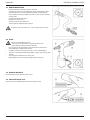
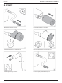
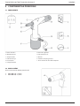
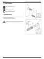
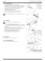
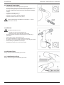
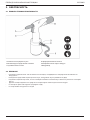
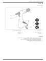
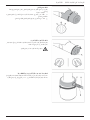
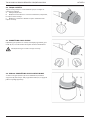
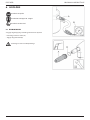
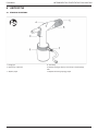
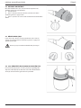
2. SAFETY
2.1 SAFETY INSTRUCTIONS
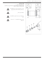
A Nose piece/front sleeve D Safety valve
B Mandrel collector E Air supply closing valve
C Trigger F Air connection
2.2 PERSONS
• Use safety goggles. This also applies to persons in the immediate surroundings.
• Use hearing protection when the sound level exceeds 85 dB(A).
• Use safety gloves, certain blind rivets can become very warm at some places.
• Keep your ngers away from the front when connecting the compressed air.
• Do not look straight into the tool (front and rear).
• Never direct the tool at persons.
ORIGINAL INSTRUCTION ENGLISH

6
2.3 WORK ENVIRONMENT
• Keep the work environment clean and neat.
• Use dry, ltered and with anti-corrosive oil lubricated air. If not
available, put 0.1 ml (approximately 5 drops) of anti-corrosive
lubricating oil in air connection of tool three times each operating
day.
• Work in a frost-free environment.
• The connection to the tools is G1/4“.
A connection nipple has not been included.
Provide an appropriate solution yourself.
Set a constant air pressure to 5 - 7 bars (maximum 7 bars).
2.4 TOOLS
Never use the tools
- when the nose piece/front sleeve (A) is missing;
- when the mandrel collector (B) has not been positioned
• Check the tools for damage before connecting the air pressure.
• Keep the tools in an optimum condition.
• Switch o the closing valve (C) when the tools are not used.
• Make sure that the exible connection hose (D) is not pressurised
when disconnecting.
• Do not modify the tools in any way.
• Only use the device for appropriate purposes.
2.5 DATE CODE
This is the place of the Date Code (A) of the tools.
2.6 TYPE IDENTIFICATION
This is the place of the type identi cation (B) of the tools.
ENGLISH ORIGINAL INSTRUCTION

7
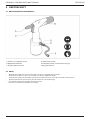
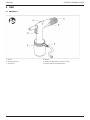
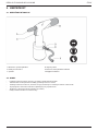
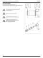
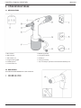
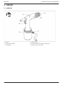
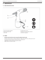
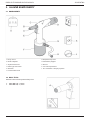
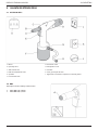
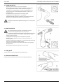
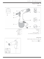
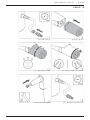
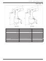
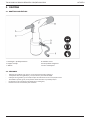
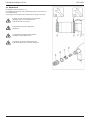
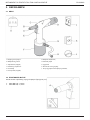
3. MAIN COMPONENTS
3.1 COMPONENTS
A Nose pieces** G Safety valve
B Front sleeve H Air connection
C Hydraulic body J Manual
D Mandrel collector K CE and guarantee form
E Trigger L CD with manual in various languages
F Pneumatic body
3.2 NOSE PIECES
The delivered box contains various nose pieces.
** EZM 1000: 3.0 – 5.0 mm
** EZM 2000: 4.0 – 6.4 mm
ORIGINAL INSTRUCTION ENGLISH

8
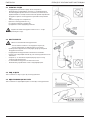
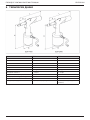
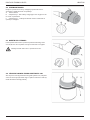
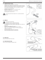
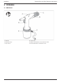
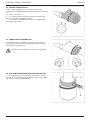
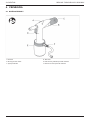
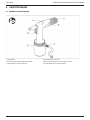
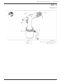
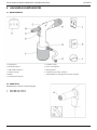
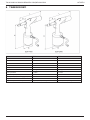
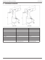
4. OPERATION
4.1 CONTROLS
A Bracket D Trigger
B Mandrel collector E 360° Revolvable air supply unit
C Air outlet F Air supply closing valve
ENGLISH ORIGINAL INSTRUCTION

9
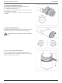
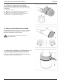
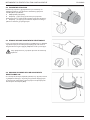
4.2 MANDREL COLLECTOR
The purpose of the mandrel collector is to collect the rest
mandrel. The collector can be placed in three positions.
A Position/remove.
B Lock – without extraction. Tilting the tools will make sure that
the mandrel will end up in the collector.
C Lock – with extraction. The rest mandrel is automatically
blown into the collector.
4.3 REVOLVABLE AIR OUTLET
The escaping air ow can be set using the revolvable air outlet (A)
such, that people experience a minimum of discomfort during
work.
Do not remove this air outlet from the mandrel collector.
4.4 360° REVOLVABLE AIR SUPPLY UNIT
When the air hose (A) causes discomfort during work, turn o
closing valve (B). After this the 360º revolvable unit (C) can be
turned into any required position.
ORIGINAL INSTRUCTION ENGLISH

10
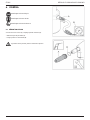
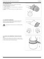
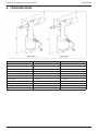
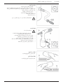
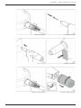
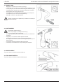
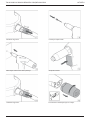
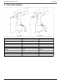
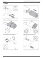
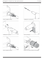
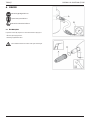
5. USE
Position the nipple (G1/4“). Position the mandrel collector.
Set the mandrel collector (see 4.2). Set the revolvable air outlet (see 4.3).
Mount the correct nose piece. Set the correct air pressure (see 2.3).
ENGLISH ORIGINAL INSTRUCTION

11
Turn on the closing valve. Position the blind rivet.
Position the tools. Press the trigger.
Turn o the closing valve. Empty the mandrel collector after use.
ORIGINAL INSTRUCTION ENGLISH

12
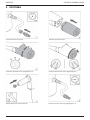
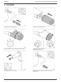
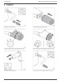
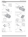
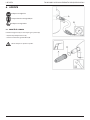
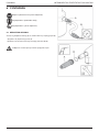
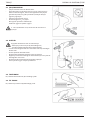
6. MAINTENANCE
Use safety goggles
Use hearing protection
Use safety gloves
6.1 FRONT SLEEVE
Turn o the closing valve (A) and disconnect the air supply (B).
- Remove the front sleeve (A).
- Pay attention to the o-ring (B).
Clean the inside using an air blow gun.
ENGLISH ORIGINAL INSTRUCTION

13
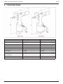
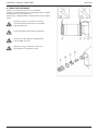
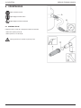
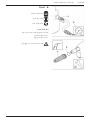
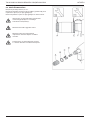
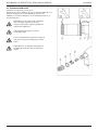
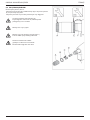
6.2 CLAMPING JAWS
Remove the front sleeve, see 6.1.
Remove the clamping sleeve (A) and the Te on ring (B), the 2
clamping jaws (C) and the jaw pusher (D).
Clean the clamping jaws and the jaw pusher or replace them.
Make sure that the spanner does not slip o
the locking nut (E). This may damage the
hydraulic piston rod (F).
Mounting is done in reverse order.
When mounting, lightly spray the inside of
the clamping sleeve with Te on spray.
Make sure that the locking nut is positioned
between 19-20 mm from the hydraulic body.
ORIGINAL INSTRUCTION ENGLISH

14
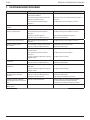
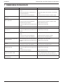
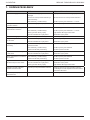
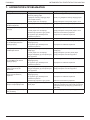
7. TROUBLE SHOOTING
Problem Cause Corrective action
The tool does not work The tool has not been connected to
the air connection
Connect the tool to the air connection
The air supply closing valve is still
closed
Open the air supply closing valve
There is insu cient air pressure Use the correct air pressure 5-7 bar
Air is coming out of the safety
valve
The air pressure is too high Use the correct air pressure 5-7 bar
There is no or insu cient
extraction
The extraction has not been turned on Check the position of the mandrel collector
There is insu cient air pressure Use the correct air pressure 5-7 bar
The mandrel collector is full Empty the mandrel collector
The tool is blocked by rest mandrels Remove the rest mandrel
The trigger does not work There is insu cient air pressure Use the correct air pressure 5-7 bar
The blind rivet cannot be
placed into the nose piece
The incorrect nose piece has been
mounted
Mount the correct nose piece
The tool is blocked by rest mandrels Remove the rest mandrel
The blind rivet is not set
correctly
Contaminated or worn clamping jaws Clear or replace the clamping jaws
There is insu cient air pressure Use the correct air pressure
The capacity of the tool has been
exceeded
Use the correct tool
The rest mandrel does not
release from the nose piece
The incorrect nose piece has been
mounted
Mount the correct nose piece
The tool is blocked by rest mandrels Remove the rest mandrel
During setting the rivet
mandrel does not break
There is insu cient air pressure Use the correct air pressure
The capacity of the tool has been
exceeded
Use the correct tool
The rest mandrel is not
extracted into the mandrel
collector
The incorrect nose piece has been
mounted
Mount the correct nose piece
The tool is blocked by rest mandrels Remove the rest mandrel
The mandrel collector is full Empty the mandrel collector
The air supply unit cannot be
turned 360°
The tool is still under air pressure Close the air supply closing valve and
depressurize the tool by turning on the
extraction or by operating the trigger
The tool does not perform well
consistently
Contact a service centre
ENGLISH ORIGINAL INSTRUCTION

15
8. TECHNICAL DATA
EZM 1000 EZM 2000
H 264 mm 275 mm
L 272 mm 272 mm
ø D 102 mm 125 mm
P 70 mm 70 mm
ø S 23 mm 23 mm
Weight 1,25 kg 1,65 kg
Air pressure 5-7 bars 5-7 bars
Pull force (6 bars) 7.3 kN 12.5 kN
Air consumption (per stroke) 1.5 l 2.0 l
Stroke 17 mm 21 mm
Capacity (standard blind rivet) ø 3.0 – 5.0 mm (stainless steel) ø 4.0 – 6.4 mm (stainless steel)
ORIGINAL INSTRUCTION ENGLISH

16
9. EC DECLARATION OF CONFORMITY
We,
Rivet Factory Group s. r. o.
Lannova 2061/8
110 00 Praha 1, Nové Město,
declare under our sole responsibility that the product:
Description: HYDROPNEUMATIC RIVETING TOOL
Model: EZM1000, EZM2000
To which this declaration relates is in conformity with the following harmonized standards
Safety:
Machinery Directive: ČSN EN ISO 11148-1:2015
Technical documentation is compiled in accordance with Annex 1, section 1.7.4.1, of the following Directive: 2006/42/EC
The Machinery Directive (Statutory Instruments 2008 No 1597 - The Supply of Machinery (Safety) Regulations).
The undersigned makes this declaration on behalf of Rivet Factory Group
Bc. Ondřej Slezák, CEO
Rivet Factory Group s. r. o.
Lannova 2061/8
110 00 Praha 1, Nové Město
Place of Issue: Drtinovo náměstí 171, 547 01 Náchod, Czech republic
Date of Issue: 11. 6. 2021
The undersigned is responsible for compilation of the technical le for products sold in the European Union and makes this
declaration on behalf of STANLEY Engineered Fastening.
Matthias Appel
Team Leader Technical Documentation
Stanley Engineered Fastening, Tucker GmbH, Max-Eyth-Str.1,
35394 Gießen, Germany
This machinery is in conformity with
Machinery Directive 2006/42/EC
ENGLISH ORIGINAL INSTRUCTION

17
10. UK DECLARATION OF CONFORMITY
We,
Rivet Factory Group s. r. o.
Lannova 2061/8
110 00 Praha 1, Nové Město
declare under our sole responsibility that the product:
Description: HYDROPNEUMATIC RIVETING TOOL
Model: EZM1000, EZM2000
to which this declaration relates is in conformity with the following designated standards:
Safety:
The Supply of Machinery (Safety) Regulations 2008 S.I. 2008/1597 (as amended):
Designated Standards ČSN EN ISO 11148-1:2015
Technical documentation is compiled in accordance with the Supply of Machinery (Safety) Regulations 2008, S.I. 2008/1597
(as amended).
The undersigned makes this declaration on behalf of Rivet Factory Group
Bc. Ondřej Slezák, CEO
Rivet Factory Group s. r. o.
Lannova 2061/8
110 00 Praha 1, Nové Město
Place of Issue: Drtinovo náměstí 171, 547 01 Náchod, Czech republic
Date of Issue: 11. 6. 2021
The undersigned is responsible for compilation of the technical le for products sold in the United Kingdom and makes this
declaration on behalf of Stanley Engineered Fastening.
A. K. Seewraj
Director of Engineering, UK
Avdel UK Limited, Stanley House, Works Road, Letchworth Garden City, Hertfordshire,
SG6 1JY UNITED KINGDOM
This machinery is in conformity with
Supply of Machinery (Safety) Regulations 2008,
S.I. 2008/1597 (as amended)
ORIGINAL INSTRUCTION ENGLISH

18
ENGLISH ORIGINAL INSTRUCTION

1
©2021 STANLEY Black & Decker
.
/
( ) STANLEY Engineered
Fastening. ,
. STANLEY Engineered Fastening
. ,
STANLEY Engineered Fastening. , STANLEY Engineered Fastening
, .
. , STANLEY Engineered Fastening
, .
STANLEY Engineered Fastening , ,
. , , .., STANLEY
Engineered Fastening, ,
.
1. . . . . . . . . . . . . . . . . . . . . . . . . . . . . . . . . . . . . . . . . . . . . . . . . . . . . . . . . . . . . . . . . . . . . . . .2
1.1 . . . . . . . . . . . . . . . . . . . . . . . . . . . . . . . . . . . . . . . . . . . . . . . . . . . . . . . . . . . . . . . . . . . . . . . 2
1.2 . . . . . . . . . . . . . . . . . . . . . . . . . . . . . . . . . . . . . . . . . . . . . . . . . . . . . . . . . . . . . . . . . . . . . . . . . . . . . . . 2
1.3 . . . . . . . . . . . . . . . . . . . . . . . . . . . . . . . . . . . . . . . . . . . . . . . . . . . . . . . . . . . . . . . . . . . . . . . . . . . . . . . . . 3
1.4 . . . . . . . . . . . . . . . . . . . . . . . . . . . . . . . . . . . . . . . . . . . . . . . . . . . . . . . . . . . . . . . 3
1.5 . . . . . . . . . . . . . . . . . . . . . . . . . . . . . . . . . . . . . . . . . . . . . . . . . . . . . . . . . . . . . . . . . . . . . . . . . . . . . . . 3
1.6 . . . . . . . . . . . . . . . . . . . . . . . . . . . . . . . . . . . . . . . . . . . . . . . . . . . . . . . . . . . . . . . . . . . . . 3
1.7 . . . . . . . . . . . . . . . . . . . . . . . . . . . . . . . . . . . . . . . . . . . . . . . . . . . . . . . . . . . . . . . . . . . . . . . . . . . . . . . . . . . . . 4
1.8 . . . . . . . . . . . . . . . . . . . . . . . . . . . . . . . . . . . . . . . . . . . . . . . . . . . . . . . . . . . . . . . . . . . . . . . . . . . . . . . 4
1.9 . . . . . . . . . 4
2. . . . . . . . . . . . . . . . . . . . . . . . . . . . . . . . . . . . . . . . . . . . . . . . . . . . . . . . . . . . . . . . . . . . . . . . . . . . . . . . . . . . . . . . . .5
2.1 . . . . . . . . . . . . . . . . . . . . . . . . . . . . . . . . . . . . . . . . . . . . . . . . . . . . . . . . . . . . . . . . . . . . . . . . . . 5
2.2 . . . . . . . . . . . . . . . . . . . . . . . . . . . . . . . . . . . . . . . . . . . . . . . . . . . . . . . . . . . . . . . . . . . . . . . . . . . . . . . . . . . . . . . . . . . . . . . . . . . . . . 5
2.3 . . . . . . . . . . . . . . . . . . . . . . . . . . . . . . . . . . . . . . . . . . . . . . . . . . . . . . . . . . . . . . . . . . . . . . . . . . . . . . . . . . . . . . . . . . . 6
2.4 . . . . . . . . . . . . . . . . . . . . . . . . . . . . . . . . . . . . . . . . . . . . . . . . . . . . . . . . . . . . . . . . . . . . . . . . . . . . . . . . . . . . . . . . . . . . 6
2.5 . . . . . . . . . . . . . . . . . . . . . . . . . . . . . . . . . . . . . . . . . . . . . . . . . . . . . . . . . . . . . . . . . . . . . . . . . . . . . . . . . . . . . . . . . . . . . . . 6
2.6 . . . . . . . . . . . . . . . . . . . . . . . . . . . . . . . . . . . . . . . . . . . . . . . . . . . . . . . . . . . . . . . . . . . . . . . . . . . . . . . 6
3. . . . . . . . . . . . . . . . . . . . . . . . . . . . . . . . . . . . . . . . . . . . . . . . . . . . . . . . . . . . . . . . . . . . . . . . . . . . . . . . . .7
3.1 . . . . . . . . . . . . . . . . . . . . . . . . . . . . . . . . . . . . . . . . . . . . . . . . . . . . . . . . . . . . . . . . . . . . . . . . . . . . . . . . . . . . . . . . . . . . . 7
3.2 . . . . . . . . . . . . . . . . . . . . . . . . . . . . . . . . . . . . . . . . . . . . . . . . . . . . . . . . . . . . . . . . . . . . . . . . . . . . . . . . . . . . . . . 7
4. . . . . . . . . . . . . . . . . . . . . . . . . . . . . . . . . . . . . . . . . . . . . . . . . . . . . . . . . . . . . . . . . . . . . . . . . . . . . . . . . . . . . . . . . . . . . . . . .8
4.1 . . . . . . . . . . . . . . . . . . . . . . . . . . . . . . . . . . . . . . . . . . . . . . . . . . . . . . . . . . . . . . . . . . . . . . . . . . . . . . . . . . . . . . . . . . . . . . . . . 8
4.2 . . . . . . . . . . . . . . . . . . . . . . . . . . . . . . . . . . . . . . . . . . . . . . . . . . . . . . . . . . . . . . . . . . . . . . . . . . . . . . . . . . . . . 9
4.3 . . . . . . . . . . . . . . . . . . . . . . . . . . . . . . . . . . . . . . . . . . . . . . . . . . . . . . . . . . . . . . . . . . . . . . . . . . . . 9
4.4 360° . . . . . . . . . . . . . . . . . . . . . . . . . . . . . . . . . . . . . . . . . . . . . . . . . . . . . . . . . 9
5. . . . . . . . . . . . . . . . . . . . . . . . . . . . . . . . . . . . . . . . . . . . . . . . . . . . . . . . . . . . . . . . . . . . . . . . . . . . . . . . . . . . . . . . . . . . 10
6. . . . . . . . . . . . . . . . . . . . . . . . . . . . . . . . . . . . . . . . . . . . . . . . . . . . . . . . . . . . . . . . . . . . . . . . . . . . . . . . . . . . . . . . . 12
6.1 . . . . . . . . . . . . . . . . . . . . . . . . . . . . . . . . . . . . . . . . . . . . . . . . . . . . . . . . . . . . . . . . . . . . . . . . . . . . . . . . . . . . . . . . . .12
6.2 . . . . . . . . . . . . . . . . . . . . . . . . . . . . . . . . . . . . . . . . . . . . . . . . . . . . . . . . . . . . . . . . . . . . . . . . . . . . . . . . . . . . .13
7. . . . . . . . . . . . . . . . . . . . . . . . . . . . . . . . . . . . . . . . . . . . . . . . . . . . . . . . . . . . . . . . . 14
8. . . . . . . . . . . . . . . . . . . . . . . . . . . . . . . . . . . . . . . . . . . . . . . . . . . . . . . . . . . . . . . . . . . . . . . . . . . . . . . . . . 15
9. . . . . . . . . . . . . . . . . . . . . . . . . . . . . . . . . . . . . . . . . . . . . . . . . . . . . . . . . . . . . . . . . . . 16
10. . . . . . . . . . . . . . . . . . . . . . . . . . . . . . . . . . . . . . . . . 17
Sayfa yükleniyor...
Sayfa yükleniyor...
Sayfa yükleniyor...
Sayfa yükleniyor...
Sayfa yükleniyor...
Sayfa yükleniyor...
Sayfa yükleniyor...
Sayfa yükleniyor...
Sayfa yükleniyor...
Sayfa yükleniyor...
Sayfa yükleniyor...
Sayfa yükleniyor...
Sayfa yükleniyor...
Sayfa yükleniyor...
Sayfa yükleniyor...
Sayfa yükleniyor...
Sayfa yükleniyor...
Sayfa yükleniyor...
Sayfa yükleniyor...
Sayfa yükleniyor...
Sayfa yükleniyor...
Sayfa yükleniyor...
Sayfa yükleniyor...
Sayfa yükleniyor...
Sayfa yükleniyor...
Sayfa yükleniyor...
Sayfa yükleniyor...
Sayfa yükleniyor...
Sayfa yükleniyor...
Sayfa yükleniyor...
Sayfa yükleniyor...
Sayfa yükleniyor...
Sayfa yükleniyor...
Sayfa yükleniyor...
Sayfa yükleniyor...
Sayfa yükleniyor...
Sayfa yükleniyor...
Sayfa yükleniyor...
Sayfa yükleniyor...
Sayfa yükleniyor...
Sayfa yükleniyor...
Sayfa yükleniyor...
Sayfa yükleniyor...
Sayfa yükleniyor...
Sayfa yükleniyor...
Sayfa yükleniyor...
Sayfa yükleniyor...
Sayfa yükleniyor...
Sayfa yükleniyor...
Sayfa yükleniyor...
Sayfa yükleniyor...
Sayfa yükleniyor...
Sayfa yükleniyor...
Sayfa yükleniyor...
Sayfa yükleniyor...
Sayfa yükleniyor...
Sayfa yükleniyor...
Sayfa yükleniyor...
Sayfa yükleniyor...
Sayfa yükleniyor...
Sayfa yükleniyor...
Sayfa yükleniyor...
Sayfa yükleniyor...
Sayfa yükleniyor...
Sayfa yükleniyor...
Sayfa yükleniyor...
Sayfa yükleniyor...
Sayfa yükleniyor...
Sayfa yükleniyor...
Sayfa yükleniyor...
Sayfa yükleniyor...
Sayfa yükleniyor...
Sayfa yükleniyor...
Sayfa yükleniyor...
Sayfa yükleniyor...
Sayfa yükleniyor...
Sayfa yükleniyor...
Sayfa yükleniyor...
Sayfa yükleniyor...
Sayfa yükleniyor...
Sayfa yükleniyor...
Sayfa yükleniyor...
Sayfa yükleniyor...
Sayfa yükleniyor...
Sayfa yükleniyor...
Sayfa yükleniyor...
Sayfa yükleniyor...
Sayfa yükleniyor...
Sayfa yükleniyor...
Sayfa yükleniyor...
Sayfa yükleniyor...
Sayfa yükleniyor...
Sayfa yükleniyor...
Sayfa yükleniyor...
Sayfa yükleniyor...
Sayfa yükleniyor...
Sayfa yükleniyor...
Sayfa yükleniyor...
Sayfa yükleniyor...
Sayfa yükleniyor...
Sayfa yükleniyor...
Sayfa yükleniyor...
Sayfa yükleniyor...
Sayfa yükleniyor...
Sayfa yükleniyor...
Sayfa yükleniyor...
Sayfa yükleniyor...
Sayfa yükleniyor...
Sayfa yükleniyor...
Sayfa yükleniyor...
Sayfa yükleniyor...
Sayfa yükleniyor...
Sayfa yükleniyor...
Sayfa yükleniyor...
Sayfa yükleniyor...
Sayfa yükleniyor...
Sayfa yükleniyor...
Sayfa yükleniyor...
Sayfa yükleniyor...
Sayfa yükleniyor...
Sayfa yükleniyor...
Sayfa yükleniyor...
Sayfa yükleniyor...
Sayfa yükleniyor...
Sayfa yükleniyor...
Sayfa yükleniyor...
Sayfa yükleniyor...
Sayfa yükleniyor...
Sayfa yükleniyor...
Sayfa yükleniyor...
Sayfa yükleniyor...
Sayfa yükleniyor...
Sayfa yükleniyor...
Sayfa yükleniyor...
Sayfa yükleniyor...
Sayfa yükleniyor...
Sayfa yükleniyor...
Sayfa yükleniyor...
Sayfa yükleniyor...
Sayfa yükleniyor...
Sayfa yükleniyor...
Sayfa yükleniyor...
Sayfa yükleniyor...
Sayfa yükleniyor...
Sayfa yükleniyor...
Sayfa yükleniyor...
Sayfa yükleniyor...
Sayfa yükleniyor...
Sayfa yükleniyor...
Sayfa yükleniyor...
Sayfa yükleniyor...
Sayfa yükleniyor...
Sayfa yükleniyor...
Sayfa yükleniyor...
Sayfa yükleniyor...
Sayfa yükleniyor...
Sayfa yükleniyor...
Sayfa yükleniyor...
Sayfa yükleniyor...
Sayfa yükleniyor...
Sayfa yükleniyor...
Sayfa yükleniyor...
Sayfa yükleniyor...
Sayfa yükleniyor...
Sayfa yükleniyor...
Sayfa yükleniyor...
Sayfa yükleniyor...
Sayfa yükleniyor...
Sayfa yükleniyor...
Sayfa yükleniyor...
Sayfa yükleniyor...
Sayfa yükleniyor...
Sayfa yükleniyor...
Sayfa yükleniyor...
Sayfa yükleniyor...
Sayfa yükleniyor...
Sayfa yükleniyor...
Sayfa yükleniyor...
Sayfa yükleniyor...
Sayfa yükleniyor...
Sayfa yükleniyor...
Sayfa yükleniyor...
Sayfa yükleniyor...
Sayfa yükleniyor...
Sayfa yükleniyor...
Sayfa yükleniyor...
Sayfa yükleniyor...
Sayfa yükleniyor...
Sayfa yükleniyor...
Sayfa yükleniyor...
Sayfa yükleniyor...
Sayfa yükleniyor...
Sayfa yükleniyor...
Sayfa yükleniyor...
Sayfa yükleniyor...
Sayfa yükleniyor...
Sayfa yükleniyor...
Sayfa yükleniyor...
Sayfa yükleniyor...
Sayfa yükleniyor...
Sayfa yükleniyor...
Sayfa yükleniyor...
Sayfa yükleniyor...
Sayfa yükleniyor...
Sayfa yükleniyor...
Sayfa yükleniyor...
Sayfa yükleniyor...
Sayfa yükleniyor...
Sayfa yükleniyor...
Sayfa yükleniyor...
Sayfa yükleniyor...
Sayfa yükleniyor...
Sayfa yükleniyor...
Sayfa yükleniyor...
Sayfa yükleniyor...
Sayfa yükleniyor...
Sayfa yükleniyor...
Sayfa yükleniyor...
Sayfa yükleniyor...
Sayfa yükleniyor...
Sayfa yükleniyor...
Sayfa yükleniyor...
Sayfa yükleniyor...
Sayfa yükleniyor...
Sayfa yükleniyor...
Sayfa yükleniyor...
Sayfa yükleniyor...
Sayfa yükleniyor...
Sayfa yükleniyor...
Sayfa yükleniyor...
Sayfa yükleniyor...
Sayfa yükleniyor...
Sayfa yükleniyor...
Sayfa yükleniyor...
Sayfa yükleniyor...
Sayfa yükleniyor...
Sayfa yükleniyor...
Sayfa yükleniyor...
Sayfa yükleniyor...
Sayfa yükleniyor...
Sayfa yükleniyor...
Sayfa yükleniyor...
Sayfa yükleniyor...
Sayfa yükleniyor...
Sayfa yükleniyor...
Sayfa yükleniyor...
Sayfa yükleniyor...
Sayfa yükleniyor...
Sayfa yükleniyor...
Sayfa yükleniyor...
Sayfa yükleniyor...
-
 1
1
-
 2
2
-
 3
3
-
 4
4
-
 5
5
-
 6
6
-
 7
7
-
 8
8
-
 9
9
-
 10
10
-
 11
11
-
 12
12
-
 13
13
-
 14
14
-
 15
15
-
 16
16
-
 17
17
-
 18
18
-
 19
19
-
 20
20
-
 21
21
-
 22
22
-
 23
23
-
 24
24
-
 25
25
-
 26
26
-
 27
27
-
 28
28
-
 29
29
-
 30
30
-
 31
31
-
 32
32
-
 33
33
-
 34
34
-
 35
35
-
 36
36
-
 37
37
-
 38
38
-
 39
39
-
 40
40
-
 41
41
-
 42
42
-
 43
43
-
 44
44
-
 45
45
-
 46
46
-
 47
47
-
 48
48
-
 49
49
-
 50
50
-
 51
51
-
 52
52
-
 53
53
-
 54
54
-
 55
55
-
 56
56
-
 57
57
-
 58
58
-
 59
59
-
 60
60
-
 61
61
-
 62
62
-
 63
63
-
 64
64
-
 65
65
-
 66
66
-
 67
67
-
 68
68
-
 69
69
-
 70
70
-
 71
71
-
 72
72
-
 73
73
-
 74
74
-
 75
75
-
 76
76
-
 77
77
-
 78
78
-
 79
79
-
 80
80
-
 81
81
-
 82
82
-
 83
83
-
 84
84
-
 85
85
-
 86
86
-
 87
87
-
 88
88
-
 89
89
-
 90
90
-
 91
91
-
 92
92
-
 93
93
-
 94
94
-
 95
95
-
 96
96
-
 97
97
-
 98
98
-
 99
99
-
 100
100
-
 101
101
-
 102
102
-
 103
103
-
 104
104
-
 105
105
-
 106
106
-
 107
107
-
 108
108
-
 109
109
-
 110
110
-
 111
111
-
 112
112
-
 113
113
-
 114
114
-
 115
115
-
 116
116
-
 117
117
-
 118
118
-
 119
119
-
 120
120
-
 121
121
-
 122
122
-
 123
123
-
 124
124
-
 125
125
-
 126
126
-
 127
127
-
 128
128
-
 129
129
-
 130
130
-
 131
131
-
 132
132
-
 133
133
-
 134
134
-
 135
135
-
 136
136
-
 137
137
-
 138
138
-
 139
139
-
 140
140
-
 141
141
-
 142
142
-
 143
143
-
 144
144
-
 145
145
-
 146
146
-
 147
147
-
 148
148
-
 149
149
-
 150
150
-
 151
151
-
 152
152
-
 153
153
-
 154
154
-
 155
155
-
 156
156
-
 157
157
-
 158
158
-
 159
159
-
 160
160
-
 161
161
-
 162
162
-
 163
163
-
 164
164
-
 165
165
-
 166
166
-
 167
167
-
 168
168
-
 169
169
-
 170
170
-
 171
171
-
 172
172
-
 173
173
-
 174
174
-
 175
175
-
 176
176
-
 177
177
-
 178
178
-
 179
179
-
 180
180
-
 181
181
-
 182
182
-
 183
183
-
 184
184
-
 185
185
-
 186
186
-
 187
187
-
 188
188
-
 189
189
-
 190
190
-
 191
191
-
 192
192
-
 193
193
-
 194
194
-
 195
195
-
 196
196
-
 197
197
-
 198
198
-
 199
199
-
 200
200
-
 201
201
-
 202
202
-
 203
203
-
 204
204
-
 205
205
-
 206
206
-
 207
207
-
 208
208
-
 209
209
-
 210
210
-
 211
211
-
 212
212
-
 213
213
-
 214
214
-
 215
215
-
 216
216
-
 217
217
-
 218
218
-
 219
219
-
 220
220
-
 221
221
-
 222
222
-
 223
223
-
 224
224
-
 225
225
-
 226
226
-
 227
227
-
 228
228
-
 229
229
-
 230
230
-
 231
231
-
 232
232
-
 233
233
-
 234
234
-
 235
235
-
 236
236
-
 237
237
-
 238
238
-
 239
239
-
 240
240
-
 241
241
-
 242
242
-
 243
243
-
 244
244
-
 245
245
-
 246
246
-
 247
247
-
 248
248
-
 249
249
-
 250
250
-
 251
251
-
 252
252
-
 253
253
-
 254
254
-
 255
255
-
 256
256
-
 257
257
-
 258
258
-
 259
259
-
 260
260
-
 261
261
-
 262
262
-
 263
263
-
 264
264
-
 265
265
-
 266
266
-
 267
267
-
 268
268
-
 269
269
-
 270
270
-
 271
271


diğer dillerde
- eesti: Stanley EZM 1000 Kasutusjuhend
- slovenčina: Stanley EZM 1000 Používateľská príručka
- română: Stanley EZM 1000 Manual de utilizare