Yamaha HTR-5140RDS Kullanım kılavuzu
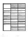
- Kategori
- Alıcı
- Tip
- Kullanım kılavuzu

HTR-5140RDS
Natural Sound AV Receiver
Ampli-Tuner Audio-Video
OWNER’S MANUAL
MODE D’EMPLOI
BEDIENUNGSANLEITUNG
BRUKSANVISNING
MANUALE DI ISTRUZIONI
MANUAL DE INSTRUCCIONES
GEBRUIKSAANWIJZING
G
Printed in Malaysia ID
V343270
YAMAHA ELECTRONICS CORPORATION, USA 6660 ORANGETHORPE AVE., BUENA PARK, CALIF. 90620, U.S.A.
YAMAHA CANADA MUSIC LTD. 135 MILNER AVE., SCARBOROUGH, ONTARIO M1S 3R1, CANADA
YAMAHA ELECTRONIK EUROPA G.m.b.H. SIEMENSSTR. 22-34, 25462 RELLINGEN BEI HAMBURG, F.R. OF GERMANY
YAMAHA ELECTRONIQUE FRANCE S.A. RUE AMBROISE CROIZAT BP70 CROISSY-BEAUBOURG 77312 MARNE-LA-VALLEE CEDEX02, FRANCE
YAMAHA ELECTRONICS (UK) LTD. YAMAHA HOUSE, 200 RICKMANSWORTH ROAD WATFORD, HERTS WD1 7JS, ENGLAND
YAMAHA SCANDINAVIA A.B. J A WETTERGRENS GATA 1, BOX 30053, 400 43 VÄSTRA FRÖLUNDA, SWEDEN
YAMAHA MUSIC AUSTRALIA PTY, LTD. 17-33 MARKET ST., SOUTH MELBOURNE, 3205 VIC., AUSTRALIA
HTR-5140RDS
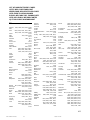
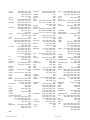
CD PLAYER
Accuphase 0315
Adc 0865
Adcom 0785, 1015
Akai 0115, 0125, 0725, 0735,
0745, 0935, 1155
Arcam 1875
Arcam-Rotel 0165
Audio-Technica 0835
Audiosonic 0155
Awia 1105, 1235, 1245,
1765, 1915, 1935
BSR 0875
California Audio Lab 1075
Carrera 0555, 0875
Carver 0825, 1415
Cyrus-Rotel 0205
Denon 0045, 0955, 1045,
1595, 1795, 1805
Dual 1005
Elin 0185
Emerson 1015, 1285, 1675
Fisher 0105, 0595, 0605,
0825, 1165, 1175
Genexxa 0525, 0825, 0855, 0875,
0995, 1265, 1285, 1345,
1355, 1485, 1575, 1675,
1715, 1825
GoldStar 0555, 1185, 1195, 1585
Grundig 0175
Harman Kardon 0495, 0565, 0325,
1135, 1145, 1155
Hitachi 0065, 0585, 0685, 0945,
1005, 1015, 1225, 1545
Innovation 1995, 2005, 2015
ITT-Nokia 0185
JVC 0385, 0395, 0455, 0575, 0585
Karcher 0485
Kenwood 0025, 0055, 0145, 0215,
0595, 0675, 0695, 0705,
0715, 0925, 1355, 1485,
1575, 1675, 1715, 1825
Korting 0175
Lifetec 2015
Light Control 1155, 1645, 1655, 1665
Linn 0165, 1875
Luxman 0265, 0275, 0795, 0805,
1295, 1305, 1555, 1925
Luxor 0185, 1895, 1905
Magnavox 1865, 1875
Marantz 0165, 0175, 0545, 0665,
1275, 1335, 1405, 1505,
1875, 1955
Matsushita 1095, 1605
MCS 0535
Medion 0075, 1995, 2005, 2015
Memorex 0525, 1015, 1265, 1275,
1285, 1675
MGA 1125
Micromaxx 2015
Mission 0165, 1875
Mitsubishi 1125, 1205
NAD 0255, 0285, 0295, 0305, 0345,
0135, 0755, 0765, 1315, 1325
Nakamichi 0635, 0645, 1565
NEC 0405, 0535, 0775, 0785
Neckerman 0155, 0225
Nikko 0835, 1165
Oceanic 0185
Okano 0155, 0225
Onkyo 0885, 1385, 1425, 1455, 1515
Panasonic 1055, 1075, 1615, 1625
Philips 0165, 0175, 0195, 1865, 1875
Pioneer 0095, 0335, 0425, 0435, 0445,
0525, 0855, 1035, 1945
Proton 0905, 1875
Quasar 1075
Radiola 1845, 1855
Radiotone 0485
Realistic 0825, 1015, 1265,
1275, 1285, 1575
Rotel 1875
Saba 1005
SAE 1875
Salora 0185
Sansui 0415, 0965, 0975, 0985,
1255, 1675, 1875
Sanyo 0625, 0825, 0845, 0915
Schneider 1845, 1855
Scott 1285, 1675
Sharp 0025, 0035, 1025, 1115, 1275,
1635, 1785, 1815, 1825, 1835
Sherwood 1275, 1445
Siemens 1085
Signature 1155
Sony 0345, 0355, 0365, 0375, 0865,
1685, 1695, 1705, 1715, 1725,
1735, 1745
Sytvania 1875
Tandberg 1885
Tashiko 1525
TCM 1985, 2015
Teac 0235, 0245, 1275, 1365, 1375,
1395, 1435, 1465, 1475
Technics 0465, 0475, 1065, 1075, 1625
Telefunken 1005
Theta Digital 1865
Thomson 1005
Toshiba 0755, 0765
Vector Research 0555, 0865
Victor 0575
Yamaha 0005, 0015, 0895, 1815
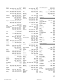
MD RECORDER
Yamaha 0024
TAPE DECK
Akai 0124
Denon 0204
Grundig 0134
Harman 0044
JVC 0194
Kenwood 0164
Korting 0134
Luxman 0054, 0064, 0074, 0084
Marantz 0134, 0144
NAD 0174
Onkyo 0184
Philips 0134, 0144, 0154
Pioneer 0034, 0114
Sony 0094, 0104
Yamaha 0004, 0014
00HTR-5140RDS-cv1/4(AL) 6/22/99, 1:31 PM1

2
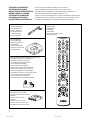
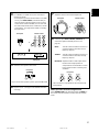
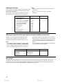
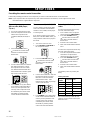
SUPPLIED ACCESSORIES
ACCESSOIRES FOURNIS
MITGELIEFERTE ZUBEHÖRTEILE
MEDFÖLJANDE TILLBEHÖR
ACCESSORI IN DOTAZIONE
ACCESORIOS INCLUIDOS
BIJGELEVERDE ACCESSOIRES
• After unpacking, check that the following parts are included.
• Après le déballage, vérifier que les pièces suivantes sont incluses.
• Nach dem Auspacken überprüfen, ob die folgenden Teile vorhanden sind.
• Kontrollera efter uppackningen att följande delar finns med.
•
Verificare che tutte le parti seguenti siano contenute nell’imballaggio dell’apparecchio.
• Desembalar el aparato y verificar que los siguientes accesorios están en la caja.
• Controleer na het uitpakken of de volgende onderdelen voorhanden zijn.
• Indoor FM Antenna
• Antenne FM intérieure
• UKW-Innenantenne
• Inomhus-FM-antenn
• Antenna FM interna
• Antena FM interior
• FM-binnenantenne
• AM Loop Antenna
• Cadre-antenne AM
• MW-Rahmenantenne
• AM-ramantenn
• Antenna AM ad anello
• Antena de cuadro de AM
• AM-raamantenne
• 75-ohm/300-ohm antenna adapter (U.K. model only)
• Adaptateur d’antenne 75 ohms/300 ohms
(Modèle Royaume-Uni seulement)
• 75-Ohm/300-Ohm Antennenstecker
(nur Großbritannien-Modell)
• 75 ohm/300 ohm antennadapter
(gäller endast modellen för Storbritannien)
• Adattatore per antenna da 75 e 300 ohm
(Soltanto il modello per la Gran Bretagna)
• Adaptador de antena de 75-ohmios/300-ohmios
(Sólo el modelo para el Reino Unido)
• 75 ohm/300 ohm antenneadapter
(Alleen modellen voor Verenigd Koninkrijk)
• Batteries (size AAA, R03, UM-4)
• Piles (taille AAA, R03, UM-4)
• Batterien (Größe AAA, R03, UM-4)
• Batterier
(storlek AAA, R03, UM-4)
• Batterie
(formato AAA, R03, UM-4)
• Pilas (tamaño AAA, R03, UM-4)
• Batterijen (maat AAA, R03, UM-4)
• Remote control transmitter
• Télécommande
• Fernbedienung
• Fjärrkontroll
• Telecomando
• Transmisor de control remoto
• Afstandsbediening
01RX-V495RDS-1 6/22/99, 12:26 PM2

3
English
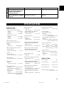
● 5-Channel Power Amplification
Minimum RMS Output Power
<0.04% THD, 20 Hz – 20 kHz>
Main: 60 W + 60 W (8 Ω)
Center: 60 W (8 Ω)
Rear: 60 W + 60 W (8 Ω)
● Digital Sound Field Processor
● Dolby Digital Decoder
● Dolby Pro Logic Surround Decoder
● CINEMA DSP: Theater-like Sound
Experience by the Combination of Dolby
Surround and YAMAHA DSP Technology
● 6-Channel External Decoder Input for DTS
and other future formats
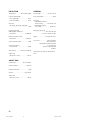
SUPPLIED ACCESSORIES........................................... 2
FEATURES .................................................................... 3
CAUTION ....................................................................... 4
●Introduction
FEATURES OF SOUND EFFECTS...............................5
CONTROLS AND THEIR FUNCTIONS ......................... 7
●Preparation
SPEAKER SETUP ....................................................... 12
CONNECTIONS........................................................... 14
ADJUSTMENTS
BEFORE USING THIS UNIT .................................. 21
●Basic Operation
BASIC OPERATIONS .................................................. 26
TUNING OPERATIONS ............................................... 30
RECEIVING RDS STATIONS ...................................... 35
SETTING THE SLEEP TIMER..................................... 40
●Information about DSP
USING THE DIGITAL SOUND FIELD
PROCESSOR (DSP) .............................................. 41
●Advanced Information
ADJUSTMENTS
IN THE “SET MENU” MODE...................................47
●Remote Control Transmitter
REMOTE CONTROL TRANSMITTER......................... 49
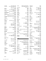
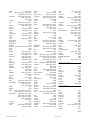
SETUP CODES ........................................................... 56
TROUBLESHOOTING ................................................. 57
SPECIFICATIONS .......................................................59
LIST OF MANUFACTURER’S CODES...................... 411
FEATURES
CONTENTS
● Automatic Input Balance Control for
Dolby Pro Logic Surround
● Test Tone Generator for Easier Speaker
Balance Adjustment
● Speaker Output Mode Changing
Capability
● 40-Station Random Access Preset Tuning
● Automatic Preset Tuning
● Preset Station Shifting Capability
(Preset Editing)
● Video Signal Input/Output Capability
● SLEEP Timer
● Universal Remote Control
Transmitter with Preset Manufacturer
Codes
01RX-V495RDS-1 6/22/99, 12:26 PM3

4
CAUTION: READ THIS BEFORE OPERATING YOUR UNIT.
1. To assure the finest performance, please read this manual
carefully. Keep it in a safe place for future reference.
2. Install this unit in a cool, dry, clean place – away from
windows, heat sources, sources of excessive vibration,
dust, moisture and cold. Avoid sources of humming
(transformers, motors). To prevent fire or electrical shock,
do not expose the unit to rain or water.
3. Never open the cabinet. If something drops into the set,
contact your dealer.
4. Do not use force on switches, controls or connection wires.
When moving the unit, first disconnect the power plug and
the wires connected to other equipment. Never pull the
wires themselves.
5. The openings on the unit cover assure proper ventilation of
the unit. If these openings are obstructed, the temperature
inside the unit will rise rapidly. Therefore, avoid placing
objects against these openings, and install the unit in a
well-ventilated area to prevent fire and damage.
Be sure to allow a space of at least 20 cm behind, 20 cm
on the both sides and 30 cm above the top panel of the unit
to prevent fire and damage.
6. The voltage used must be the same as that specified on
this unit. Using this unit with a higher voltage than
specified is dangerous and may result in fire or other
accidents. YAMAHA will not be held responsible for any
damage resulting from use of this unit with a voltage other
than specified.
7. Digital signals generated by this unit may interfere with
other equipment such as tuners, receivers or TVs. Move
this unit farther away from such equipment if interference is
observed.
8. Always set the VOLUME control to “
” before starting the
audio source play. Increase the volume gradually to an
appropriate level after playback has been started.
9. Do not attempt to clean the unit with chemical solvents; this
might damage the finish. Use a clean, dry cloth.
10. Be sure to read the “TROUBLESHOOTING” section
regarding common operating errors before concluding that
the unit is faulty.
11. When not planning to use this unit for long periods of time
(ie., vacation, etc.), disconnect the AC power plug from the
wall outlet.
12. To prevent lightning damage, disconnect the AC power
plug and disconnect the antenna cable when there is an
electrical storm.
13. Grounding or polarization – Precautions should be taken so
that the grounding or polarization of an appliance is not
defeated.
14. AC outlet
Do not connect audio equipment to the AC outlet on the
rear panel if that equipment requires more power than the
outlet is rated to provide.
For U.K. customers
If the socket outlets in the home are not suitable for the plug
supplied with this appliance, it should be cut off and an
appropriate 3 pin plug fitted. For details, refer to the instructions
described below.
Note: The plug severed from the mains lead must be
destroyed, as a plug with bared flexible cord is hazardous if
engaged in a live socket outlet.
Special Instructions for U.K. Model
IMPORTANT
THE WIRES IN MAINS LEAD ARE COLOURED IN
ACCORDANCE WITH THE FOLLOWING CODE:
Blue: NEUTRAL
Brown: LIVE
As the colours of the wires in the mains lead of this
apparatus may not correspond with the coloured markings
identifying the terminals in your plug, proceed as follows:
The wire which is coloured BLUE must be connected to the
terminal which is marked with the letter N or coloured
BLACK. The wire which is coloured BROWN must be
connected to the terminal which is marked with the letter L or
coloured RED.
Making sure that neither core is connected to the earth
terminal of the three pin plug.
This unit is not disconnected from the AC power source as
long as it is connected to the wall outlet, even if this unit
itself is turned off. This state is called the standby mode. In
this state, this unit is designed to consume a very small
quantity of power.
01RX-V495RDS-1 6/22/99, 12:26 PM4

5
English
FEATURES OF SOUND EFFECTS
Welcome to the exciting world of digital home entertainment.
This unit is one of the most complete and advanced AV
receivers available. Some of the more advanced features may
not be familiar to you, but they are easy to use. State-of-the-art
technologies such as Dolby Digital and Digital Theater Systems
(DTS) may be new to your home, but you have probably
experienced the amazing realism they bring to feature films in
theaters around the world.
To make the listening experience even more enjoyable, this unit
includes a number of exclusive, digitally created listening
environments known as digital sound fields. Choosing a sound
field program is like transporting yourself to such venues as an
outdoor arena, a European church, or a cozy jazz club. Take
some time now to read more about these features and enjoy
the new experiences this unit brings to your home theater.
Digital Sound Field Processing
What is it that makes live music so good? Today’s advanced
sound reproduction technology lets you get extremely close to
the sound of a live performance, but the chances are that you’ll
still notice something missing — the acoustic environment of
the live concert hall. Extensive research into the exact nature
of the sonic reflections that create the ambience of a large hall
has made it possible for YAMAHA engineers to bring you this
same sound to your listening room, so you’ll feel all the sound
of a live concert.
Furthermore, our technicians, armed with sophisticated
measuring equipment, have even made it possible to capture
the acoustics of a variety of actual concert halls, theaters, etc.
from around the world, to allow you to accurately re-create any
one of these live performance environments, all in your own
home.
Dolby Pro Logic Surround
Dolby Surround has been used in movie theaters since the mid-
seventies. It has also been available in home entertainment
systems since the late eighties and continues to be a popular
format for home theater systems. It uses four discrete channels
and five speakers to reproduce realistic and dynamic sound
effects: two main channels (left and right), a center channel for
dialog, and a rear channel for special sound effects. The rear
channel reproduces sound within a narrow frequency range.
Most video tapes and laser discs include Dolby Surround
encoding, as do many TV and cable broadcasts. The Dolby Pro
Logic Surround decoder built into this unit employs a digital
signal processing system that stabilizes each channel for even
more accurate sound positioning than is available with standard
analog processors.
Dolby Digital
The built-in Dolby Digital decoder leads you into a totally new
sound experience.
Dolby Digital is a new generation of multi-channel digital audio
technology, or the newest spatial sound processing format
developed for 35 mm-film movies by employing a new kind of
low bit-rate audio coding.
Dolby Digital is a digital surround sound system that provides
completely independent multi-channel audio to listeners. In
multi-channel form, Dolby Digital provides 5 full-range channels
in what is sometimes referred to as a “3/2” configuration: three
front channels (left, center and right), plus two surround
channels. A sixth bass-only effect channel is also provided for
output of LFE (low frequency effect), or low bass effects that
are independent of other channels. This channel is counted as
0.1, thus giving rise to the term 5.1 channels in total.
Compared to Dolby Pro Logic, which is referred to a “3/1”
system (left front, center, right front and just one surround
channel), Dolby Digital features two surround channels, called
stereo or split surrounds, each offering the same full-range
fidelity as the three front channels.
Sound of wide dynamic range reproduced by the 5 full-range
channels provides listeners with excitement that has never
been experienced before. Precise sound orientation by
discrete digital sound processing expands the realism that the
original movie possesses.
LD and DVD are home audio/video program source that could
benefit from Dolby Digital. In the near future, Dolby Digital will
also be applied to DBS, CATV and HDTV. The ongoing release
of Dolby Digital theatrical films now underway will provide an
immediate source of Dolby Digital encoded video software.
Introduction
01RX-V495RDS-1 6/22/99, 12:26 PM5

6
Manufactured under license from Dolby Laboratories. “Dolby”,
“Pro Logic” and the double-D symbol are trademarks of Dolby
Laboratories.
The following original functions make the surround-sound effect
of Dolby Digital become the most suitable for your audio
system and the listening conditions.
CINEMA DSP: Dolby Surround + DSP
The Dolby Surround sound system shows its full ability in a
large movie theater, because movie sounds are originally
designed to be reproduced in a large movie theater using many
speakers. It is difficult to create a sound environment similar to
that of a movie theater in your listening room, because the
room size, materials of inside walls, the number of speakers,
etc. of your listening room are very different from those of a
movie theater.
YAMAHA DSP technology made it possible to present you with
nearly the same sound experience as that of a large movie
theater in your listening room by compensating for the lack of
presence and dynamics in your listening room with its original
digital sound fields combined with the Dolby Surround sound
system.
CINEMA DSP
The YAMAHA “CINEMA DSP” logo indicates those programs
that are created by the combination of Dolby Surround and
YAMAHA DSP technology.
Dolby Pro Logic + 2 Digital Sound Fields
Digital sound fields are created on the presence side and the
rear surround side of the Dolby Pro Logic Surround-decoded
sound field, respectively. They create a wide acoustic
environment and emphasize the surround effect in the room,
letting you feel as much presence as if you are watching a
movie in a popular Dolby Stereo theater.
This combination is available when the DOLBY PRO LOGIC
ENHANCED/DOLBY DIGITAL ENHANCED, 70 mm MOVIE
THEATER/DIGITAL MOVIE THEATER or TV SPORTS sound
field program is selected, and the input signal of source is
analog, PCM audio or encoded with Dolby Digital sound in
2-channel.
Dolby Digital + 3 Digital Sound Fields
Digital sound fields are created on the presence side and the
independent left and right surround sides of the Dolby Digital-
decoded sound field, respectively. They create a wide
acoustic environment and strong surround effect in the room
without losing high-channel separation. With the wide
dynamic range of Dolby Digital sound, this sound field
combination lets you feel as if you are watching a movie in the
newest Dolby Stereo Digital theater. This will be the most
ideal home theater sound at the present time.
This combination is available when the DOLBY PRO LOGIC
ENHANCED/DOLBY DIGITAL ENHANCED, 70 mm MOVIE
THEATER/DIGITAL MOVIE THEATER or TV SPORTS sound
field program is selected, and the input signal of source is
encoded with Dolby Digital sound (except in 2-channel).
01RX-V495RDS-1 6/22/99, 12:26 PM6

7
English
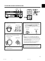
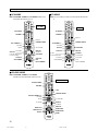
CONTROLS AND THEIR FUNCTIONS
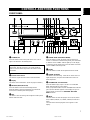
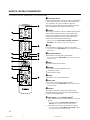
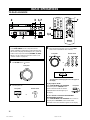
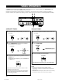
FRONT PANEL
1 STANDBY/ON
Press this switch to turn on the power to this unit. Press it
again to set this unit to the standby mode.
Standby mode
In this state, this unit consumes a very small quantity of
power to receive infrared-signals from the remote control
transmitter.
2 Remote control sensor
This receives signals from the remote control transmitter.
3 Display
This shows various information. (Refer to page 9 for details.)
4 MEMORY (MAN’L/AUTO FM)
Press this button to store the broadcasting stations.
When this button is pressed and held for more than three
seconds, the automatic preset tuning begins.
5 EDIT
This button is used to exchange the assignment of two preset
stations with each other.
6 TUNING MODE (AUTO/MAN’L MONO)
Press this button to switch the tuning mode to automatic or
manual. To select the automatic tuning mode, press this button
so that the “AUTO TUNING” indicator lights up on the display.
To select the manual tuning mode, press this button so that the
“AUTO TUNING” indicator goes off.
7 FM/AM
Press this button to switch the reception band to FM or AM.
8 TUNING UP/DOWN
This button is used for tuning. Press the UP side to tune in to
higher frequencies, and press the DOWN side to tune in to
lower frequencies.
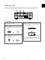
9 TAPE/MD MON / EXT. DECODER
Press this button to play a tape or an MD. The “TAPE/MD
MON” indicator lights up on the display.
When you press the button next, the “TAPE/MD MON” indicator
goes off, “EXT. DECDR” appears on the display and you can
play the signal connected to the EXTERNAL DECODER
INPUT terminals.
0 INPUT
Turn this selector to select the program source (VCR, VIDEO
AUX, TV/DBS, DVD/LD, CD, TUNER, PHONO) to listen to or
watch.
The name of the selected program source appears on the
display.
01RX-V495RDS-1 6/22/99, 12:26 PM7

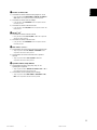
8
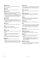
q INPUT MODE
This button switches the DVD/LD and TV/DBS input signal
mode (AUTO/ANALOG).
w VOLUME
This control is used to raise or lower the volume level.
e PHONES jack
When you use headphones, connect the headphones to the
PHONES jack. You can listen to the sound to be output from
the main speakers through the headphones.
When using headphones only, set both SPEAKERS A and B to
the OFF position and switch off the digital sound field processor
(so that no DSP program name appears on the display) by
pressing EFFECT.
r SPEAKERS
Set A or B (or both A and B) to the ON position for the main
speaker system (connected to this unit) that you want to use.
Set the button(s) for the main speaker system you don’t want to
use to the OFF position.
t A/B/C/D/E
Press this button to select one of a group (A to E) of preset
stations.
y Preset station number selector
Each of these buttons selects a preset station number
(1 to 8).
u Tone controls
These controls are only effective for the sound from the main
speakers.
BASS
Use this control to increase or decrease the low-frequency
response. The “0” position produces flat response.
TREBLE
Use this control to increase or decrease the high-frequency
response. The “0” position produces flat response.
i BALANCE
This control is only effective for the sound from the main
speakers.
Turn the control to adjust the balance of the output volume to
the left and right speakers to compensate for sound imbalance
caused by the speaker location or listening room conditions.
o RDS MODE
When an RDS station is received, pressing this button changes
the display into the PS mode, PTY mode, RT mode and/or CT
mode (if the station employs those RDS data services) in turn.
p PTY SEEK MODE
When this button is pressed, the unit is set in the PTY SEEK
mode.
a PTY SEEK START
Press this button to begin searching for a station after the
desired program type has been selected in the PTY SEEK
mode.
s EON
Press this button to select the desired program type (NEWS,
INFO, AFFAIRS, SPORT) when you want to call a radio
program of that type automatically.
d TIME/LEVEL
Press this button to select the item in the TIME/LEVEL mode.
f +/–
These buttons are used to adjust the settings of the SET MENU
mode and the TIME/LEVEL mode. In the TIME/LEVEL mode,
press + to increase the delay time or speaker output level.
Press – to decrease the delay time or speaker output level.
g SET MENU
Press this button to select functions in the SET MENU mode.
h PROGRAM selector
Press
or to select the DSP program.
The name of the selected program appears on the display.
j EFFECT
This button switches on and off the output from the center and
rear speakers so that the sound becomes the normal
2-channel.
* Even if the output from the center and rear speakers is off,
when the Dolby Digital is decoded, the signals on all
channels are distributed to the main channels and output
from the main speakers.
k VIDEO AUX terminals
Connect an auxiliary video or audio input source unit such as a
camcorder to these terminals. The source connected to these
terminals can be selected by INPUT.
01RX-V495RDS-1 6/22/99, 12:26 PM8

9
English
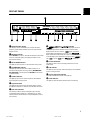
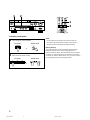
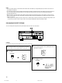
1 Multi-information display
This displays various information, for example the station
frequency, preset station number and name of the selected
program source.
2 MEMORY indicator
When MEMORY is pressed, this indicator flashes for about five
seconds. During this period, the displayed station can be
stored in the memory.
3 AUTO TUNING indicator
This lights up when the unit is in the automatic tuning mode.
4 TAPE/MD MON indicator
This lights up when the tape deck (or MD recorder, etc.) is
selected as the program source by pressing TAPE/MD MON /
EXT. DECODER on the front panel or TAPE/MD on the remote
control transmitter.
5 STEREO indicator
This lights up when an FM stereo broadcast with sufficient
signal strength is being received.
6 Signal-level meter
This indicates the signal level of the station being received.
If multipath interference is detected, the indication decreases.
7 RDS mode indicators
The name(s) of RDS mode(s) employed by the currently
received RDS station light(s) up. Illumination of one of the
named indicators shows that the corresponding RDS mode is
now selected.
DISPLAY PANEL
8
, and indicators
“
” lights up when the built-in Dolby Digital decoder is
on and the signal of the selected source encoded in Dolby
Digital sound is not in 2-channel. “
” lights up when the
built-in digital sound field processor is on, and “
”
lights up when the built-in Dolby Pro Logic Surround decoder is
on. Depending on the selected DSP program, both “
”
and “
”, or both “ ” and “ ” will light up.
9 PTY HOLD indicator
This lights up while a search is being performed in the PTY
SEEK mode.
0 EON indicator
This lights up when an RDS station that employs the EON data
service is being received.
q Program type name indicators
The name selected in the EON mode lights up.
w SLEEP indicator
This lights up while the built-in SLEEP timer is functioning.
01RX-V495RDS-1 6/22/99, 12:26 PM9

10
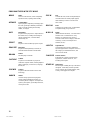
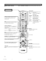
REMOTE CONTROL TRANSMITTER
See “REMOTE CONTROL TRANSMITTER” on page 49 for full details.
1 Component selector
Press the button for the component you want to control with the
remote control transmitter. (The proper code must be set for
your component. See “SETUP CODES” on page 56.)
When the component selector has been pressed, the remote
control transmitter is set to operate that component.
2 POWER
When you have preset the code for a YAMAHA component, this
button switches between the power on and standby mode.
When you have preset the code for another manufacturer’s
component, this button turns on that component if it has a
remote control transmitter with a power button.
* It only functions when AMP<TUNER>, TAPE/MD, CD, DVD/LD or
DVD MENU on the component selector has been pressed.
3 TEST
Press this button to output the test tone for each speaker.
* It only functions when AMP<TUNER> on the component selector has
been pressed.
4 A/B/C/D/E, PRESET +/–
These buttons are used to select a preset station.
* They only function when AMP<TUNER> on the component selector
has been pressed.
5 MUTE
Press this button to mute the sound.
6 VOLUME
These buttons are used to adjust the volume.
: Turns up the volume.
: Turns down the volume.
7 SLEEP
This button is used to set the SLEEP timer.
8 PRG+, PRG–
These buttons are used to select a DSP program.
* They only function when AMP<TUNER> on the component selector
has been pressed.
9 Indicator
This flashes in red when a button on the remote control
transmitter is pressed. When it flashes rapidly several times,
press the selected button again.
0 Input selector (1 to 9)
1)
/Numeric buttons
2)
1) These buttons are used to select the program source to be
played.
* They only function when AMP<TUNER>, TAPE/MD, CD or
DVD/LD on the component selector has been pressed.
2) These buttons are used to select the menu or channel.
* They only function when DVD MENU, VCR, CBL/DBS or TV on
the component selector has been pressed.
01RX-V495RDS-1 6/22/99, 12:26 PM10

11
English
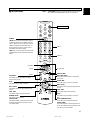
q EFFECT
1)
/CLEAR
2)
/+100
3)
1) This button is used to switch the DSP program on or off.
* It only functions when AMP<TUNER>, TAPE/MD, CD, DVD/LD,
VCR or TV on the component selector has been pressed.
2) This button is used to clear the settings.
* It only functions when DVD MENU on the component selector
has been pressed.
3) This button is used to select the channel.
* It only functions when CBL/DBS on the component selector has
been pressed.
w ENTER
1)
/+10
2)
1) This button is used to enter the channel.
* It only functions when VCR, CBL/DBS or TV on the component
selector has been pressed.
2) This button is used to select the menu.
* It only functions when DVD MENU on the component selector
has been pressed.
e DISC SKIP +/–
1)
/CH +/–
2)
1) These buttons are used to skip to the next or previous disc.
* They only function when CD, DVD/LD or DVD MENU on the
component selector has been pressed.
2) These buttons are used to select the next or previous
channel.
* They only function when VCR, CBL/DBS or TV on the
component selector has been pressed.
r Operation buttons
1)
/Setup buttons
2)
1) These buttons function as play, stop, skip, etc. for
operating the component.
* They only function when TAPE/MD, CD, DVD/LD, VCR or TV on
the component selector has been pressed.
2) These buttons are for adjusting various settings.
* They only function when AMP<TUNER>, DVD MENU or CBL/
DBS on the component selector has been pressed.
01RX-V495RDS-1 6/22/99, 12:26 PM11

12
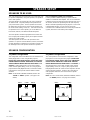
SPEAKER SETUP
This unit is designed to provide the best sound-field quality with
a 5-speaker configuration, using main speakers, rear speakers
and a center speaker.
The main speakers are used for the main source sound plus
the effect sounds. They will probably be the speakers from
your present stereo system. The rear speakers are used for
the effect and surround sounds, and the center speaker is for
the center sounds (dialog, vocals, etc.). If for some reason it is
not practical to use a center speaker, you can do without it.
Best results, however, are obtained with the full system.
The main speakers should be high-performance models and
have enough power-handling capacity to accept the maximum
output of your audio system.
The other speakers do not have to be equal to the main
speakers. For precise sound localization, however, it is ideal to
use high-performance models that can reproduce sounds over
the full-range for the center speaker and the rear speakers.
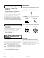
5-Speaker Configuration
This configuration is the most effective and recommended one.
When playing back a source using the DSP program,
DOLBY PRO LOGIC/DOLBY DIGITAL, DOLBY PRO LOGIC
ENHANCED/DOLBY DIGITAL ENHANCED, 70 mm MOVIE
THEATER/DIGITAL MOVIE THEATER, MONO MOVIE or TV
SPORTS, or when playing back a source which contains
center-channel signals (dialog, vocals, etc.) using any DSP
program that is Dolby Digital-decoded, conversations will be
output from the center speaker and the ambience will be
excellent.
Note: Set the CNTR (CENTER SPEAKER) mode to the
“LARGE” or “SMALL” position. (See page 21 for
details.)
SPEAKER CONFIGURATION
Use of a subwoofer expands your sound field
It is also possible to further expand your system with the
addition of a subwoofer and amplifier. The use of a subwoofer
is effective not only for reinforcing bass frequencies from any or
all channels, but also for reproducing the LFE (low frequency
effect) sound with high fidelity when playing back a source that
is Dolby Digital-decoded. You may wish to choose the
convenience of a YAMAHA Active Servo Processing Subwoofer
System, which has its own built-in power amplifier.
4-Speaker Configuration
The center speaker is not used in this configuration. When
playing back a source using the DSP program, DOLBY PRO
LOGIC/DOLBY DIGITAL, DOLBY PRO LOGIC ENHANCED/
DOLBY DIGITAL ENHANCED, 70 mm MOVIE THEATER/
DIGITAL MOVIE THEATER, MONO MOVIE or TV SPORTS, or
when playing back a source which contains center-channel
signals (dialog, vocals, etc.) using any DSP program that is
Dolby Digital-decoded, the center sound is output from the left
and the right main speakers. However, the sound effect of
other programs will be the same as that of the 5-speaker
configuration.
Note: Be sure to set the CNTR (CENTER SPEAKER) mode to
the “NONE” position. (See page 21 for details.)
SPEAKERS TO BE USED
Main L Center Main R
Rear L Rear R
Dialog
Surround sound
Main L Main R
Rear L Rear R
Dialog
Surround sound
01RX-V495RDS-2 6/22/99, 12:26 PM12

13
English
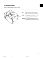
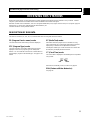
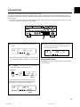
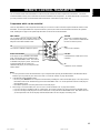
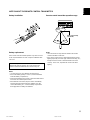
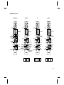
SPEAKER PLACEMENT
Refer to the following diagram when you place the speakers.
Main: The position of your present stereo speaker
system.
Rear: Behind your listening position, facing slightly
inward. Nearly 1.8 m (approx. 6 feet) up from the
floor.
Center: Precisely between the main speakers. (To avoid
interference with TV sets, use a magnetically
shielded speaker.)
Subwoofer: The position of the subwoofer is not as critical,
because low bass tones are not highly directional.
Rear
speaker (R)
Main
speaker (R)
Center speaker
Subwoofer
Main
speaker (L)
Rear
speaker
(L)
01RX-V495RDS-2 6/22/99, 12:26 PM13

14
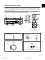
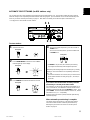
SWITCHED AC OUTLET(S)
Europe model..................................... 2 SWITCHED OUTLETS
U.K. model ............................................1 SWITCHED OUTLET
Use these to connect the power cords from your components to
this unit.
The power to the SWITCHED AC OUTLET(S) is controlled by
this unit’s STANDBY/ON or the provided remote control
transmitter’s POWER. These outlets will supply power to any
component whenever this unit is turned on.
The maximum power (total power consumption of components)
that can be connected to the SWITCHED AC OUTLET(S) is
100 watts.
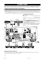
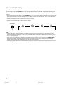
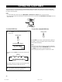
CONNECTIONS
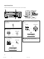
Never plug in this unit and other components until all connections have been completed.
CONNECTIONS WITH OTHER COMPONENTS
When making connections between this unit and other components, be sure all connections are made correctly, that is to say L
(left) to L, R (right) to R, “+” to “+” and “–” to “–”. Also, refer to the owner’s manual for each component to be connected to this unit.
* If you have YAMAHA components numbered as !, #, $, etc. on the rear panel, connections can be made easily by making sure
to connect the output (or input) terminals of each component to the same-numbered terminals of this unit.
Turntable Monitor TV
DVD player,
LD player, etc.
CD player Tape deck,
MD recorder, etc.
TV/DBS tuner
VCR
(Video cassette recorder)
To AC outlet
(Europe model)
GND terminal (for turntable use)
Connecting the ground (earth) wire of the turntable to the GND terminal will normally minimize hum, but in some cases, better
results may be obtained with the ground wire disconnected.
01RX-V495RDS-2 6/22/99, 12:26 PM14

15
English
R
L
R
L
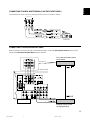
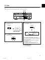
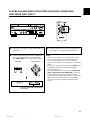
CONNECTING TO AN EXTERNAL DECODER
When using the DTS or other decoder with 6-channel discrete outputs, connect the 6CH DISCRETE OUTPUT terminals of the
decoder to the EXTERNAL DECODER INPUT terminals of this unit.
DTS or other decoder with 6-channel
discrete outputs
DVD player, LD player or other
unit with digital outputs
(Europe model)
Camcorder
CONNECTING TO VIDEO AUX TERMINALS (ON THE FRONT PANEL)
These terminals are used to connect any video input source, such as a camcorder, to this unit.
VIDEO AUX
01RX-V495RDS-2 6/22/99, 12:26 PM15

16
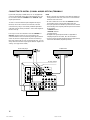
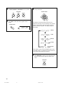
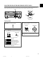
CONNECTING TO DIGITAL (COAXIAL AND/OR OPTICAL) TERMINALS
If your DVD (LD) player, TV/DBS tuner, etc. are equipped with
coaxial or optical digital audio signal output terminals, they can
be connected to this unit’s COAXIAL and/or OPTICAL digital
signal input terminals.
To make a connection between optical digital audio signal
terminals, remove the cover from each terminal, and then
connect them by using a commercially available optical fiber
cable that conforms to EIAJ standards. Other cables might not
function correctly.
Even if you connect an audio/video unit to the COAXIAL (or
OPTICAL) terminal of this unit, you must keep the unit
connected with the same named analog audio signal terminals
of this unit, because a digital signal cannot be recorded by a
tape deck, MD recorder or VCR connected to this unit. You can
easily switch the selection of input signals between “digital” and
“analog”. (See page 28 for details.)
Notes
• When connecting an audio/video unit to both the digital and
analog terminals of this unit, make sure to connect between
terminals of the same name.
• Be sure to attach the covers when the OPTICAL terminals
are not being used in order to protect them from dust.
• The input signal from the DVD/LD input terminals is selected
in the following order of priority with the input mode set to the
AUTO position:
1 COAXIAL terminal
2 OPTICAL terminal
3 Analog terminal
• All digital audio signal input terminals are applicable to
sampling frequencies of 32 kHz, 44.1 kHz and 48 kHz.
• If your LD player has Dolby Digital RF signal output terminal,
use the RF demodulator (separate purchase).
DVD or LD player TV/DBS tuner
(Europe model)
01RX-V495RDS-2 6/22/99, 12:26 PM16

17
English
Note
Use speakers with the specified impedance shown on the
rear panel of this unit.
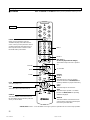
Main speaker connections
One or two speaker systems can be connected to this unit. If
you use only one speaker system, connect it to either of the
SPEAKERS A or B terminals.
Rear speaker connections
A rear speaker system can be connected to this unit. Place
them to the rear of your listening position.
Center speaker connection
A center speaker can be connected to this unit. Place it on or
under the TV.
Subwoofer connection
You may wish to add a subwoofer to reinforce low frequencies
or to output low bass sound from the subwoofer channel.
If you have a subwoofer with built-in amplifier, including the
YAMAHA Active Servo Processing Subwoofer System, connect
the SUBWOOFER OUTPUT terminal of this unit to the input
terminal of the subwoofer system.
If you have a separate amplifier and subwoofer, connect the
SUBWOOFER OUTPUT terminal of this unit to the input
terminal of the subwoofer amplifier, and then connect the
speaker terminals of the subwoofer amplifier to the subwoofer.
When the input signals to this unit are for normal 2-channel
stereo, this terminal outputs only frequencies below 90 Hz from
the main and center channels. When discrete signals are input
to this unit and are selected as the input source, this terminal
outputs signals from the subwoofer channel.
Note: The output level of signals from this terminal is adjusted
by VOLUME on the front panel or VOLUME (
) on
the remote control transmitter.
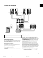
CONNECTING SPEAKERS
Rear speakers
Subwoofer system
Center speaker
Right
Left
Main speakers A Main speakers B
Right
Left
Right Left
R
L
REAR
(SURROUND)
CENTER
MAIN
SUB
WOOFER
R
L
OUTPUT
SPEAKERS
01RX-V495RDS-2 6/22/99, 12:26 PM17

18
How to connect
Connect the SPEAKERS terminals to your speakers with wire of the proper gauge, cut as short as possible. If the connections are
faulty, no sound will be heard from the speakers. Make sure that the polarity of the speaker wires is correct, that is the + and –
markings are observed. If these wires are reversed, the sound will be unnatural and lack bass.
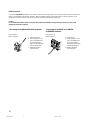
Caution
Do not let the bare speaker wires touch each other and do not let them touch any metal part of this unit. This could
damage the unit and/or speakers.
Connecting to the MAIN SPEAKERS terminals
Red: positive (+)
Black: negative (–)
1 Unscrew the knob.
2 Remove approx. 5 mm
(1/4”) of insulation from
each of the speaker
wires and insert the bare
wire into the terminal.
3 Tighten the knob to
secure the wire.
1 Press the tab.
2 Remove approx. 5 mm
(1/4”) of insulation from
each of the speaker
wires and insert the bare
wire into the terminal.
3 Release the tab to
secure the wire.
Connecting to the REAR and CENTER
SPEAKERS terminals
Red: positive (+)
Black: negative (–)
1
2
3
2
3
1
01RX-V495RDS-2 6/22/99, 12:26 PM18

19
English
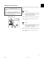
IMPEDANCE SELECTOR SWITCH
Select the position whose requirements your speaker system
meets.
(Upper position)
Main: If you use one pair of main speakers, the impedance of
each speaker must be 4 Ω or higher.
If you use two pairs of main speakers, the impedance
of each speaker must be 8 Ω or higher.
Center: The impedance of the speaker must be 6 Ω or higher.
Rear: The impedance of each speaker must be 6 Ω or
higher.
(Lower position)
Main: If you use one pair of main speakers, the impedance of
each speaker must be 8 Ω or higher.
If you use two pairs of main speakers, the impedance
of each speaker must be 16 Ω or higher.
Center: The impedance of the speaker must be 8 Ω or higher.
Rear: The impedance of each speaker must be 8 Ω or
higher.
WARNING
Do not change the IMPEDANCE SELECTOR switch setting
while the power to this unit is on, otherwise this unit may be
damaged.
If this unit fails to turn on when the STANDBY/ON switch is
pressed, the IMPEDANCE SELECTOR switch may not be
fully set to either end. If so, set the switch to either end fully
when this unit is in the standby mode.
IMPEDANCE SELECTOR
(Europe model)
01RX-V495RDS-2 6/22/99, 12:26 PM19

20
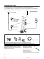
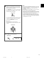
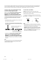
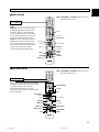
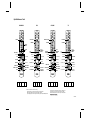
Connecting the AM loop antenna
* The AM loop antenna should be placed away from this unit. The antenna may be hung on a wall.
* The AM loop antenna always should be connected, even if an outdoor AM antenna is connected to this unit.
ANTENNA CONNECTIONS
Each antenna should be correctly connected to the designated terminals, referring to the following diagram.
Both AM and FM indoor antennas are included with this unit. In general, these antennas will probably provide sufficient signal
strength. Nevertheless, a properly installed outdoor antenna will give clearer reception than an indoor one. If you experience poor
reception quality, an outdoor antenna may result in improvement.
GND TERMINAL
For maximum safety and minimum interference, connect the
GND terminal to a good earth ground. A good earth ground is a
metal stake driven into moist earth.
Notes
• When connecting the indoor FM
antenna, firmly insert its connector
into the FM ANT terminal.
• If you need an outdoor FM antenna to
improve FM reception quality, either
300-ohm feeder or coaxial
cable may be used. In locations
troubled by electrical interference, coaxial cable is preferable.
Orient so that the best
reception is obtained.
12 3
Outdoor FM antenna
75-ohm/300-ohm
antenna adapter
75-ohm coaxial cable
75-ohm/300-ohm
antenna adapter
300-ohm feeder
Ground
AM loop
antenna
(included)
Outdoor AM antenna
Indoor FM
antenna
(included)
1
2
3
01RX-V495RDS-2 6/22/99, 12:26 PM20
Sayfa yükleniyor...
Sayfa yükleniyor...
Sayfa yükleniyor...
Sayfa yükleniyor...
Sayfa yükleniyor...
Sayfa yükleniyor...
Sayfa yükleniyor...
Sayfa yükleniyor...
Sayfa yükleniyor...
Sayfa yükleniyor...
Sayfa yükleniyor...
Sayfa yükleniyor...
Sayfa yükleniyor...
Sayfa yükleniyor...
Sayfa yükleniyor...
Sayfa yükleniyor...
Sayfa yükleniyor...
Sayfa yükleniyor...
Sayfa yükleniyor...
Sayfa yükleniyor...
Sayfa yükleniyor...
Sayfa yükleniyor...
Sayfa yükleniyor...
Sayfa yükleniyor...
Sayfa yükleniyor...
Sayfa yükleniyor...
Sayfa yükleniyor...
Sayfa yükleniyor...
Sayfa yükleniyor...
Sayfa yükleniyor...
Sayfa yükleniyor...
Sayfa yükleniyor...
Sayfa yükleniyor...
Sayfa yükleniyor...
Sayfa yükleniyor...
Sayfa yükleniyor...
Sayfa yükleniyor...
Sayfa yükleniyor...
Sayfa yükleniyor...
Sayfa yükleniyor...
Sayfa yükleniyor...
Sayfa yükleniyor...
Sayfa yükleniyor...
Sayfa yükleniyor...
Sayfa yükleniyor...
Sayfa yükleniyor...
Sayfa yükleniyor...
Sayfa yükleniyor...
-
 1
1
-
 2
2
-
 3
3
-
 4
4
-
 5
5
-
 6
6
-
 7
7
-
 8
8
-
 9
9
-
 10
10
-
 11
11
-
 12
12
-
 13
13
-
 14
14
-
 15
15
-
 16
16
-
 17
17
-
 18
18
-
 19
19
-
 20
20
-
 21
21
-
 22
22
-
 23
23
-
 24
24
-
 25
25
-
 26
26
-
 27
27
-
 28
28
-
 29
29
-
 30
30
-
 31
31
-
 32
32
-
 33
33
-
 34
34
-
 35
35
-
 36
36
-
 37
37
-
 38
38
-
 39
39
-
 40
40
-
 41
41
-
 42
42
-
 43
43
-
 44
44
-
 45
45
-
 46
46
-
 47
47
-
 48
48
-
 49
49
-
 50
50
-
 51
51
-
 52
52
-
 53
53
-
 54
54
-
 55
55
-
 56
56
-
 57
57
-
 58
58
-
 59
59
-
 60
60
-
 61
61
-
 62
62
-
 63
63
-
 64
64
-
 65
65
-
 66
66
-
 67
67
-
 68
68


Yamaha HTR-5140RDS Kullanım kılavuzu
- Kategori
- Alıcı
- Tip
- Kullanım kılavuzu
diğer dillerde
- español: Yamaha HTR-5140RDS Manual de usuario
- français: Yamaha HTR-5140RDS Manuel utilisateur
- italiano: Yamaha HTR-5140RDS Manuale utente
- svenska: Yamaha HTR-5140RDS Användarmanual
- čeština: Yamaha HTR-5140RDS Uživatelský manuál
- polski: Yamaha HTR-5140RDS Instrukcja obsługi
- Deutsch: Yamaha HTR-5140RDS Benutzerhandbuch
- português: Yamaha HTR-5140RDS Manual do usuário
- English: Yamaha HTR-5140RDS User manual
- dansk: Yamaha HTR-5140RDS Brugermanual
- русский: Yamaha HTR-5140RDS Руководство пользователя
- Nederlands: Yamaha HTR-5140RDS Handleiding
- română: Yamaha HTR-5140RDS Manual de utilizare
İlgili makaleler
-
Yamaha RX-V495RDS Kullanım kılavuzu
-
-
-
-
Yamaha HTR-5150 El kitabı
-
-
-
-
-