
Home Theater Package
(Subwoofer Integrated Receiver + Speaker)
YHT-S400
(SR-300 + NS-BR300)
Owner’s Manual
English

2 En
1 Read these instructions.
2 Keep these instructions.
3 Heed all warnings.
4 Follow all instructions.
5 Do not use this apparatus near water.
6 Clean only with dry cloth.
7 Do not block any ventilation openings. Install in
accordance with the manufacturer’s instructions.
8 Do not install near any heat sources such as radiators,
heat registers, stoves, or other apparatus (including
amplifiers) that produce heat.
9 Do not defeat the safety purpose of the polarized or
grounding-type plug. A polarized plug has two blades
with one wider than the other. A grounding type plug
has two blades and a third grounding prong. The wide
blade or the third prong are provided for your safety. If
the provided plug does not fit into your outlet, consult
an electrician for replacement of the obsolete outlet.
10 Protect the power cord from being walked on or pinched
particularly at plugs, convenience receptacles, and the
point where they exit from the apparatus.
11 Only use attachments/accessories specified by the
manufacturer.
12 Use only with the cart, stand, tripod,
bracket, or table specified by the
manufacturer, or sold with the apparatus.
When a cart is used, use caution when
moving the cart/apparatus combination to
avoid injury from tip-over.
13 Unplug this apparatus during lightning storms or when
unused for long periods of time.
14 Refer all servicing to qualified service personnel.
Servicing is required when the apparatus has been
damaged in any way, such as power-supply cord or plug
is damaged, liquid has been spilled or objects have
fallen into the apparatus, the apparatus has been exposed
to rain or moisture, does not operate normally, or has
been dropped.
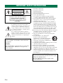
IMPORTANT SAFETY INSTRUCTIONS
CAUTION
RISK OF ELECTRIC
SHOCK DO NOT OPEN
CAUTION: TO REDUCE THE RISK OF
ELECTRIC SHOCK, DO NOT REMOVE
COVER (OR BACK). NO USER-
SERVICEABLE PARTS INSIDE. REFER
SERVICING TO QUALIFIED SERVICE
PERSONNEL.
• Explanation of Graphical Symbols
The lightning flash with arrowhead symbol,
within an equilateral triangle, is intended to alert
you to the presence of uninsulated “dangerous
voltage” within the product’s enclosure that may
be of sufficient magnitude to constitute a risk of
electric shock to persons.
The exclamation point within an equilateral
triangle is intended to alert you to the presence of
important operating and maintenance (servicing)
instructions in the literature accompanying the
appliance.
IMPORTANT
Please record the serial number of this unit in the
space below.
MODEL:
Serial No.:
The serial number is located on the rear of the unit.
Retain this Owner’s Manual in a safe place for
future reference.
FOR CANADIAN CUSTOMERS
To prevent electric shock, match wide blade of plug
to wide slot and fully insert.
This Class B digital apparatus complies with
Canadian ICES-003.

3 En
Yamaha and the Electronic Industries Association’s Consumer Electronics Group want you to get the most out
of your equipment by playing it at a safe level. One that lets the sound come through loud and clear without
annoying blaring or distortion – and, most importantly, without affecting your sensitive hearing. Since hearing
damage from loud sounds is often undetectable until it is too late, Yamaha and the Electronic Industries
Association’s Consumer Electronics Group recommend you to avoid prolonged exposure from excessive
volume levels.
FCC INFORMATION (for US customers)
1 IMPORTANT NOTICE: DO NOT MODIFY
THIS UNIT!
This product, when installed as indicated in the
instructions contained in this manual, meets FCC
requirements. Modifications not expressly approved
by Yamaha may void your authority, granted by the
FCC, to use the product.
2 IMPORTANT: When connecting this product to
accessories and/or another product use only high
quality shielded cables. Cable/s supplied with this
product MUST be used. Follow all installation
instructions. Failure to follow instructions could void
your FCC authorization to use this product in the
USA.
3 NOTE: This product has been tested and found to
comply with the requirements listed in FCC
Regulations, Part 15 for Class “B” digital devices.
Compliance with these requirements provides a
reasonable level of assurance that your use of this
product in a residential environment will not result in
harmful interference with other electronic devices.
This equipment generates/uses radio frequencies and,
if not installed and used according to the instructions
found in the users manual, may cause interference
harmful to the operation of other electronic devices.
Compliance with FCC regulations does not guarantee
that interference will not occur in all installations. If
this product is found to be the source of interference,
which can be determined by turning the unit “OFF”
and “ON”, please try to eliminate the problem by
using one of the following measures:
Relocate either this product or the device that is being
affected by the interference.
Utilize power outlets that are on different branch
(circuit breaker or fuse) circuits or install AC line
filter/s.
In the case of radio or TV interference, relocate/
reorient the antenna. If the antenna lead-in is 300 ohm
ribbon lead, change the lead-in to coaxial type cable.
If these corrective measures do not produce
satisfactory results, please contact the local retailer
authorized to distribute this type of product. If you can
not locate the appropriate retailer, please contact
Yamaha Electronics Corp., U.S.A. 6660 Orangethorpe
Ave., Buena Park, CA 90620.
The above statements apply ONLY to those products
distributed by Yamaha Corporation of America or its
subsidiaries.
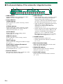
We Want You Listening For A Lifetime

4 En
1 To assure the finest performance, please read this
manual carefully. Keep it in a safe place for future
reference.
2 Install this unit in a well ventilated, cool, dry, clean
place - away from direct sunlight, heat sources,
vibration, dust, moisture, and/or cold. For proper
ventilation, allow the following minimum clearances.
Top: 5 cm (2 in)
Rear: 5 cm (2 in)
Sides: 5 cm (2 in)
3 Locate this unit away from other electrical appliances,
motors, or transformers to avoid humming sounds.
4 Do not expose this unit to sudden temperature changes
from cold to hot, and do not locate this unit in an
environment with high humidity (i.e. a room with a
humidifier) to prevent condensation inside this unit,
which may cause an electrical shock, fire, damage to
this unit, and/or personal injury.
5 Avoid installing this unit where foreign objects may fall
onto this unit and/or this unit may be exposed to liquid
dripping or splashing. On the top of this unit, do not
place:
– Other components, as they may cause damage and/or discoloration
on the surface of this unit.
– Burning objects (i.e. candles), as they may cause fire, damage to
this unit, and/or personal injury.
– Containers with liquid in them, as they may fall and liquid may
cause electrical shock to the user and/or damage to this unit.
6 Do not cover this unit with a newspaper, tablecloth,
curtain, etc. in order not to obstruct heat radiation. If the
temperature inside this unit rises, it may cause fire,
damage to this unit, and/or personal injury.
7 Do not plug in this unit to a wall outlet until all
connections are complete.
8 Do not operate this unit upside-down. It may overheat,
possibly causing damage.
9 Do not use force on switches, knobs and/or cords.
10 When disconnecting the power cable from the wall
outlet, grasp the plug; do not pull the cable.
11 Do not clean this unit with chemical solvents; this might
damage the finish. Use a clean, dry cloth.
12 Only voltage specified on this unit must be used. Using
this unit with a higher voltage than specified is
dangerous and may cause fire, damage to this unit, and/
or personal injury. Yamaha will not be held responsible
for any damage resulting from use of this unit with a
voltage other than specified.
13 To prevent damage by lightning, keep the power cable
and outdoor antennas disconnected from a wall outlet or
the unit during a lightning storm.
14 Do not attempt to modify or fix this unit. Contact
qualified Yamaha service personnel when any service is
needed. The cabinet should never be opened for any
reasons.
15 When not planning to use this unit for long periods of
time (i.e. vacation), disconnect the AC power plug from
the wall outlet.
16 Be sure to read the “Troubleshooting” section on
common operating errors before concluding that this
unit is faulty.
17 Before moving this unit, press to set this unit in
standby mode, and disconnect the power supply cable
from the wall outlet.
18 Condensation will form when the surrounding
temperature changes suddenly. Disconnect the power
supply cable from the outlet, then leave the unit alone.
19 Install this unit near the wall outlet and where the AC
power plug can be reached easily.
20 The batteries shall not be exposed to excessive heat such
as sunshine, fire or like.
21 Secure placement or installation is the owner’s
responsibility. Yamaha shall not be liable for any
accident caused by improper placement or installation of
speakers.
■ For U.K. customers
If the socket outlets in the home are not suitable for
the plug supplied with this appliance, it should be cut
off and an appropriate 3 pin plug fitted. For details,
refer to the instructions described below.
The plug severed from the mains lead must be destroyed, as
a plug with bared flexible cord is hazardous if engaged in a
live socket outlet.
■ Special Instructions for U.K. Model
Caution: Read this before operating your unit.
WARNING
TO REDUCE THE RISK OF FIRE OR ELECTRIC
SHOCK, DO NOT EXPOSE THIS UNIT TO RAIN
OR MOISTURE.
As long as this unit is connected to the AC wall
outlet, it is not disconnected from the AC power
source even if you turn off this unit by . In this
state, this unit is designed to consume a very small
quantity of power.
Note
IMPORTANT
THE WIRES IN THE MAINS LEAD ARE
COLOURED IN ACCORDANCE WITH THE
FOLLOWING CODE:
Blue: NEUTRAL
Brown: LIVE
As the colours of the wires in the mains lead of this
apparatus may not correspond with the coloured
markings identifying the terminals in your plug,
proceed as follows:
The wire which is coloured BLUE must be
connected to the terminal which is marked with the
letter N or coloured BLACK. The wire which is
coloured BROWN must be connected to the
terminal which is marked with the letter L or
coloured RED.
Making sure that neither core is connected to the
earth terminal of the three pin plug.

INTRODUCTION PREPARATION
BASIC
OPERATION
USEFUL
OPERATION
ADDITIONAL
INFORMATION
5 En
INTRODUCTION
Getting started....................................................6
Supplied parts........................................................ 6
Controls and functions ..........................................7
PREPARATION
Placing ...............................................................10
Placing the speaker ............................................. 10
Connection ........................................................12
Overview............................................................. 12
Connecting a TV ................................................. 13
Connecting Blu-ray disc player or
set-top box ....................................................... 13
BASIC OPERATION
Basic playback operation.................................14
Enjoying sound modes .....................................15
Surround mode.................................................... 15
Stereo mode ........................................................ 15
UniVolume™...................................................... 15
Listening to FM broadcasts.............................16
Basic tuning operation ........................................ 16
Editing the preset FM station .............................. 16
Using optional equipment................................18
Connecting dock ................................................. 18
Using iPod™....................................................... 18
Using Bluetooth™ components .......................... 19
USEFUL OPERATION
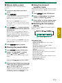
Setup menu ....................................................... 20
Overview .............................................................20
Basic procedure...................................................20
Adjusting the volume balance during
playback...........................................................21
Adjusting high/low frequency sound
(tone control)....................................................21
Adjusting the audio delay....................................21
Setting the audio output ......................................21
Switching on/off the HDMI™ control
function ............................................................21
Changing the brightness of the front panel
display..............................................................22
Changing the setting of the speaker type ............22
Setting the distance between the speakers ..........22
Using the HDMI™ control function ...................23
ADDITIONAL INFORMATION
Additional information.................................... 24
Troubleshooting ..................................................24
Glossary...............................................................27
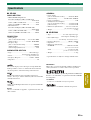
Specifications ......................................................29
Available signal information...............................30
Contents
■ About this manual
• In this manual, operations that can be performed using either the front panel buttons or the remote control are
explained using the remote control.
• y indicates a tip for your operation. Notes contain important information about safety and operating
instructions.
• This manual is produced prior to production. Design and specifications are subject to change in part as a result
of improvements, etc. In case of differences between the manual and the product, the product has priority.

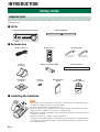
6 En
INTRODUCTION
This product consists of the following items. Before making connections, make sure you have received all of the
following items.
■ Units
■ Accessories
■ Installing the batteries
Getting started
Supplied parts
Subwoofer Integrated Receiver (SR-300) Speaker (NS-BR300)
Speaker cable (3 m) Remote control Indoor FM antenna
(U.S.A., Canada and
Asia models)
(Europe, Russia and
Australia models)
Stand × 2
(for speaker)
Battery × 2 (AAA, R03, UM4) Mounting template
Non-skid pad
(4 pieces)
Screw × 2
(for stand)
CD-ROM
(Owner’s Manual)
Quick Reference
Guide
• If the effective operation distance of the remote control decreases considerably, replace
the batteries with two new ones as soon as possible.
• Do not use an old battery together with new one.
• Do not use different types of batteries (for example, alkaline and manganese) together.
Their performance will vary, even if they are similar in shape.
• If the batteries run out, immediately remove them from the remote control to prevent an
explosion or acid leak.
• Dispose of batteries according to regional regulations.
• If a battery starts leaking, dispose of it immediately. Be careful not to let leaking battery
acid come into contact with your skin or clothing. Before inserting new batteries, wipe
the compartment clean.
Notes

7 En
Getting started
INTRODUCTION
■ Front panel of the subwoofer integrated receiver
1
Turns on the system, or sets it to standby mode.
(☞ P. 14)
A small amount of electricity is consumed to receive
the infrared signal from the remote control even when
the system is in standby mode.
2 STATUS indicator
Lights up to show the system condition. (☞ P. 14)
3 INPUT
Selects an input source you want to listen to.
(☞ P. 14)
4 VOLUME –/+
Controls the volume of the system. (☞ P. 14)
5 Remote control sensor
Receives infrared signals from the remote control.
(☞ P. 9, 12)
6 Front panel display
Shows information about the operational status of
the system. (☞ P. 14)
■ Rear panel of the subwoofer integrated receiver
1 Power Cable
For connecting an AC wall outlet. (☞ P. 12)
2 HDMI IN 1 - 3/HDMI OUT
• HDMI IN 1 - 3 for connecting HDMI
compatible external components. (☞ P. 13)
• HDMI OUT for connecting an HDMI
compatible TV. (☞ P. 13)
3 DIGITAL IN jack
For connecting optical digital cable to the TV.
(☞ P. 13)
4 ANALOG INPUT jack
For connecting analog audio cable to external
components. (☞ P. 12)
5 DOCK terminal
For connecting an optional Yamaha iPod universal
dock (such as YDS-11, sold separately) or
Bluetooth wireless audio receiver (such as YBA-
10, sold separately). (☞ P. 18)
6 ANTENNA terminal
For connecting supplied FM antenna. (☞ P. 12)
7 SPEAKERS terminal
For connecting speakers. (☞ P. 12)
Controls and functions
1 2 3 4 5 6
Note
1 2
7 6 5 4 3

Getting started
8 En
■ Front panel display of the subwoofer integrated receiver
1 HDMI indicator
Lights up during normal communication when
HDMI is selected as an input source.
2 Tuner indicators
TUNED indicator
Lights up when the system is receiving a station.
(☞ P. 16)
STEREO indicator
Lights up when the system is receiving a strong
signal from an FM stereo broadcast station in
automatic tuning mode. (☞ P. 16)
AUTO indicator
Flashes when the system is tuning station
automatically. (☞ P. 16)
MEMORY indicator
Flashes when the system is storing a station.
(☞ P. 16, 17)
EMPTY indicator
Lights up when the storing preset number is empty.
(☞ P. 17)
PS/PTY/RT/CT indicator (Europe and
Russia models only)
Lights up according to the available Radio Data
System information. (☞ P. 17)
3 Decoder indicators
The respective indicator lights up when any of the
decoders of the system is activated.
4 DOCK indicator
• Lights up when the system is receiving a signal
from an iPod stationed in the Yamaha iPod
universal dock (such as YDS-11, sold
separately) connected to the DOCK terminal of
the subwoofer integrated receiver. (☞ P. 18)
• Lights up while the Yamaha Bluetooth wireless
audio receiver (such as YBA-10, sold
separately) is connected to the Bluetooth
component. (☞ P. 19)
• Flashes while the connected Yamaha Bluetooth
wireless audio receiver (such as YBA-10, sold
separately) and the Bluetooth component are
pairing (☞ P. 19) or while the Yamaha
Bluetooth wireless audio receiver is searching
for the Bluetooth component. (☞ P. 19)
5 VOLUME indicator
• Indicates the current volume level.
• Flashes while the mute function is activated.
(☞ P. 14)
6 Multi information display
Shows the selected input source, current sound
mode and other information.
7 ENHANCER indicator
Lights up when compressed music enhancer
function is activated. (☞ P. 18)
8 UNIVOLUME indicator
Lights up when UniVolume mode is selected.
(☞ P. 15)
1 2 3 4
5
8
7
6

9 En
Getting started
INTRODUCTION
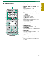
■ Remote control
1 Input buttons
Select an input source you want to listen to.
(☞ P. 14)
2 MEMORY, TUNING / , PRESET / ,
INFO
Control an FM tuner. (☞ P. 16)
3 OPTION
Enters OPTION menu when operating FM
function or using Bluetooth component. (☞ P. 16,
19)
4 (MENU) / ( ) / ( ) / ( ) /
(Center)
• Change the setting.
• Control an iPod. (☞ P. 18)
S / T: Control the wheel of iPod.
5 RETURN
Returns to the previous menu or cancels preset
registration/pairing operation.
6 SUBWOOFER (+/–)
Adjust the volume balance of subwoofer.
(☞ P. 21)
7 SURROUND MODE
Selects the surround mode. (☞ P. 15)
8 STEREO MODE
Turns extended stereo mode on and off alternately.
(☞ P. 15)
9 UNIVOLUME
Turns UniVolume mode on and off. (☞ P. 15)
0 VOLUME (+/–)/MUTE
Control the volume of the system. (☞ P. 14)
A SETUP
Enters the setup menu. (☞ P. 20)
B
Turns on the system, or sets it to standby mode.
(☞ P. 14)
1
B
A
@
9
8
2
3
4
5
6
7
Infrared signal
transmitter

10 En
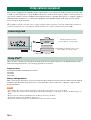
PREPARATION
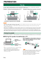
To enjoy quality sound thoroughly, place this system in the appropriate positions, and install the components
properly. The following illustrations are the setting images of this system.
Example 1: Placing the speaker beneath your TV
Example 2: Mounting the speaker on the wall
1 Subwoofer integrated receiver (SR-300) 2 Speaker (NS-BR300)
• Do not place this system on/under any other components such as Blu-ray disc player in a pile. The vibration of this system
may cause system failure, etc. in other components.
• Keep enough ventilation space on the front, rear, and bottom side (that attached legs) of this system. Do not place this
system on a thick carpet etc.
• If the picture on your CRT TV screen becomes blurred or distorted, we recommend moving the system away from your TV.
• Low frequency sound produced by the subwoofer integrated receiver may be heard differently depending on the listening
position and subwoofer location. To enjoy desired sounds, try changing the location of the subwoofer integrated receiver.
• Depending on your installation environment, connections to external components can be done before installing this system.
We recommend that you temporarily place and arrange all components in order to decide which procedure is best done first.
You can place the speaker on a rack or attach it to a wall. Select an installation method that suits your environment.
■ Placing the speaker beneath/under a TV
y
• If there is any obstacle (TV stand, etc.) under the speaker,
use the supplied stands as shown in Example 1.
• If you are not using the supplied stands as shown in
Example 2, attach the supplied non-skid pads to the
bottom of the speaker.
Put the speaker on the stands and secure
them with the supplied screws as shown
in the illustration below.
You can adjust the height and width at which to attach
the stands to the speaker horizontally by selecting
screw holes in the back of the speaker.
The above illustration shows attaching the stands
using the lower and inner screw holes.
Placing
2
1
2
1
Notes
Placing the speaker
Example 1:
With attaching TV
stand
Example 2:
Without attaching
TV stand
Note
Screw holes
Screw holes

11 En
Placing
PREPARATION
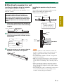
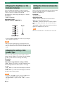
■ Attaching the speaker to a wall
Installing the speaker using the keyholes
You can attach the speaker to a wall using
commercially available screws (#8, Diameter: 7 to 9
mm (1/4” to 3/8”)).
1 Attach the supplied mounting template on
a wall and mark the holes of the mounting
template.
2 Remove the mounting template and then
install the commercially available screws
at the marks.
3 Hang the speaker on the screws using the
keyholes on the back of the speaker.
Installing the speaker using the screw
holes
You can also use the screw holes on the rear of the
speaker for installing the speaker using a
commercially available rack etc.
• Attach the speaker to a rack or wall. Do not attach the
speaker to a wall that is made of weak materials such as
plaster or veneered woods. Doing so may cause the
speaker to fall.
• Use commercially available screws that can support the
weight of the installation.
• Make sure you use specified screws to attach the speaker.
Using clamps other than specified screws, such as short
screws, nails, or two-sided tape, may cause the speaker to
fall.
• When connecting the speaker, fix the speaker cables in
place where they will not become loose. If your foot or
hand accidentally gets caught on a loose speaker cable, the
speaker may fall.
• After attaching the speaker, check that the speaker is fixed
securely. Yamaha will bear no responsibility for any
accidents caused by improper installations.
When installing the speaker on a wall, all
installation work must be performed by a
qualified contractor or dealer. The customer
must never attempt to perform this installation
work. Improper or inadequate installation could
cause the speaker to fall, resulting in personal
injury.
Tapes or thumbtacks
Mark
4 to 6 mm (3/16” to 1/4”)
Diameter:
7 to 9 mm or
more (#8, 1/4”
to 3/8” or more)
Notes
Screw holes
Hole depth: 14 mm (9/16”)
Diameter: 6 mm (1/4”)
Pitch: 256 mm (10-1/16”)
256 mm
(10-1/16”)
37 mm (1-7/16”)
Rack etc.
14 mm (9/16”)
Screw
(M6)
Screw
hole
Min 7 mm (1/4”)
NS-BR300

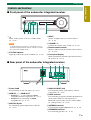
12 En
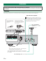
Follow the procedure below to connect the subwoofer integrated receiver and the external components.
Connection
• Do not connect the power cable until all connections are completed.
• Do not use excessive force when inserting the cable plug. Doing so may damage the cable plug and/
or terminal.
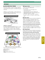
Overview
See “Connecting Blu-ray disc player or set-top box”.
(☞ P. 13)
Indoor FM antenna (supplied)
y
If the radio wave reception is weak in your area
or you want to improve the radio wave reception,
we recommend that you use an outdoor antenna.
For details, consult your nearest authorized
Yamaha dealer or Service Center.
See “Using optional
equipment”. (☞ P. 18)
To AC wall outlet
y
After you have made all connections, connect the power
cable of the subwoofer integrated receiver.
See “Connecting a TV”. (☞ P. 13)
Twist and pull off the
insulation tube on the
lead wire.
VCR, etc.
Insert into the terminal by
matching the wire color with
the color-coded terminal on
the rear panel.
Brown Red Black Green Gray White

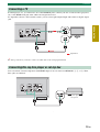
13 En
Connection
PREPARATION
If a DVD player, etc., is connected to one of the HDMI IN jacks, connect your TV or video monitor (projector,
etc.) to the HDMI OUT jack of the subwoofer integrated receiver.
To output the sound of a TV from this system, you can select optical digital input and connect to digital output
jack.
y
For analog connection, you need to connect an audio cable to the analog input terminal.
You can connect external components with HDMI output. You can select from HDMI IN 1, 2, or 3. These
three jacks are identical.
Connecting a TV
TV
Signal flow
Connecting Blu-ray disc player or set-top box
Blu-ray disc player or
set-top box

14 En
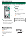
BASIC OPERATION
Once you have finished all cable connections and remote control operation, follow the procedure below to start
basic playback operation.
1 Press .
This system is turned on and the STATUS
indicator lights green.
y
This system has the auto-sleep function, which will
automatically switch the system to turn off if the
system is left turned on for 24 hours without any
operation being performed.
2 Press one of the input buttons to select
an input source.
3 Start playback on the selected external
component.
For information on the external component, refer
to the instruction manual for the product.
4 Press VOLUME +/– to adjust the volume
level.
y
To turn off the volume temporarily, press MUTE.
While the mute function is activated, the VOLUME
indicator flashes. To resume the volume, press MUTE
again or press VOLUME +/–.
When sound of HDMI is output from the TV, the
volume level does not change if you press VOLUME
+/–.
■ Using the remote control
Basic playback operation
1
2
4
Note
Press again to set the system to
standby mode.
When the “HDMI CONTROL” is set to “ON”, the
STATUS indicator lights red. When the “HDMI
CONTROL” is set to “OFF”, the STATUS indicator
turns off. (☞ P. 21)
Within 6 m (20’)
Use the remote control within 6 m (20’) of the
subwoofer integrated receiver and point it toward the
remote control sensor.
• Be careful not to spill liquid on the remote control.
• Be careful not to drop the remote control.
• Do not leave the remote control in a place that is:
– hot or humid, such as near a heater or in a bathroom
–extremely cold
–dusty
Notes

BASIC
OPERATION
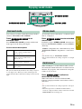
15 En
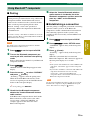
You can enjoy a realistic sound effect using Yamaha’s
exclusive AIR SURROUND XTREME.
Press SURROUND MODE to set
surround mode.
Press SURROUND MODE repeatedly until desired
mode appears in the front panel display.
Surround mode descriptions
y
The system automatically memorizes the settings assigned
to each input source. When you select another input, the
system automatically recalls the last settings for the selected
input.
An extended sound is achieved for a 2 channel source
such as a CD player.
Press STEREO MODE to enter extended
stereo mode.
Each time you press STEREO MODE, the function is
turned on (EXTENDED STEREO) and off (STEREO)
alternately.
“STEREO”: Reproduces the sound without any effect.
“EXTENDED STEREO”: Reproduces a wider stereo
image.
y
• The default setting is “EXTENDED STEREO”.
• The system memorizes the settings assigned to each input
source.
While watching TV, use this function when you feel
uncomfortable with the difference in volume between
channels, TV programs, and commercials to keep the
volume at an even level.
Press UNIVOLUME to activate or
deactivate the function.
When UniVolume is activated, UNIVOLUME
indicator is displayed and the sound volume of TV is
uniformed.
y
• The system memorizes the setting assigned to each input
source.
• When the input source is DOCK and UniVolume is
activated, compressed music enhancer function is invalid
(ENHANCER indicator disappears).
Enjoying sound modes
SURROUND MODE
STEREO MODE
UNIVOLUME
Surround mode
MOVIE This mode is useful when you enjoy
movie contents on media such as
Blu-ray disc, etc.
MUSIC This mode is useful when you listen to
music contents on media such as
Blu-ray disc, etc.
SPORTS This mode is useful when you enjoy
sports programs or TV news.
GAME This mode is useful when you enjoy
video games.
Stereo mode
UniVolume™

16 En
■ Automatic preset
You can store up to 40 FM stations (01 to 40).
1 Press OPTION to enter OPTION menu.
“AUTO PRESET” appears firstly in the front
panel display.
2 Press (Center).
y
Press PRESET / repeatedly to select a preset
number to which the first station will be stored.
After approximately 5 seconds, automatic
presetting starts from the lowest frequency and
proceeds through higher frequencies. When the
frequency is stored, the TUNED indicator lights
up.
When automatic preset tuning is completed, the front
panel display shows message “Preset Complete” for
three seconds firstly and returns to OPTION menu
secondly.
y
Press RETURN while searching automatically, automatic
preset is stopped.
• Any stored station data existing under a preset number is
cleared when you store a new station under the same
preset number.
• If the number of received stations does not reach 40,
automatic preset tuning automatically stops after
searching for all the available stations.
• Only the station with strong signals can be stored. If the
desired station is not stored, or a station is not stored to the
desired preset number, preset the station manually.
(☞ P. 17)
Listening to FM broadcasts
Basic tuning operation
Editing the preset FM station
FM
Sets the input to FM.
TUNING /
Press to change the frequency
by 1 step, or press and hold to
search stations automatically.
PRESET /
Select the preset FM
stations.
INFO
Selects the information
displayed in the front panel
display.
OPTION
Enters OPTION menu
when the input is set to FM.
Cursor in OPTION
menu
MEMORY
Stores preset stations
manually.
RETURN
Returns to the previous
menu or cancels the
operation.
Notes

17 En
Listening to FM broadcasts
BASIC
OPERATION
■ Manual station preset
Use this feature to preset your desired station
manually.
1 Tune into a radio station you want to
preset.
2 Press MEMORY.
“MANUAL PRESET” appears in the front panel
display, followed soon by the preset number to
which the station will be registered.
y
By pressing down MEMORY for more than 2
seconds. The station is registered to the lowest empty
preset number or a preset number one higher than the
last preset number.
3 Press PRESET / to select the preset
number (01 to 40) to which the station will
be registered.
When you select a preset number to which no
station is registered, EMPTY indicator appears on
the display. When you select a registered preset
number, a registered frequency is displayed on the
right of the preset number.
y
To cancel registration, press RETURN on the remote
control or leave the tuner without any operations for
about 30 seconds.
4 Press MEMORY again to register.
■ Clearing the preset station
1 Press OPTION to enter OPTION menu.
2 Display “CLEAR PRESET” using the
cursor and press (Center).
Preset number and the frequency appears in the
display.
y
You can cancel the operation and return to OPTION
menu by pressing RETURN on the remote control.
3 Select the preset number of the registered
station you want to clear using the cursor
/ and press (Center).
The preset station registered to the selected preset
number is cleared. To clear the registration of
multiple preset numbers, repeat the above steps.
To end the operation, press OPTION.
■ Using the monaural
reception mode
When the signal of the desired FM station is too weak,
set the reception mode to “MONO” to increase signal
quality.
1 Press OPTION to enter OPTION menu.
2 Display “STEREO/MONO” by using the
cursor and press (Center).
3 Select “MONO” to set the reception mode
to monaural by using the cursor / .
■ Switching the information
display
Each time you press INFO, the information display
changes as follows:
Information type
• SURROUND MODE
Displays the surround mode or stereo mode.
• FREQUENCY
Displays the frequency and preset number.
• PROGRAM SERVICE (PS)
Displays the currently received Radio Data System
program.
• PROGRAM TYPE (PTY)
Displays the type of the currently received Radio
Data System program.
• RADIO TEXT (RT)
Displays the information of the currently received
Radio Data System program.
• CLOCK TIME (CT)
Displays the current time.
Europe and Russia models only

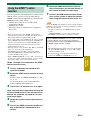
18 En
This system is equipped with a DOCK terminal, which allows you to connect a Yamaha iPod universal dock (such
as YDS-11, sold separately) or a Yamaha Bluetooth wireless audio receiver (such as YBA-10, sold separately) to
enjoy music contents stored in your Bluetooth component (such as a portable music player or computer equipped
with Bluetooth transmitter, etc.). Connect this equipment to the DOCK terminal of the subwoofer integrated
receiver using its dedicated cable.
y
When DOCK is selected as the input source, compressed music enhancer function is activated automatically and enhances
your listening experience by regenerating the missing harmonics in a compressed music format such as MP3.
Once you have stationed your iPod in the Yamaha iPod universal dock connected to the DOCK terminal of the
subwoofer integrated receiver, you can enjoy playback of your iPod.
Supported iPod
iPod (Click and Wheel including iPod classic)
iPod nano
iPod mini
iPod touch
Battery charge feature
This system charges the battery of an iPod stationed in the Yamaha iPod universal dock connected to the DOCK
terminal of the subwoofer integrated receiver, even when this system is turned off. “Charging” appears in the
front panel display.
• Some features may not be available depending on the model or the software version of your iPod.
• For a complete list of status messages that appear in the front panel display, see the “iPod” section in “Troubleshooting” (☞
P. 26).
• Be sure to set the volume to minimum before docking or removing your iPod.
• To playback an iPod, select DOCK for input source.
• Refer to the instruction manual of your Yamaha iPod universal dock for details.
Using optional equipment
Connecting dock
Using iPod™
Notes
Yamaha iPod universal dock
(such as YDS-11, sold separately)
Yamaha Bluetooth wireless audio receiver
(such as YBA-10, sold separately)
Connect either component.

19 En
Using optional equipment
BASIC
OPERATION
■ Pairing
For details, refer to the instruction manual of Yamaha
Bluetooth wireless audio receiver.
1 Press DOCK to set the input to DOCK.
2 Turn on the Bluetooth component you
want to pair with, and then enter pairing
mode.
Refer to the instruction manual of your Bluetooth
component for details.
3 Press OPTION.
OPTION menu for DOCK input appears in the
display.
4 Press the cursor to select “PAIRING”
and press (Center).
“Searching...” appears when the pairing starts.
While the Yamaha Bluetooth wireless audio
receiver is in pairing mode, the DOCK indicator
flashes in the front panel display.
y
To cancel pairing, press RETURN.
5 Check that the Bluetooth component
detects the Yamaha Bluetooth wireless
audio receiver.
If the Bluetooth component detects the Yamaha
Bluetooth wireless audio receiver, the audio
receiver name (“YBA-10 YAMAHA” for
example) appears in the device list of the
Bluetooth component.
6 Select the Yamaha Bluetooth wireless
audio receiver in the device list of the
Bluetooth component, and then enter the
pass key “0000” on the Bluetooth
component.
■ Establishing a connection
After the pairing is completed, perform the connecting
operation on the system or on the Bluetooth
component to enable communication between them.
The connecting operation on the system is only
available for the most recently connected Bluetooth
component.
1 Press DOCK to set the input to DOCK.
2 Press OPTION to enter OPTION menu.
“CONNECT” appears firstly in the front panel
display.
3 Press (Center).
“Searching...” appears firstly in the front panel
display.
When the system finds the last connected
Bluetooth component, “BT connected” appears in
the front panel display for 3 seconds.
y
• If the system cannot find the last connected Bluetooth
component, “Not found” appears in the front panel
display.
• If you want to establish a connection with a Bluetooth
component other than the one most recently
connected to, connect from that Bluetooth
component. Refer to the instruction manual of your
Bluetooth component for details.
To disconnect the Bluetooth wireless audio receiver from
the Bluetooth component, display OPTION menu again,
select “Disconnected,” and press (Center).
Using Bluetooth™ components
About “Pairing”
Pairing must be performed before using a Bluetooth
component with the Yamaha Bluetooth wireless
audio receiver connected to the system for the first
time or if the registered pairing data has been
deleted. “Pairing” refers to the operation of
registering a Bluetooth component for Bluetooth
communications.
y
To ensure security, a time limit of 8 minutes is set for the
pairing operation. Please read and fully understand all the
instructions before starting.
Note
Note

20 En
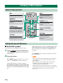
USEFUL OPERATION
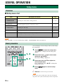
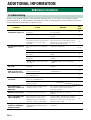
■ Setup menu list
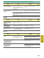
If the “SP TYPE” is set to the default setting (“BAR”), “SP DISTANCE” will not be displayed.
You can change various settings of this system using
the setup menu.
1 Press SETUP to enter the setup menu.
“SW LEVEL” is displayed in the front panel
display.
2 Press the cursor / to select menu
and press (Center).
The current setting is displayed.
3 Press the cursor / to adjust the
value of each menu.
Press and hold the cursor / to change the
setting value faster.
4 Press SETUP again to exit the setup
menu.
y
Press RETURN to return to the previous menu.
If you do not operate within 30 seconds after entering the
setup menu, the system automatically exits the setup menu.
Setup menu
Overview
Item Description of function Page
1: SW LEVEL
Adjusting the volume balance during playback ☞ P. 212: CENTER LEVEL
3: SUR. LEVEL
4: TONE BASS
Adjusting high/low frequency sound (tone control) ☞ P. 21
5: TONE TREBLE
6: AUDIO DELAY Adjusting the audio delay ☞ P. 21
7: HDMI AUDIO Setting the audio output ☞ P. 21
8: HDMI CONTROL Switching on/off the HDMI control function ☞ P. 21
9: DISPLAY MODE Changing the brightness of the front panel display ☞ P. 22
10: SP TYPE Changing the setting of the speaker type ☞ P. 22
11: SP DISTANCE Setting the distance between the speakers ☞ P. 22
Note
Basic procedure
1, 4
2, 3
Note
Sayfa yükleniyor...
Sayfa yükleniyor...
Sayfa yükleniyor...
Sayfa yükleniyor...
Sayfa yükleniyor...
Sayfa yükleniyor...
Sayfa yükleniyor...
Sayfa yükleniyor...
Sayfa yükleniyor...
Sayfa yükleniyor...
Sayfa yükleniyor...
-
 1
1
-
 2
2
-
 3
3
-
 4
4
-
 5
5
-
 6
6
-
 7
7
-
 8
8
-
 9
9
-
 10
10
-
 11
11
-
 12
12
-
 13
13
-
 14
14
-
 15
15
-
 16
16
-
 17
17
-
 18
18
-
 19
19
-
 20
20
-
 21
21
-
 22
22
-
 23
23
-
 24
24
-
 25
25
-
 26
26
-
 27
27
-
 28
28
-
 29
29
-
 30
30
-
 31
31


diğer dillerde
- español: Yamaha YHT-S400 El manual del propietario
- français: Yamaha YHT-S400 Le manuel du propriétaire
- italiano: Yamaha YHT-S400 Manuale del proprietario
- svenska: Yamaha YHT-S400 Bruksanvisning
- Deutsch: Yamaha YHT-S400 Bedienungsanleitung
- English: Yamaha YHT-S400 Owner's manual
- русский: Yamaha YHT-S400 Инструкция по применению
- suomi: Yamaha YHT-S400 Omistajan opas
- Nederlands: Yamaha YHT-S400 de handleiding
- română: Yamaha YHT-S400 Manualul proprietarului