
Owner´s Manual
Mode d´emploi
Bedienungsanleitung
Bruksanvisning
Manuale di istruzioni
Manual de instrucciones
Gebruikershandleiding
Инструкция По Эксплуатации
Pre-Amplifier
Préamplificateur
Предусилитель
FrançaisDeutschSvenska
Italiano
EspañolNederlands
Русский
English

2
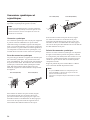
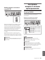
Thank you and congratulations on your purchase of this Yamaha product.
¡
You can enjoy the high-quality stereo sound of this preamplier at home.
¡
This Owner’s Manual describes the unit’s features, connection procedures, and operations.
¡
To use the product properly and safely, we suggest that you read this manual and Safety Brochure
(separate booklet) thoroughly.
Keep the manual in a safe, accessible place for future reference.
You can download a PDF version of this manual from the following Yamaha website.
https://download.yamaha.com/
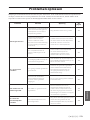
Features
¡
Left-right symmetrical design creates a bookmatched structure
¡
Class A operation of full-stage, full-oating balanced signal transmission from input to output
¡
Full-oating and balanced phono EQ amplier with balanced inputs
¡
High-accuracy controls that employ a proprietary bearing structure and high-rigidity lever switches
¡
Twin transformer designed specically for audio, which is completely separate from the control power
supply
¡
Stable mechanical grounding construction dramatically lessens the impact of external vibration.
¡
Tone control circuit that features a proprietary parallel volume system
¡
Newly-designed brass spiked feet
¡
Gain control function that enables ultra ne volume adjustment
About this manual
¡
The illustrations as shown in this manual are for instructional purposes only.
¡
The company names and product names in this manual are the trademarks or registered trademarks of
their respective companies.
¡
“
WARNING
” describes precautions to be followed to avoid the possibility of serious injury or
even death.
¡
“
CAUTION
” describes precautions to be followed to avoid the possibility of injury.
¡
“
NOTICE
” describes precautions to be followed to avoid the possibility of malfunction/damage to the
product, or damage to data.
¡
“
Note
” describes supplemental information about the product.
¡
Before starting to use the product, please be sure to read the separate “Safety Brochure”.
English

3
English
Table of contents
Features . . . . . . . . . . . . . . . . . . . . . . . . 2
About this manual . . . . . . . . . . . . . . . . .2
Supplied accessories . . . . . . . . . . . . . . . . 4
Maintenance . . . . . . . . . . . . . . . . . . . . . 4
Mirror-nish side panels . . . . . . . . . . . . .4
Surfaces other than the mirror-nish
side panels . . . . . . . . . . . . . . . . . . . . . 4
Part Names and Functions
Front panel . . . . . . . . . . . . . . . . . . . . . . 6
Rear panel. . . . . . . . . . . . . . . . . . . . . .10
Balanced and unbalanced connections . . 14
Remote control . . . . . . . . . . . . . . . . . . 16
Installing batteries in the remote control
. . 18
Operating the remote control . . . . . . . . 18
Connections
Connecting an external component . . . . . 20
Connecting a turntable . . . . . . . . . . . . 22
Connecting a recording component . . . . 22
Connecting another preamplier . . . . . . 23
Connecting a power amplier and
an active subwoofer . . . . . . . . . . . . . . 23
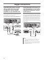
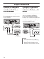
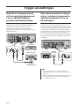
Trigger connections . . . . . . . . . . . . . . . 24
Controlling the power on-and-o operation
of a connected component, such as
a power amplier, in sync with this unit . . 24
Controlling the unit’s power on-and-
o operation in sync with a connected
component, such as an AV receiver. . . . .24
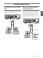
Remote connections . . . . . . . . . . . . . . . 25
Operating the unit from another room . . 25
Remote connection between Yamaha
components . . . . . . . . . . . . . . . . . . . 25
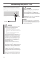
Connecting the power cord. . . . . . . . . . .26
Operations
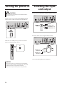
Turning the power on . . . . . . . . . . . . . . 28
Selecting the input and output . . . . . . . . 28
Selecting the input from the EXT.IN jacks
. . 29
Adjusting the turntable input setting . . . . 29
PHONO selector . . . . . . . . . . . . . . . . . 29
Subsonic lter . . . . . . . . . . . . . . . . . . 30
Adjusting the volume level . . . . . . . . . . . 30
Lowering the volume level momentarily
. . 31
Adjusting the tone . . . . . . . . . . . . . . . . 31
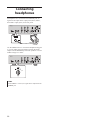
Connecting headphones . . . . . . . . . . . . 32
Reference Materials
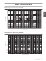
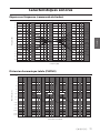
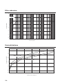
General specications . . . . . . . . . . . . . . 34
Block diagram . . . . . . . . . . . . . . . . . . . 36
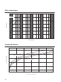
Audio characteristics . . . . . . . . . . . . . . .37
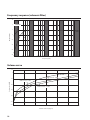
Frequency response (tone control) . . . . . 37
Total harmonic distortion (PHONO). . . . .37
Frequency response (subsonic lter) . . . .38
Volume curve. . . . . . . . . . . . . . . . . . .38
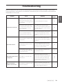
Troubleshooting. . . . . . . . . . . . . . . . . .39
Index . . . . . . . . . . . . . . . . . . . . . . . . . 41

4
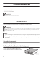
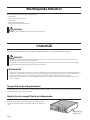
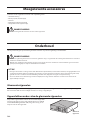
Supplied accessories
Please make sure that the following accessories are included in the package.
• Remote control
• Batteries (AAA, R03, UM-4) (x2)
• Power cord
• Owner’s Manual (this book)
• Safety Brochure (separate booklet)
WARNING
Do not use the supplied power cord for other devices.
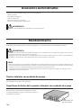
Maintenance
To use this product for an extended period of time, we recommend that you maintain it regularly.
WARNING
• Check the power cord regularly to see if it is dusty. If so, wipe o the dust completely. Otherwise, re or electric shock might be
caused.
• Do not use aerosol or ammable gas spray for cleaning or lubrication. Otherwise, ammable gas will build up inside the unit,
causing possible explosion or re.
NOTICE
• Use a dry soft cloth to clean the unit. Using cleaning agents, such as benzene or thinner, detergent, or chemically-treated cloth
might cause color changes or deterioration of the surface. If the surface gets very dirty, damp a cloth with detergent (diluted
with water), wring the cloth tightly, and wipe o the dirt.
• If you wipe the surface area in the vicinity of the Yamaha logo with force, the logo might peel o or ber from the cloth might
stick to the surface.
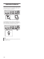
Mirror-nish side panels
We recommend that you use a cleaning cloth such as those made for pianos. If the surface is very dirty, use a soft cloth
that is damp with water and wrung tightly.
Surfaces other than the mirror-nish side panels
Wipe other surfaces using a soft dry cloth. If the surface gets
very dirty, dampen a cloth with detergent diluted in water,
wring the cloth tightly, and then wipe the dirt from the surface.
Mirror-nish
side panels

5
English
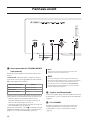
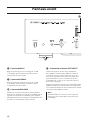
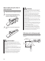
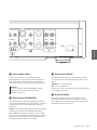
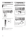
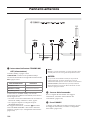
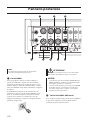
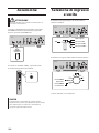
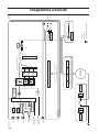
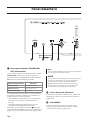
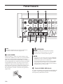
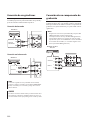
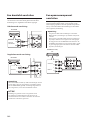
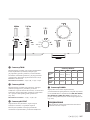
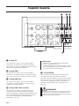
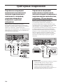
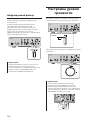
Part Names and Functions
This section lists the names and describes the function of
various parts on the front and rear panels, and the remote control.

6
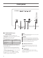
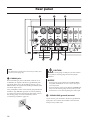
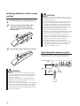
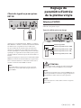
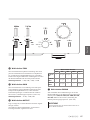
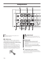
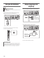
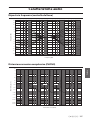
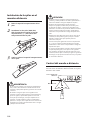
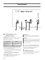
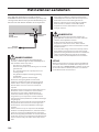
Front panel
A.
STANDBY/ON/OFF (Power)
switch/ indicator
Turns the power to the unit on (standby) or off.
STANDBY/ON
: Switches between standby and on using
the
A
AMP key on the remote control.
OFF
: Turns the power to the unit off.
Power status Indicator
On mode Lit brightly
Standby mode Lit dimly
O mode Off
The unit will enter standby mode not only when you
press the AMP key on the remote control, but also in one
of the following events:
• If the unit is powered on but not operated for eight
hours while the auto power standby function is turned
on, or
• If you turn off the power to the device that is connected
to this unit’s TRIGGER IN jack.
For more information, refer to “
Q
AUTO POWER
STANDBY switch” in the “Rear panel” section (page
13) and to “Trigger connections” (page 24).
Note
After you turn on the unit, it will take a few seconds before
the unit can reproduce sound.
NOTICE
If you plan not to use the unit for an extended period of
time, be sure to unplug the power cord from the AC outlet.
Even when the STANDBY/ON/OFF (Power) switch is turned
o (the power indicator is dark), a minimal amount of
electric current is still owing to the unit.
B.
Remote control sensor
Receives signals from the remote control. For more
information, refer to “Operating the remote control”
(page 18).
C.
PHONES jack
Connect your headphones here to listen to music
privately. For more information, refer to “Connecting
headphones” (page 32).

7
English
D.
TRIM selector
Switches the headphone amp gain. The unit will adjust
the volume level when headphones are plugged in to
avoid sudden changes in volume by modifying the level
balance between the audio output from the PHONES jack
and from the speakers.
Choices
: −6 dB, 0 dB, +6 dB, +12 dB
E.
GAIN selector
Switches the preamp gain. The unit will smoothly adapt to
the power amp gain and speaker sensitivity, enabling you
to make ne volume adjustments. For more information,
refer to “Adjusting the volume level” (page 30).
Choices
: −12 dB, −6 dB, 0 dB
F.
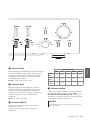
OUTPUT selector
Species which OUTPUT jacks will output signals, as
follows:
Use this selector if multiple power ampliers are
connected.
OUTPUT selector
OFF ALL BAL LINE1 LINE2
BAL
jacks
—
Output Output
— —
LINE 1
jacks
—
Output
—
Output
—
LINE 2
jacks
—
Output
— —
Output
G.
PHONO selector
Indicates the type of cartridge installed on the turntable
that is connected to the PHONO jacks on the rear panel
(
MM, MC 300, MC 100, MC 30, MC 10
). For
more information, refer to “Adjusting the turntable input
setting” (page 29).
NOTICE
Before you replace the cartridge, be sure to turn o the
power to this unit.

8
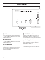
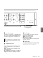
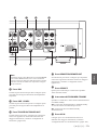
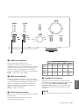
H.
BASS control
Adjusts the low-frequency response in the range from
−10 dB to +10 dB (in 0.5 dB steps). The center position
produces a at response.
I.
TREBLE control
Adjusts the high-frequency response in the range from
−10 dB to +10 dB (in 0.5 dB steps). The center position
produces a at response.
J.
BALANCE control
Adjusts the audio output balance between the left and
right speakers in the range from L (the right channel is
muted) to R (the left channel is muted) to compensate
for sound imbalances caused by speaker locations or
listening room conditions.
K.
EXT. DIRECT switch/indicator
If you press the EXT. DIRECT switch once, the EXT.
DIRECT indicator will light up, and the audio source
input at the EXT. IN jacks will be output at the connected
output jacks. For more information, refer to “Connecting
another preamplier” (page 23) and “Selecting the
input and output” (page 28).
If you press the EXT. DIRECT switch again or rotate
the INPUT selector, the signal specied by the INPUT
selector will become the input source, and the EXT.
DIRECT indicator will turn off.
Note
If EXT. DIRECT is selected, no signal will be output at the
LINE 2 OUT (recording) jacks nor at the PHONES jack.
Front panel

9
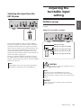
English
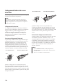
L.
INPUT selector/indicator
Enables you to select the input source to play back.
Options are:
PHONO, PHONO BAL, TUNER, CD, BAL 1,
BAL 2, LINE 1, and LINE 2
. The indicator for the selected
input source lights up.
Note
If LINE 2 is selected here, audio signals will not be output at
the LINE 2 OUT (recording) jacks.
M.
SUBSONIC FILTER switch
Toggles between
ON
(enabled) and
THROUGH
(disabled)
for the subsonic lter. For more information, refer to
“Adjusting the turntable input setting” (page 29).
Note
If the INPUT selector is set to any option other than PHONO
or PHONO BAL, the lter will be disabled.
N.
AUDIO MUTE switch/indicator
Press this switch to reduce the current volume level by
approximately 20 dB. The indicator will light up. Press
again to restore the audio output to the previous volume
level. The indicator will turn off.
O.
VOLUME control
Adjusts the volume level. This setting will not affect the
output level at the LINE 2 OUT (recording) jacks.
Note
The VOLUME control will not aect the volume level if EXT.
DIRECT is selected as the input source. To adjust the volume
level, use the volume control on the external preamplier
or another component connected to the EXT. IN jacks.
P.
Feet
If the unit is unstable, adjust the height of the feet as
needed by rotating them.

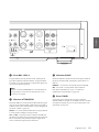
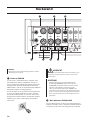
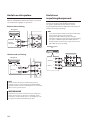
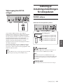
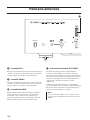
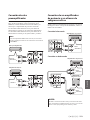
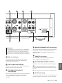
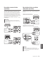
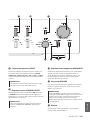
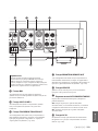
10
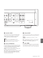
Note
For information regarding the connection procedure, refer
to “Connections” (page19).
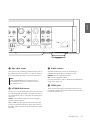
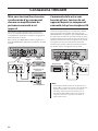
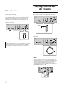
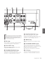
A.
PHONO jacks
RCA and XLR-type jacks. If the INPUT selector is set
to PHONO, the signals at the RCA-type PHONO jacks
will be the input source. If the INPUT selector is set to
PHONO BAL, the signals at the XLR-type PHONO jacks
will be the input source.
Your preamplier comes with a shorting plug installed on
each RCA-type PHONO input jack. If you are planning
to connect an external component to these jacks, remove
the shorting plugs. For more information, refer to
“Connecting a turntable” (page 22).
PHONO
CAUTION
Handle the shorting plugs carefully. Do not allow children
to play with the shorting plug; otherwise they might
swallow it.
NOTICE
• Shorting plugs are intended for unused INPUTS ONLY;
using them on OUTPUTS can cause serious damage to
your components.
• If you are planning not to use the RCA-type PHONO input
jacks, insert the shorting plugs into the jacks to prevent
random static or noise from degrading the audio signal.
B.
SIGNAL GND (ground) terminal
If you connect your turntable to the RCA-type PHONO
input jacks, also connect the turntable to this terminal.
Doing so may reduce noise.
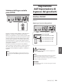
Rear panel

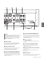
11
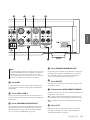
English
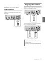
C.
BAL 1/BAL 2 jacks
These are two sets of XLR-type balanced input jacks. If
the INPUT selector is set to BAL 1 or BAL 2, signals at
the corresponding XLR jacks will be the input source.
Note
Set the ATTENUATOR selector and PHASE selector
appropriately for the playback components that are
connected to the unit.
D.
ATTENUATOR selector
Enables you to set the allowable input level for the XLR-
type balanced input jacks (BAL 1 and BAL 2 jacks). For
more information, refer to “Adjusting the volume level”
(page 30).
BYPASS
: The allowable input level will not change.
Usually select this option.
ATT. (−6 dB)
: The input gain will be lowered by 6 dB
to raise the allowable input level. Select this option if
the audio output from the connected component sounds
distorted.
E.
PHASE selector
Species the HOT pin position for the XLR-type
balanced input jacks (BAL 1 and BAL 2 jacks).
NORMAL
: Pin #2 is specied as HOT.
INV.
: Pin #3 is specied as HOT.
For more information, refer to “Balanced and unbalanced
connections” (page 14).
F.
TUNER jacks
These are RCA input jacks. If the INPUT selector is set
to TUNER, signals at these jacks will be the input source.
Connect your tuner here.

12
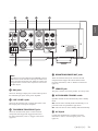
G.
CD jacks
These are RCA input jacks. If the INPUT selector is set
to CD, signals at these jacks will be the input source.
Connect your CD player here.
H.
LINE 1 jacks
These are RCA input jacks. If the INPUT selector is set
to LINE 1, signals at these jacks will be the input source.
I.
LINE 2 IN jacks
These are RCA input jacks. If the INPUT selector is set
to LINE 2, these jacks will be the input source.
J.
LINE 2 OUT (recording) jacks
These are RCA input jacks for recording. These jacks
normally output the input source signals selected via the
front panel or remote control. For information on the
connection procedure, refer to “Connecting a recording
component” (page 22).
Note
• Connect the LINE 2 IN jacks and LINE 2 OUT (recording)
jacks to the same component.
• The LINE 2 OUT (recording) jacks will not output any
signals if the INPUT selector is set to LINE 2 or the EXT.
DIRECT switch is pressed.
K.
EXT.IN jacks
These jacks feature XLR-type input jacks and RCA
input jacks. If the EXT. DIRECT switch is pressed,
signals at these jacks will be the input source. Connect
your preamplier here. For more information, refer to
“Connecting another preamplier” (page 23).
CAUTION
You cannot adjust the volume level of the signals input at
the EXT. IN jacks. Therefore, be sure to connect to the EXT.
IN jacks a component that features a volume control.
Rear panel

13
English
Note
The volume level is xed. Operating the VOLUME control or
GAIN selector on this unit will not change the volume level
of the signal from the EXT. IN jacks. Adjust the volume level
using the volume control on the component connected to
the EXT. IN jacks.
L.
BAL jacks
These are XLR-type output jacks. Connect these jacks to
the balanced input jacks on the power amplier.
M.
LINE 1/LINE 2 jacks
These are RCA output jacks. Connect these jacks to the
RCA input jacks on the power amplier.
N.
TRIGGER IN/TRIGGER OUT jacks
These are monaural mini jacks. Connect external
components that support the trigger function here.
For more information, refer to “Trigger connections”
(page 24).
O.
REMOTE IN/REMOTE OUT jacks
These are monaural mini jacks. Connect external
components that support the remote function here.
For more information, refer to “Remote connections”
(page 25).
P.
SERVICE jack
This jack is used to service the product. It is rarely used.
Q.
AUTO POWER STANDBY switch
Species whether the unit automatically enters standby
mode.
ON
: The unit enters standby mode automatically if it is
powered on but not operated for eight hours.
OFF
: The unit does not enter standby mode automatically.
R.
AC IN jack
Connect the supplied power cord here. For more
information, refer to “Connecting the power cord”
(page 26).

14
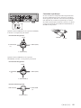
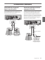
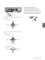
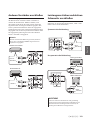
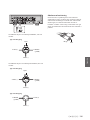
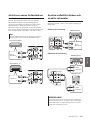
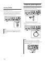
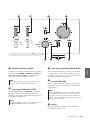
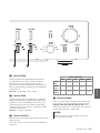
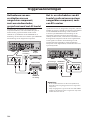
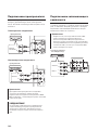
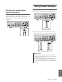
Balanced and unbalanced
connections
This unit features XLR-type balanced jacks and RCA-
type unbalanced input jacks.
Note
Do not use balanced and unbalanced connections between
two components simultaneously. Doing so would create a
ground loop that could generate static and noise.
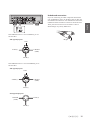
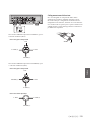
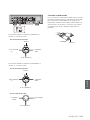
Balanced connection
A balanced connection is designed to cancel and prevent
unwanted noise. Since longer cables tend to pick up
more noise, a balanced connection is useful if you need
to use long cables. Generally, if your components feature
balanced outputs, you should use balanced connections.
Jacks for balanced connections
XLR-type jacks on this unit are used for balanced
connections. The input and output jacks utilize different
designs. Input jacks are female, and output jacks are
male. For balanced connections, balanced cables with
XLR connectors are used. Connect a male connector
on the cable to a female jack on the unit, and connect a
female connector to a male jack on the unit.
3
2
2
1
1
3
Lever
XLR connector (male)XLR jack (female)
When connecting a cable to an input jack, be sure to
align the pins on the connector with the holes in the jack,
and then insert the connector into the jack until you hear
a click. To remove the cable, while pressing and holding
down the lever on the input jack on the unit, pull out the
male XLR connector from the jack.
3
1
1
2
2
3
XLR connector (female)XLR jack (male)
Lever
When connecting a cable to an output jack, be sure to
align the holes on the connector with the pins on the jack,
and then insert the connector into the jack until you hear
a click. To remove the cable, while pressing and holding
down the lever on the female XLR connector, pull it out
from the jack.
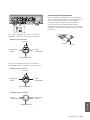
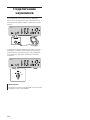
Balanced connection polarity
When making a balanced connection, you must set the
polarity correctly. Generally, pin #2 is Hot, but sometimes
pin #3 can be Hot. Refer to the owner’s manual for the
connected component to learn which pin at the output
jack is Hot.
To set the polarity for the BAL 1 and BAL 2 input jack
pins, use the PHASE selector on the rear panel.
Note
• The PHONO and EXT. IN jacks do not feature a PHASE
switch. The pin polarity of these jacks is standard and
xed.
• Pin #2 is Hot on Yamaha players.

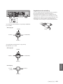
15
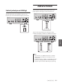
English
If the PHASE selector is set to NORMAL, pin #2
becomes Hot.
XLR-type input jack
1: Ground
(earth)
3: Cold (−)
2: Hot (+)
Lever
If the PHASE selector is set to INVERTED, pin #3
becomes Hot.
XLR-type input jack
1: Ground
(earth)
3: Hot (+)
2: Cold (−)
Lever
XLR-type output jack
1: Ground
(earth)
3: Cold (−)
2: Hot (+)
Unbalanced connection
If you are connecting an audio component that features
only standard RCA jacks, use the RCA jacks on this unit
for unbalanced connections. For unbalanced connections,
unbalanced cables with RCA connectors should be used.
These jacks and connectors do not feature a male or
female design nor polarity differences.
Pin
Ring

16
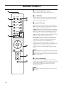
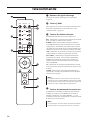
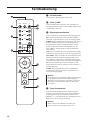
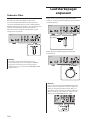
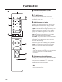
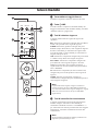
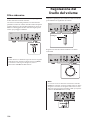
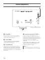
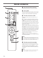
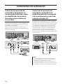
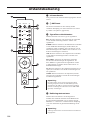
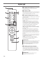
Remote control
A.
Infrared signal transmitter
Outputs infrared control signals toward the unit.
B.
A
AMP key
Turns on the power to the unit or switches it to standby
mode. For more information regarding standby mode,
refer to “Front panel” (page 6).
C.
Input select keys
Enable you to select the input source to be played back.
BAL
: Selects the component connected to the XLR-type
BAL 1 or BAL 2 jacks as the input source.
PHONO
: Selects the turntable connected to the PHONO
jacks (XLR-type or RCA) as the input source. Press the
BAL key to select the source at the XLR-type jacks, or
the UNBAL key to select the source at the RCA jacks.
LINE
: Selects the component connected to the RCA-type
LINE 1 or LINE 2 jacks as the input source.
EXT. DIRECT
: Selects the component connected to the
EXT. IN jacks as the input source. If EXT. DIRECT is
selected as the input source, audio signals will not be
output at the LINE 2 OUT or PHONES jacks.
CD
: Selects the component (usually, a CD player)
connected to the RCA-type CD jacks as the input source.
TUNER
: Selects the component (usually, a tuner)
connected to the RCA-type TUNER jacks as the input
source.
Note
Audio signals of the selected input source will be output at
the LINE 2 OUT (recording) jacks. If LINE 2 is selected as the
input source, audio signals will not be output at the LINE 2
OUT (recording) jacks.
D.
Tuner control keys
Enable you to control the functions of the connected
Yamaha tuner. Use the BAND key to switch the reception
band, and the PRESET
er
keys to select a preset
station. For more information, refer to the owner’s
manual for your tuner.
Note
Some Yamaha tuner models might not support these key
functions.
AMP CD
BAL
PHONO
LINE
CD
TUNER BAND
PRESET
SOURCE LAYER
EXT.DIRECT
BALUNBAL
21
21
OPEN/CLOSE
VOLUME
MUTE

17
English
E.
A
CD key
Turns on the power to a connected Yamaha CD player, or
switches it to standby mode.
F.
OPEN/CLOSE key
Opens or closes the disc tray of a connected Yamaha CD
player. For more information, refer to the owner’s manual
for your CD player.
Note
Some Yamaha CD player models might not support the
A
CD key and/or
OPEN/CLOSE key functions.
G.
CD player control keys
Enable you to control the functions of a connected
Yamaha CD player. For more information, refer to the
owner’s manual for your CD player.
(Play)
Starts playback.
(Pause)
Pauses playback. Press or to resume playback.
(Stop)
Stops playback.
/ (Skip)
Skips to the next track, or returns to the beginning of
the current track.
SOURCE key
Selects the source to be played on the Yamaha CD
player. The playback source changes each time this key
is pressed.
LAYER key
Toggles the playback layer of a hybrid super audio CD
between “Super audio CD” and “CD.”
Note
Some Yamaha CD player models might not support these
key functions.
H.
VOLUME +/− keys
Adjust the volume level.
Note
The VOLUME +/− keys on the remote control will not aect
the volume level if EXT. DIRECT is selected as the input
source. To adjust the volume level, use the volume control
on the external amplier connected to the EXT. IN jacks.
I.
MUTE key
Reduces the current volume level by approximately
20 dB. Press the key again to restore the audio output to
the previous volume level. Pressing the VOLUME + or
− key on the remote control will also cancel muting.

18
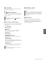
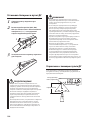
Installing batteries in the remote
control
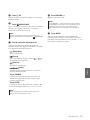
1
Remove the battery compartment cover.
2
Insert two batteries (AAA, R03, UM-4)
according to the polarity markings
(+ and −) on the inside of the battery
compartment.
1
2
3
Reinstall the battery compartment cover.
3
WARNING
• Do not toss the batteries into an open re, or expose
them to high temperatures, such as direct sunlight or
open ame. Otherwise, the battery might explode,
causing re or injury.
• Do not try to recharge non-rechargeable batteries.
Otherwise, batteries might explode or leak, causing
blindness, chemical burns or injury.
• If a battery is leaking, do not touch the liquid. Otherwise,
blindness or chemical burns might be caused. If your
eyes, mouth, or skin comes in contact with the liquid,
immediately wash the site thoroughly with water and
seek medical attention.
CAUTION
• Do not use a new and old batteries at the same time.
Otherwise, re, burns, or irritation due to leaking battery
liquid might be caused.
• Do not use two dierent types of batteries at the same
time. For example, if you use an alkaline battery and
a manganese battery together, or two batteries from
two dierent manufacturers or with dierent product
numbers at the same time, re, burns, or skin irritation
due to leaking battery liquid might be caused.
• Keep the batteries out of the reach of children.
Otherwise, a child might swallow the battery by accident.
Also, leaking battery liquid might cause skin irritation.
• Insert the two batteries according to the polarity
markings (+ and −). Otherwise, re, burns, or skin
irritation due to leaking battery liquid might be caused.
• If you plan not to use the remote control for an
extended period of time, or if the batteries are
exhausted completely, remove them from the remote
control. Otherwise, all batteries will eventually become
exhausted and might leak, causing skin irritation or
damage to the remote control.
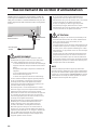
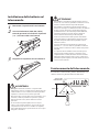
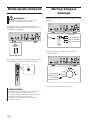
Operating the remote control
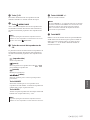
To operate the remote control, aim it directly at the
remote control sensor on the front panel of the unit.
Remote control
sensor
30 30
Within 6 m (20 ft)

19
English
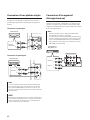
Connections
CAUTION
Turn o the power to all components before making any connections.
NOTICE
• Do not use balanced and unbalanced connections between two components simultaneously. Doing so would create a ground
loop that could generate static and noise.
• If you are planning to connect external components, read and follow the instruction manuals for those components.
Otherwise, this unit or external components might malfunction.
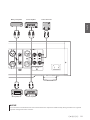
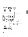
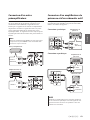
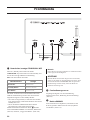
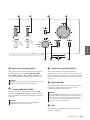
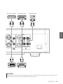
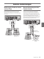
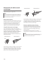
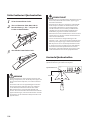
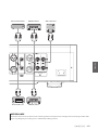
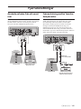
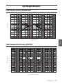
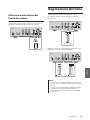
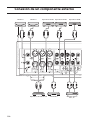
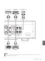
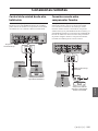
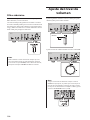
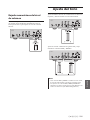
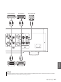
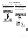
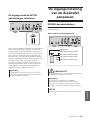
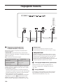
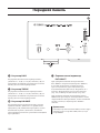
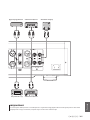
This section explains how to connect the unit to an audio source,
such as a tuner or CD player, and a power amplier.

20
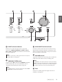
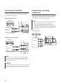
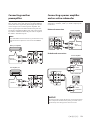
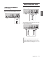
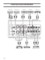
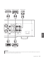
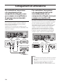
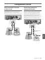
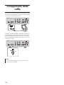
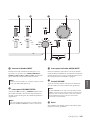
Connecting an external component
Turntable
Network audio player
CD player
Hard disk recorder,
etc.
Tuner
CD playerTurntable BD player
Sayfa yükleniyor...
Sayfa yükleniyor...
Sayfa yükleniyor...
Sayfa yükleniyor...
Sayfa yükleniyor...
Sayfa yükleniyor...
Sayfa yükleniyor...
Sayfa yükleniyor...
Sayfa yükleniyor...
Sayfa yükleniyor...
Sayfa yükleniyor...
Sayfa yükleniyor...
Sayfa yükleniyor...
Sayfa yükleniyor...
Sayfa yükleniyor...
Sayfa yükleniyor...
Sayfa yükleniyor...
Sayfa yükleniyor...
Sayfa yükleniyor...
Sayfa yükleniyor...
Sayfa yükleniyor...
Sayfa yükleniyor...
Sayfa yükleniyor...
Sayfa yükleniyor...
Sayfa yükleniyor...
Sayfa yükleniyor...
Sayfa yükleniyor...
Sayfa yükleniyor...
Sayfa yükleniyor...
Sayfa yükleniyor...
Sayfa yükleniyor...
Sayfa yükleniyor...
Sayfa yükleniyor...
Sayfa yükleniyor...
Sayfa yükleniyor...
Sayfa yükleniyor...
Sayfa yükleniyor...
Sayfa yükleniyor...
Sayfa yükleniyor...
Sayfa yükleniyor...
Sayfa yükleniyor...
Sayfa yükleniyor...
Sayfa yükleniyor...
Sayfa yükleniyor...
Sayfa yükleniyor...
Sayfa yükleniyor...
Sayfa yükleniyor...
Sayfa yükleniyor...
Sayfa yükleniyor...
Sayfa yükleniyor...
Sayfa yükleniyor...
Sayfa yükleniyor...
Sayfa yükleniyor...
Sayfa yükleniyor...
Sayfa yükleniyor...
Sayfa yükleniyor...
Sayfa yükleniyor...
Sayfa yükleniyor...
Sayfa yükleniyor...
Sayfa yükleniyor...
Sayfa yükleniyor...
Sayfa yükleniyor...
Sayfa yükleniyor...
Sayfa yükleniyor...
Sayfa yükleniyor...
Sayfa yükleniyor...
Sayfa yükleniyor...
Sayfa yükleniyor...
Sayfa yükleniyor...
Sayfa yükleniyor...
Sayfa yükleniyor...
Sayfa yükleniyor...
Sayfa yükleniyor...
Sayfa yükleniyor...
Sayfa yükleniyor...
Sayfa yükleniyor...
Sayfa yükleniyor...
Sayfa yükleniyor...
Sayfa yükleniyor...
Sayfa yükleniyor...
Sayfa yükleniyor...
Sayfa yükleniyor...
Sayfa yükleniyor...
Sayfa yükleniyor...
Sayfa yükleniyor...
Sayfa yükleniyor...
Sayfa yükleniyor...
Sayfa yükleniyor...
Sayfa yükleniyor...
Sayfa yükleniyor...
Sayfa yükleniyor...
Sayfa yükleniyor...
Sayfa yükleniyor...
Sayfa yükleniyor...
Sayfa yükleniyor...
Sayfa yükleniyor...
Sayfa yükleniyor...
Sayfa yükleniyor...
Sayfa yükleniyor...
Sayfa yükleniyor...
Sayfa yükleniyor...
Sayfa yükleniyor...
Sayfa yükleniyor...
Sayfa yükleniyor...
Sayfa yükleniyor...
Sayfa yükleniyor...
Sayfa yükleniyor...
Sayfa yükleniyor...
Sayfa yükleniyor...
Sayfa yükleniyor...
Sayfa yükleniyor...
Sayfa yükleniyor...
Sayfa yükleniyor...
Sayfa yükleniyor...
Sayfa yükleniyor...
Sayfa yükleniyor...
Sayfa yükleniyor...
Sayfa yükleniyor...
Sayfa yükleniyor...
Sayfa yükleniyor...
Sayfa yükleniyor...
Sayfa yükleniyor...
Sayfa yükleniyor...
Sayfa yükleniyor...
Sayfa yükleniyor...
Sayfa yükleniyor...
Sayfa yükleniyor...
Sayfa yükleniyor...
Sayfa yükleniyor...
Sayfa yükleniyor...
Sayfa yükleniyor...
Sayfa yükleniyor...
Sayfa yükleniyor...
Sayfa yükleniyor...
Sayfa yükleniyor...
Sayfa yükleniyor...
Sayfa yükleniyor...
Sayfa yükleniyor...
Sayfa yükleniyor...
Sayfa yükleniyor...
Sayfa yükleniyor...
Sayfa yükleniyor...
Sayfa yükleniyor...
Sayfa yükleniyor...
Sayfa yükleniyor...
Sayfa yükleniyor...
Sayfa yükleniyor...
Sayfa yükleniyor...
Sayfa yükleniyor...
Sayfa yükleniyor...
Sayfa yükleniyor...
Sayfa yükleniyor...
Sayfa yükleniyor...
Sayfa yükleniyor...
Sayfa yükleniyor...
Sayfa yükleniyor...
Sayfa yükleniyor...
Sayfa yükleniyor...
Sayfa yükleniyor...
Sayfa yükleniyor...
Sayfa yükleniyor...
Sayfa yükleniyor...
Sayfa yükleniyor...
Sayfa yükleniyor...
Sayfa yükleniyor...
Sayfa yükleniyor...
Sayfa yükleniyor...
Sayfa yükleniyor...
Sayfa yükleniyor...
Sayfa yükleniyor...
Sayfa yükleniyor...
Sayfa yükleniyor...
Sayfa yükleniyor...
Sayfa yükleniyor...
Sayfa yükleniyor...
Sayfa yükleniyor...
Sayfa yükleniyor...
Sayfa yükleniyor...
Sayfa yükleniyor...
Sayfa yükleniyor...
Sayfa yükleniyor...
Sayfa yükleniyor...
Sayfa yükleniyor...
Sayfa yükleniyor...
Sayfa yükleniyor...
Sayfa yükleniyor...
Sayfa yükleniyor...
Sayfa yükleniyor...
Sayfa yükleniyor...
Sayfa yükleniyor...
Sayfa yükleniyor...
Sayfa yükleniyor...
Sayfa yükleniyor...
Sayfa yükleniyor...
Sayfa yükleniyor...
Sayfa yükleniyor...
Sayfa yükleniyor...
Sayfa yükleniyor...
Sayfa yükleniyor...
Sayfa yükleniyor...
Sayfa yükleniyor...
Sayfa yükleniyor...
Sayfa yükleniyor...
Sayfa yükleniyor...
Sayfa yükleniyor...
Sayfa yükleniyor...
Sayfa yükleniyor...
Sayfa yükleniyor...
Sayfa yükleniyor...
Sayfa yükleniyor...
Sayfa yükleniyor...
Sayfa yükleniyor...
Sayfa yükleniyor...
Sayfa yükleniyor...
Sayfa yükleniyor...
Sayfa yükleniyor...
Sayfa yükleniyor...
Sayfa yükleniyor...
Sayfa yükleniyor...
Sayfa yükleniyor...
Sayfa yükleniyor...
Sayfa yükleniyor...
Sayfa yükleniyor...
Sayfa yükleniyor...
Sayfa yükleniyor...
Sayfa yükleniyor...
Sayfa yükleniyor...
Sayfa yükleniyor...
Sayfa yükleniyor...
Sayfa yükleniyor...
Sayfa yükleniyor...
Sayfa yükleniyor...
Sayfa yükleniyor...
Sayfa yükleniyor...
Sayfa yükleniyor...
Sayfa yükleniyor...
Sayfa yükleniyor...
Sayfa yükleniyor...
Sayfa yükleniyor...
Sayfa yükleniyor...
Sayfa yükleniyor...
Sayfa yükleniyor...
Sayfa yükleniyor...
Sayfa yükleniyor...
Sayfa yükleniyor...
Sayfa yükleniyor...
Sayfa yükleniyor...
Sayfa yükleniyor...
Sayfa yükleniyor...
Sayfa yükleniyor...
Sayfa yükleniyor...
Sayfa yükleniyor...
Sayfa yükleniyor...
Sayfa yükleniyor...
Sayfa yükleniyor...
Sayfa yükleniyor...
Sayfa yükleniyor...
Sayfa yükleniyor...
Sayfa yükleniyor...
Sayfa yükleniyor...
Sayfa yükleniyor...
Sayfa yükleniyor...
Sayfa yükleniyor...
Sayfa yükleniyor...
Sayfa yükleniyor...
Sayfa yükleniyor...
Sayfa yükleniyor...
Sayfa yükleniyor...
Sayfa yükleniyor...
Sayfa yükleniyor...
Sayfa yükleniyor...
Sayfa yükleniyor...
Sayfa yükleniyor...
Sayfa yükleniyor...
Sayfa yükleniyor...
Sayfa yükleniyor...
Sayfa yükleniyor...
Sayfa yükleniyor...
Sayfa yükleniyor...
Sayfa yükleniyor...
Sayfa yükleniyor...
Sayfa yükleniyor...
Sayfa yükleniyor...
Sayfa yükleniyor...
Sayfa yükleniyor...
Sayfa yükleniyor...
Sayfa yükleniyor...
Sayfa yükleniyor...
Sayfa yükleniyor...
Sayfa yükleniyor...
Sayfa yükleniyor...
Sayfa yükleniyor...
Sayfa yükleniyor...
Sayfa yükleniyor...
Sayfa yükleniyor...
Sayfa yükleniyor...
Sayfa yükleniyor...
Sayfa yükleniyor...
Sayfa yükleniyor...
Sayfa yükleniyor...
Sayfa yükleniyor...
Sayfa yükleniyor...
Sayfa yükleniyor...
Sayfa yükleniyor...
-
 1
1
-
 2
2
-
 3
3
-
 4
4
-
 5
5
-
 6
6
-
 7
7
-
 8
8
-
 9
9
-
 10
10
-
 11
11
-
 12
12
-
 13
13
-
 14
14
-
 15
15
-
 16
16
-
 17
17
-
 18
18
-
 19
19
-
 20
20
-
 21
21
-
 22
22
-
 23
23
-
 24
24
-
 25
25
-
 26
26
-
 27
27
-
 28
28
-
 29
29
-
 30
30
-
 31
31
-
 32
32
-
 33
33
-
 34
34
-
 35
35
-
 36
36
-
 37
37
-
 38
38
-
 39
39
-
 40
40
-
 41
41
-
 42
42
-
 43
43
-
 44
44
-
 45
45
-
 46
46
-
 47
47
-
 48
48
-
 49
49
-
 50
50
-
 51
51
-
 52
52
-
 53
53
-
 54
54
-
 55
55
-
 56
56
-
 57
57
-
 58
58
-
 59
59
-
 60
60
-
 61
61
-
 62
62
-
 63
63
-
 64
64
-
 65
65
-
 66
66
-
 67
67
-
 68
68
-
 69
69
-
 70
70
-
 71
71
-
 72
72
-
 73
73
-
 74
74
-
 75
75
-
 76
76
-
 77
77
-
 78
78
-
 79
79
-
 80
80
-
 81
81
-
 82
82
-
 83
83
-
 84
84
-
 85
85
-
 86
86
-
 87
87
-
 88
88
-
 89
89
-
 90
90
-
 91
91
-
 92
92
-
 93
93
-
 94
94
-
 95
95
-
 96
96
-
 97
97
-
 98
98
-
 99
99
-
 100
100
-
 101
101
-
 102
102
-
 103
103
-
 104
104
-
 105
105
-
 106
106
-
 107
107
-
 108
108
-
 109
109
-
 110
110
-
 111
111
-
 112
112
-
 113
113
-
 114
114
-
 115
115
-
 116
116
-
 117
117
-
 118
118
-
 119
119
-
 120
120
-
 121
121
-
 122
122
-
 123
123
-
 124
124
-
 125
125
-
 126
126
-
 127
127
-
 128
128
-
 129
129
-
 130
130
-
 131
131
-
 132
132
-
 133
133
-
 134
134
-
 135
135
-
 136
136
-
 137
137
-
 138
138
-
 139
139
-
 140
140
-
 141
141
-
 142
142
-
 143
143
-
 144
144
-
 145
145
-
 146
146
-
 147
147
-
 148
148
-
 149
149
-
 150
150
-
 151
151
-
 152
152
-
 153
153
-
 154
154
-
 155
155
-
 156
156
-
 157
157
-
 158
158
-
 159
159
-
 160
160
-
 161
161
-
 162
162
-
 163
163
-
 164
164
-
 165
165
-
 166
166
-
 167
167
-
 168
168
-
 169
169
-
 170
170
-
 171
171
-
 172
172
-
 173
173
-
 174
174
-
 175
175
-
 176
176
-
 177
177
-
 178
178
-
 179
179
-
 180
180
-
 181
181
-
 182
182
-
 183
183
-
 184
184
-
 185
185
-
 186
186
-
 187
187
-
 188
188
-
 189
189
-
 190
190
-
 191
191
-
 192
192
-
 193
193
-
 194
194
-
 195
195
-
 196
196
-
 197
197
-
 198
198
-
 199
199
-
 200
200
-
 201
201
-
 202
202
-
 203
203
-
 204
204
-
 205
205
-
 206
206
-
 207
207
-
 208
208
-
 209
209
-
 210
210
-
 211
211
-
 212
212
-
 213
213
-
 214
214
-
 215
215
-
 216
216
-
 217
217
-
 218
218
-
 219
219
-
 220
220
-
 221
221
-
 222
222
-
 223
223
-
 224
224
-
 225
225
-
 226
226
-
 227
227
-
 228
228
-
 229
229
-
 230
230
-
 231
231
-
 232
232
-
 233
233
-
 234
234
-
 235
235
-
 236
236
-
 237
237
-
 238
238
-
 239
239
-
 240
240
-
 241
241
-
 242
242
-
 243
243
-
 244
244
-
 245
245
-
 246
246
-
 247
247
-
 248
248
-
 249
249
-
 250
250
-
 251
251
-
 252
252
-
 253
253
-
 254
254
-
 255
255
-
 256
256
-
 257
257
-
 258
258
-
 259
259
-
 260
260
-
 261
261
-
 262
262
-
 263
263
-
 264
264
-
 265
265
-
 266
266
-
 267
267
-
 268
268
-
 269
269
-
 270
270
-
 271
271
-
 272
272
-
 273
273
-
 274
274
-
 275
275
-
 276
276
-
 277
277
-
 278
278
-
 279
279
-
 280
280
-
 281
281
-
 282
282
-
 283
283
-
 284
284
-
 285
285
-
 286
286
-
 287
287
-
 288
288
-
 289
289
-
 290
290
-
 291
291
-
 292
292
-
 293
293
-
 294
294
-
 295
295
-
 296
296
-
 297
297
-
 298
298
-
 299
299
-
 300
300
-
 301
301
-
 302
302
-
 303
303
-
 304
304
-
 305
305
-
 306
306
-
 307
307
-
 308
308
-
 309
309
-
 310
310
-
 311
311
-
 312
312
-
 313
313
-
 314
314
-
 315
315
-
 316
316
-
 317
317
-
 318
318
-
 319
319
-
 320
320
-
 321
321
-
 322
322
-
 323
323
-
 324
324


diğer dillerde
- español: Yamaha C-5000 El manual del propietario
- français: Yamaha C-5000 Le manuel du propriétaire
- italiano: Yamaha C-5000 Manuale del proprietario
- svenska: Yamaha C-5000 Bruksanvisning
- Deutsch: Yamaha C-5000 Bedienungsanleitung
- English: Yamaha C-5000 Owner's manual
- русский: Yamaha C-5000 Инструкция по применению
- Nederlands: Yamaha C-5000 de handleiding
İlgili makaleler
-
Yamaha A-S3000 El kitabı
-
Yamaha A-S2000 El kitabı
-
Yamaha CX-A5100 El kitabı
-
Yamaha AV Pre-Amplifier CX-A5200 Kullanım kılavuzu
-
Yamaha CX-A5000 Kullanım kılavuzu
-
-
Yamaha RX-A3080 El kitabı
-
Yamaha A-S2100 El kitabı
-
Yamaha RX-A2070 Kullanım kılavuzu
-