Next Level Racing GO KART Kullanım kılavuzu
- Tip
- Kullanım kılavuzu

Video Instruction: bit.ly/nlrbuild
TAKE RACING TO THE NEXT LEVEL
INSTRUCTION MANUAL

2
support@nextlevelracing.com
YOUR
SIM RACING
JOURNEY
STARTS
HERE
We know you’re eager to start racing! Take your time with the
instructions and follow this guide to assemble your product.
You’ll be setting yourself up for success by following the
instruction booklet to fully optimize your product.
@nextlevelracingOcial
@next_level_racing
@nextlvlracing
Next Level Racing
support@nextlevelracing.com
ASSEMBLY
VIDEO
bit.ly/nlrbuild
FOLLOW
US

3
Video Instruction: bit.ly/nlrbuild
TAKE RACING
TO THE NEXT LEVEL
NEXTLEVELRACING.COM

4
support@nextlevelracing.com
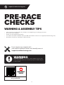
WARNING & ASSEMBLY TIPS
• Please do not use power tools for assembly as over tightening can damage your frame.
• Do not force parts together.
• Avoid cross threading threaded items.
• If in doubt consult the installation video (see QR code below or contact us at support@nextlevelracing.com)
• Hand wash Seat Cover separately in cold water only.
PRE-RACE
CHECKS
WARNING
CHOKING HAZARD - Small parts not for children under 3 years
or any individuals who have a tendency to place inedible objects
in their mouths.
If you require any support with
your product please contact our friendly team at:
support@nextlevelracing.com
ASSEMBLY
VIDEO
bit.ly/nlrbuild

5
Video Instruction: bit.ly/nlrbuild
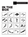
NOTE: Some Items Come with Rust Resistant Coating
IN THE
BOX
1 x LEFT PEDAL FRAME
1 x RIGHT SEAT FRAME
1 x CENTRE POLE BASE1 x REAR FRAME
1 x RIGHT PEDAL FRAME
1 x SEAT CROSS BRACE
1 x CENTRE POLE 1 x WHEEL PLATE
1 x PEDAL PLATE
1 x GO KART SEAT
1 X SEAT COVER
2 x FRAME BRACE
1 x CENTRE FRAME
1 x LEFT SEAT FRAME
1 x FRONT BUMPER
*NOT TO SCALE
1 x FRONT BUMPER MOUNT 1 x REAR BUMPER

6
support@nextlevelracing.com
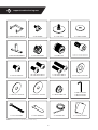
1 x BUTTKICKER MOUNT
30 x M8 16mm BOLTS
10 x M8 20mm BOLTS
8 x VELCRO TIES 3 x STICKER SHEETS
8 x CASTOR WHEEL
9 x FLAT FEET
2 x M8 30mm BOLTS
4 x M8 40mm BOLTS
1 x M10 ALLEN KEY
1 x M8 ALLEN KEY
1 x M6 ALLEN KEY
1 x REAR BUMPER MOUNT
2 x M8 12mm BOLTS 44 x M8 Ø20mm WASHERS
3 x M8 Ø30mm WASHERS 3 x M8 Ø35mm WASHERS
1 x 13mm SPANNER
4 x M8 KNOBS
8 x M8 20mm SOCKET HEAD BOLTS
1 x M10 20mm SOCKET HEAD BOLTS
4 x END CAPS
5 x FOOT SPACER
17 x M8 FLANGE NUT
1 x 14mm WRENCH
NOTE: Some Items Come with Rust Resistant Coating.

7
Video Instruction: bit.ly/nlrbuild
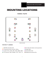
MOUNTING LOCATIONS
WHEEL PLATE
PRODUCT LEGEND:
*NOT TO SCALE*
MOZA R5 / R9 / R16 / R21 Simucube (with bottom mounting bracket)
Fanatec DD1 / DD2 / CSL DD / DD Pro Simagic Alpha
Logitech G Pro / G25 / G27 / G29 / G902 / G923 Nintendo Mario Kart
Thrustmaster T-818 / T500 RS / TGT / TSPC / TX SimXperience Accuforce Pro

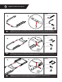
PARTS:
• • 1 x Left Pedal Frame
• • 1 x Right Pedal Frame
• • 1 x M8 16mm Bolt
• • 1 x M8 Ø20mm Washer
PARTS:
• • 1 x Centre Frame
• • 4 x M8 16mm Bolts
• • 4 x M8 Ø20mm Washers
PARTS:
• • 1 x Rear Frame
• • 4 x M8 16mm Bolts
• • 4 x M8 Ø20mm Washers
8
support@nextlevelracing.com
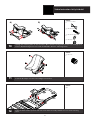
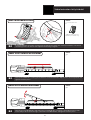
A) Align the nut inserts on the Centre Frame with the mounting holes on the Rear Frame.
B) Bolt through and secure with 4 x M8 Bolts and Washers.
02 A) Align the nut inserts on the Right and Left Pedal Frames with the mounting holes on the Centre
Frame. B) Bolt through and secure with 4 x M8 Bolts and Washers.
01
A) Align the nut inserts on the Right Pedal Frame with the mounting holes on the Left Pedal Frame.
B) Bolt through to the nut insert on the underside of frame and secure with 1 x M8 Bolt and Washer.
A) B)
B)
B)
A)
A)
03
Repeat
on Other
Side
Repeat
on Other
Side

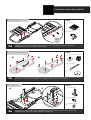
PARTS:
• • 1 x Pedal Plate
• • 4 x M8 Knobs
PARTS:
• • 1 x Centre Pole Base
• • 4 x M8 16mm Bolts
• • 4 x M8 Ø20mm vWashers
PARTS:
• • 9 x Flat Feet or 8 x Castor Wheels
or
• • 2 x Frame Braces
• • 5 x Foot Spacers
9
Video Instruction: bit.ly/nlrbuild
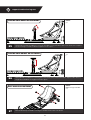
06
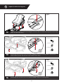
05 Flip the assembly upside down. A) Align 5 x Foot Spacers and 2 x Frame Braces with the footing mounts on the
bottom of the cockpit. B) Install 9 x Flat Feet or 8 x Castor Wheels into the mounting points.
A) Align the mounting holes on the Centre Pole Base with the nut inserts on the Centre Frame.
B) Bolt through and secure with 4 x M8 Bolts and Washers.
A) Align the nut inserts on the Pedal Plate with the slots on the Right and Left Pedal Frames.
B) Bolt through and secure with 4 x NLR Knobs.
NOTE: Flip the assembly upside down for easy installation.
If using Castor Wheels, leave middle rear mount empty.
NOTE: If using Load Cell Pedals, replace M8 Knobs with
M8 20mm Bolts and Washers supplied.
B)
B)
A)
A)
NOTE: Flip the assembly back
upright.
04
Repeat
on Other
Side

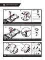
PARTS:
• • 1 x Centre Pole
• • 4 x M8 16mm Bolts
• • 4 x M8 Ø20mm Washers
• • Tip: If using high force feedback
wheelbase it is recommended to
use additional spare M8 16mm bolts
on Centre Pole (2x extra on each
side).
PARTS:
• • 1 x Wheel Plate
• • 4 x M8 16mm Bolts
• • 4 x M8 Ø20mm Washers
PARTS:
• • 1 x Go - Kart Seat
• • 1 x Left Seat Frame
• • 1 x Right Seat Frame
• • 2 x M8 30mm Bolts
• • 2 x M8 12mm Bolts
• • 4 x M8 Ø20mm Washers
• • 2 x M8 Ø30mm Washers
• • 2 x M8 Ø35mm Washers
10
support@nextlevelracing.com
07
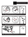
A) Align the nut inserts on the Centre Pole with the holes on the Centre Pole Base.
B) Bolt through and secure with 4 x M8 Bolts and Washers.
08 A) Align the mounting holes on the Wheel Plate with the nut inserts on the Centre Pole.
B) Bolt through and secure with 4 x M8 Bolts and Washers.
09 A) Align the mounting holes on the Left and Right Seat Frames with the nut inserts on the Go Kart Seat. Align 2 x Ø30mm and 2 x Ø35mm washers
in between Seat Frames and Seat. B) Bolt through and secure with 4 x M8 Bolts and Ø20mm Washers. (2 x 30mm Bolts for the upper mounts and 2
x 12mm Bolts for the lower mounts).
A)
A)
B)
B)
A) B)
M8 Ø30mm Washers
M8 Ø30mm Washers
M8 Ø35mm Washers
M8 Ø35mm Washers

PARTS:
• • 1 x Seat Cross Brace
• • 4 x M8 40mm Bolts
• • 4 x M8 Ø20mm Washers
• • 4 x M8 Flange Nuts
PARTS:
• • 4 x End Caps
PARTS:
• • NIL
11
Video Instruction: bit.ly/nlrbuild
10
A) Align the mounting holes on the Seat Cross Brace with the through holes on the Left and Right Seat
Frames. B) Bolt through and secure with 4 x M8 Bolts, Washers and Flange Nuts.
11 Install 4 x End Caps onto the Left and Right Seat Frames.
12 Pull Seat Slider Handle upwards and slide Seat Slider Assembly forward to access front mounting
holes.
A) B)

PARTS:
• • NIL
PARTS:
• • 2 x M8 20mm Bolts
• • 2 x M8 Ø20mm Washers
• • 2 x M8 Flange Nuts
PARTS:
• • 2 x M8 20mm Bolts
• • 2 x M8 Ø20mm Washers
• • 2 x M8 Flange Nuts
12
support@nextlevelracing.com
13 Align the mounting slots on the Left and Right Seat Frame with the middle mounting holes on the front
of the Seat Slider Assembly.
14 Bolt through the front holes and secure with 2 x M8 Bolts, Washers and Flange Nuts. Pull the Seat
Slider Handle upwards and slide the seat backwards when done.
15 Bolt through the rear holes and secure with 2 x M8 Bolts, Washers and Flange Nuts.
Repeat
on Other
Side
Repeat
on Other
Side

PARTS:
• • 1 x Front Bumper Mount
• • 3 x M8 16mm Bolts
• • 3 x M8 Ø20mm Washers
PARTS:
• • 1 x Front Bumper
• • 4 x M8 20mm Socket Head Bolts
• • 4 x M8 Flange Nut
PARTS:
• • 1 x Rear Bumper Mount
13
Video Instruction: bit.ly/nlrbuild
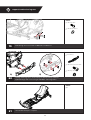
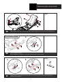
16 A) Align the Front Bumper Mount with the nut inserts on the front of the Pedal Frame.
B) Bolt through and secure with 3 x M8 Bolts and Washers.
17
A) Align the Front Bumper with mounting holes on Front Bumper Mount.
B) Bolt through and secure with 4 x M8 Bolts and Flange Nuts.
18 Align the Rear Bumper Mount with the nut inserts on the Rear Frame.
A) B)
A) B)
NOTE: If using Buttkicker refer to STEP 29.

PARTS:
• • 2 x M8 20mm Bolts
• • 2 x M8 Ø20mm Washers
PARTS:
• • 1 x Rear Bumper
• • 4 x M8 20mm Socket Head Bolts
• • 4 x M8 Flange Nuts
PARTS:
• • NIL
14
support@nextlevelracing.com
19 Bolt through and secure with 2 x M8 Bolts and Washers.
20 A) Align mounting holes on Rear Bumper with Rear Bumper Mount.
B) Bolt through and secure using 4 x M8 Bolts and Flange Nuts.
21 Your Go Kart Cockpit is complete.
A) B)

PARTS:
• • 1 x Go Kart Seat Cover
• • Tip: Hand wash Seat Cover
separately in cold water only
PARTS:
• • NIL
PARTS:
• • NIL
15
Video Instruction: bit.ly/nlrbuild
22 Install the Go Kart Seat Cover starting from the bottom first. Wrap the outer lip around the seat. Pinch
drawstring release on the back and pull the drawstring to tighten.
23
Loosen the NLR Knobs securing the Pedal Plate to the Pedal Frame. Adjust to the desired position and
tighten to lock in place.
24 Remove the front NLR Knobs and loosen the rear NLR Knobs securing the Pedal Plate to the Pedal
Frame. Adjust to the desired angle, reinstall the front NLR Knobs and tighten to lock in place.
SEAT COVER INSTALLATION
PEDAL PLATE LATERAL ADJUSTMENT
PEDAL PLATE ANGLE ADJUSTMENT

PARTS:
• • NIL
PARTS:
• • NIL
PARTS:
• • Tip: Use the edge of the 14mm
Wrench to help pry out the End
Caps.
16
support@nextlevelracing.com
25 Uninstall the rear Bolts and Washers, loosen the front Bolts securing the Wheel Plate to the Centre Pole. Adjust to
the desired angle, reinstall rear Bolts and tighten to lock in place.
26 Uninstall Bolts and Washers securing the Centre Pole to the Centre Pole Base. Adjust to the desired
height. Reinstall Bolts and tighten to lock in place.
27 Remove End Caps and Bolts securing the Go Kart Seat to the Seat Frame.
CENTRE POLE ANGLE ADJUSTMENT
CENTRE POLE HEIGHT ADJUSTMENT
SEAT ANGLE ADJUSTMENT

PARTS:
• • NIL
PARTS:
• • 1 x Buttkicker Mount
PARTS:
• • NIL
17
Video Instruction: bit.ly/nlrbuild
29 A) Uninstall Rear Bumper.
B) Uninstall Bolts and Washers securing Rear Bumper Mount to Rear Frame.
30 A) Align Buttkicker Mount with Rear Bumper Mount holes. Reinstall previously removed Bolts and Washers.
B) Reinstall Rear Bumper.
28 Adjust Go Kart Seat to the desired angle. Reinstall Bolts, tighten to lock in place. Reinstall End Caps.
A)
A)
B)
B)
BUTTKICKER MOUNT

WARNING
Please do not use power tools for assembly as over tightening can damage your frame.
Do not force parts together.
Avoid cross threading threaded items.
If in doubt consult the installation video (see QR code below or contact us at support@nextlevelracing.com).
Hand wash Seat Cover separately in cold water only.
NOTES
18
support@nextlevelracing.com
ASSISTANCE
ASSEMBLY
VIDEO
bit.ly/nlrbuild
If you require further support with your product please
contact our friendly team at: support@nextlevelracing.com

FR
GO KART Plus Manuel d’instructions
Nous savons que vous êtes impatient de commencer la course ! Prenez votre temps avec les instructions et suivez ce guide pour assembler votre produit. Vous vous préparerez au succès
en suivant le livret d’instructions pour optimiser pleinement votre produit.
VÉRIFICATIONS AVANT LA COURSE
AVERTISSEMENT
• Veuillez ne pas utiliser d’outils électriques pour l’assemblage car un serrage excessif peut endommager votre cadre.
• Ne forcez pas les pièces ensemble.
• Évitez de fausser le filetage des articles filetés.
• En cas de doute, consultez la vidéo d’installation (voir le code QR ci-dessous ou contactez-nous à support@nextlevelracing.com)
• Laver à la main la housse de siège séparément à l’eau froide uniquement.
Si vous avez besoin d’aide avec votre produit, veuillez contacter notre équipe amicale à : support@nextlevelracing.com
AVERTISSEMENT RISQUE D’ÉTOUFFEMENT
Petites pièces non destinées aux enfants de moins de 3 ans ou à toute personne ayant tendance à mettre des objets non comestibles dans sa bouche.
COMMENCER
01 – Reportez-vous à l’image. A) Alignez les inserts d’écrou sur le cadre de la pédale droite avec les trous de montage sur le cadre de la pédale gauche. B) Boulonnez à travers l’insert
d’écrou sur le dessous du cadre et fixez avec 1 boulon et rondelle M8.
02 – Reportez-vous à l’image. A) Alignez les inserts d’écrou sur les cadres de pédale droit et gauche avec les trous de montage sur le cadre central. B) Boulonnez et fixez avec 4 boulons et
rondelles M8.
03 – Reportez-vous à l’image. A) Alignez les inserts d’écrou sur le cadre central avec les trous de montage sur le cadre arrière. B) Boulonnez et fixez avec 4 boulons et rondelles M8.
04 – Reportez-vous à l’image. A) Alignez les inserts d’écrou sur la plaque de pédale avec les fentes sur les cadres de pédale droit et gauche. B) Boulonnez et fixez avec 4 boutons NLR.
05 – Reportez-vous à l’image. Retournez l’assemblage à l’envers. A) Alignez 5 x entretoises de pied et 2 x entretoises de cadre avec les supports de pied au bas du cockpit. B) Installez 9
pieds plats ou 8 roues pivotantes dans les points de montage.
06 – Reportez-vous à l’image. A) Alignez les trous de montage sur la base du poteau central avec les inserts d’écrou sur le cadre central. B) Boulonnez et fixez avec 4 boulons et rondelles
M8.
07 – Reportez-vous à l’image. A) Alignez les inserts d’écrou sur le poteau central avec les trous sur la base du poteau central. B) Boulonnez et fixez avec 4 boulons et rondelles M8.
08 – Reportez-vous à l’image. A) Alignez les trous de montage sur la plaque de roue avec les inserts d’écrou sur le poteau central. B) Boulonnez et fixez avec 4 boulons et rondelles M8.
09 – Reportez-vous à l’image. A) Alignez les trous de montage sur les cadres de siège gauche et droit avec les inserts d’écrou sur le siège de kart. Alignez 2 rondelles de Ø30 mm et 2
rondelles de Ø35 mm entre les cadres du siège et le siège. B) Boulonnez et fixez avec 4 boulons M8 et des rondelles Ø20 mm. (2 boulons de 30 mm pour les supports supérieurs et 2
boulons de 12 mm pour les supports inférieurs).
10 – Reportez-vous à l’image. A) Alignez les trous de montage sur le croisillon du siège avec les trous traversants sur les cadres de siège gauche et droit. B) Boulonnez et fixez avec 4
boulons M8, rondelles et écrous à embase.
11 – Reportez-vous à l’image. Installez 4 embouts sur les cadres de siège gauche et droit.
12 – Reportez-vous à l’image. Tirez la poignée de la glissière du siège vers le haut et faites glisser l’ensemble de la glissière du siège vers l’avant pour accéder aux trous de montage avant.
13 – Reportez-vous à l’image. Alignez les fentes de montage sur le cadre de siège gauche et droit avec les trous de montage du milieu à l’avant de l’ensemble de glissière de siège.
14 – Reportez-vous à l’image. Boulonnez à travers les trous avant et fixez avec 2 boulons M8, rondelles et écrous à embase. Tirez la poignée coulissante du siège vers le haut et faites
glisser le siège vers l’arrière lorsque vous avez terminé.
15 – Reportez-vous à l’image. Boulonnez à travers les trous arrière et fixez avec 2 boulons M8, rondelles et écrous à embase.
16 – Reportez-vous à l’image. A) Alignez le support de pare-chocs avant avec les inserts d’écrou à l’avant du cadre de pédale. B) Boulonnez et fixez avec 3 boulons et rondelles M8.
17 – Reportez-vous à l’image. A) Alignez le pare-chocs avant avec les trous de montage sur le support de pare-chocs avant. B) Boulonnez et fixez avec 4 boulons M8 et écrous à embase.
18 – Reportez-vous à l’image. Alignez le support de pare-chocs arrière avec les inserts d’écrou sur le cadre arrière.
19 – Reportez-vous à l’image. Boulonnez et fixez avec 2 boulons et rondelles M8.
20 – Reportez-vous à l’image. A) Alignez les trous de montage du pare-chocs arrière avec le support de pare-chocs arrière. B) Boulonnez et fixez à l’aide de 4 boulons M8 et d’écrous à
embase.
21 – Reportez-vous à l’image. Votre Cockpit Go Kart est terminé.
22 – Reportez-vous à l’image. Installez la housse de siège Go Kart en commençant par le bas. Enroulez la lèvre extérieure autour du siège. Pincez le cordon de serrage à l’arrière et tirez sur
le cordon pour le serrer.
23 – Reportez-vous à l’image. Desserrez les boutons NLR fixant la plaque de pédale au cadre de pédale. Ajustez à la position désirée et serrez pour verrouiller en place.
24 – Reportez-vous à l’image. Retirez les boutons NLR avant et desserrez les boutons NLR arrière fixant la plaque de pédale au cadre de pédale. Ajustez à l’angle désiré, réinstallez les
boutons NLR avant et serrez pour verrouiller en place.
25 – Reportez-vous à l’image. Désinstallez les boulons et les rondelles arrière, desserrez les boulons avant fixant la plaque de roue au poteau central. Ajustez à l’angle désiré, réinstallez les
boulons arrière et serrez pour verrouiller en place.
26 – Reportez-vous à l’image. Désinstallez les boulons et les rondelles fixant le poteau central à la base du poteau central. Ajustez à la hauteur désirée. Réinstallez les boulons et serrez
pour verrouiller en place.
27 – Reportez-vous à l’image. Retirez les embouts et les boulons fixant le siège de kart au cadre du siège.
28 – Reportez-vous à l’image. Ajustez le siège Go Kart à l’angle souhaité. Réinstallez les boulons, serrez pour verrouiller en place. Réinstallez les embouts.
29 – Reportez-vous à l’image. A) Désinstallez le pare-chocs arrière. B) Désinstallez les boulons et les rondelles fixant le support de pare-chocs arrière au cadre arrière.
30 – Reportez-vous à l’image. A) Alignez le support Buttkicker avec les trous du support de pare-chocs arrière. Réinstallez les boulons et les rondelles précédemment retirés. B) Réinstallez
le pare-chocs arrière.
AVERTISSEMENT
• Veuillez ne pas utiliser d’outils électriques pour l’assemblage car un serrage excessif peut endommager votre cadre.
• Ne forcez pas les pièces ensemble.
• Évitez de fausser le filetage des articles filetés.
• En cas de doute, consultez la vidéo d’installation (voir le code QR ci-dessous ou contactez-nous à support@nextlevelracing.com)
• Laver à la main la housse de siège séparément à l’eau froide uniquement.
19
Video Instruction: bit.ly/nlrbuild

NL
GO KART Plus-instructiehandleiding
We weten dat je staat te popelen om te gaan racen! Neem de tijd met de instructies en volg deze handleiding om uw product in elkaar te zetten. U bereidt uzelf voor op succes door het
instructieboekje te volgen om uw product volledig te optimaliseren.
CONTROLES VOOR DE RACE
WAARSCHUWING
• Gebruik geen elektrisch gereedschap voor de montage aangezien te vast aandraaien uw frame kan beschadigen.
• Forceer geen onderdelen in elkaar.
• Vermijd het kruiselings inrijgen van items met schroefdraad.
• Raadpleeg bij twijfel de installatievideo (zie QR-code hieronder of neem contact met ons op via support@nextlevelracing.com)
• Was de stoelbekleding apart met de hand in koud water.
Als u ondersteuning nodig heeft met uw product, neem dan contact op met ons vriendelijke team via: support@nextlevelracing.com
WAARSCHUWING VERSTIKKINGSGEVAAR
Kleine onderdelen niet voor kinderen jonger dan 3 jaar of personen die de neiging hebben om oneetbare voorwerpen in hun mond te stoppen.
BEGIN
01 – Zie aeelding. A) Lijn de moerinzetstukken op het rechter pedaalframe uit met de montagegaten in het linker pedaalframe. B) Bout door het moerinzetstuk aan de onderkant van het
frame en zet vast met 1 x M8 bout en ring.
02 – Zie aeelding. A) Lijn de moerinzetstukken op het rechter en linker pedaalframe uit met de montagegaten in het middelste frame. B) Bout door en zet vast met 4 x M8 bouten en
ringen.
03 – Zie aeelding. A) Lijn de moerinzetstukken op het middelste frame uit met de montagegaten op het achterframe. B) Bout door en zet vast met 4 x M8 bouten en ringen.
04 – Zie aeelding. A) Lijn de moerinzetstukken op de pedaalplaat uit met de sleuven in het rechter en linker pedaalframe. B) Vastschroeven en vastzetten met 4 x NLR-knoppen.
05 – Zie aeelding. Draai het geheel ondersteboven. A) Lijn 5 x voetafstandhouders en 2 x framesteunen uit met de voetsteunen aan de onderkant van de cockpit. B) Installeer 9 x platte
voeten of 8 x zwenkwielen in de bevestigingspunten.
06 – Zie aeelding. A) Lijn de montagegaten op de middenpaalvoet uit met de moerinzetstukken op het middenframe. B) Bout door en zet vast met 4 x M8 bouten en ringen.
07 – Zie aeelding. A) Lijn de moerinzetstukken op de middelste paal uit met de gaten in de basis van de middelste paal. B) Bout door en zet vast met 4 x M8 bouten en ringen.
08 – Zie aeelding. A) Lijn de montagegaten op de wielplaat uit met de moerinzetstukken op de middelste paal. B) Bout door en zet vast met 4 x M8 bouten en ringen.
09 – Zie aeelding. A) Lijn de montagegaten op het linker- en rechterstoelframe uit met de moerinzetstukken op de Go Kart-stoel. Lijn 2 x Ø30 mm en 2 x Ø35 mm sluitringen uit tussen
de stoelframes en de stoel. B) Bout door en zet vast met 4 x M8 bouten en Ø20mm sluitringen. (2 x 30 mm bouten voor de bovenste bevestigingen en 2 x 12 mm bouten voor de onderste
bevestigingen).
10 – Zie aeelding. A) Lijn de montagegaten op de dwarsbeugel van de stoel uit met de doorlopende gaten in het linker en rechter stoelframe. B) Bout door en zet vast met 4 x M8 bouten,
ringen en flensmoeren.
11 – Zie aeelding. Installeer 4 x eindkappen op de linker en rechter stoelframes.
12 – Zie aeelding. Trek de hendel van de stoelschuif omhoog en schuif de stoelschuif naar voren om toegang te krijgen tot de montagegaten aan de voorkant.
13 – Zie aeelding. Lijn de montagesleuven op het linker en rechter stoelframe uit met de middelste montagegaten aan de voorkant van de stoelschuif.
14 – Zie aeelding. Bout door de voorste gaten en zet vast met 2 x M8 bouten, ringen en flensmoeren. Trek de stoelschuiendel omhoog en schuif de stoel naar achteren als u klaar bent.
15 – Zie aeelding. Bout door de achterste gaten en zet vast met 2 x M8 bouten, ringen en flensmoeren.
16 – Zie aeelding. A) Lijn de voorbumperbevestiging uit met de moerinzetstukken aan de voorkant van het pedaalframe. B) Bout door en zet vast met 3 x M8 bouten en ringen.
17 – Zie aeelding. A) Lijn de voorbumper uit met de montagegaten op de voorbumpersteun. B) Bout door en zet vast met 4 x M8 bouten en flensmoeren.
18 – Zie aeelding. Lijn de achterbumpersteun uit met de moerinzetstukken op het achterframe.
19 – Zie aeelding. Bout door en zet vast met 2 x M8 bouten en ringen.
20 – Zie aeelding. A) Lijn de montagegaten op de achterbumper uit met de achterbumperbevestiging. B) Doorboren en vastzetten met 4 x M8 bouten en flensmoeren.
21 – Zie aeelding. Je Go Kart Cockpit is compleet.
22 – Zie aeelding. Installeer de Go Kart Seat Cover, beginnend vanaf de onderkant eerst. Wikkel de buitenste lip rond de zitting. Knijp op de achterkant van het trekkoord en trek aan het
trekkoord om het strakker te maken.
23 – Zie aeelding. Draai de NLR-knoppen los waarmee de pedaalplaat aan het pedaalframe is bevestigd. Pas de gewenste positie aan en draai vast om op zijn plaats te vergrendelen.
24 – Zie aeelding. Verwijder de voorste NLR-knoppen en maak de achterste NLR-knoppen los waarmee de pedaalplaat aan het pedaalframe is bevestigd. Pas de gewenste hoek aan,
installeer de voorste NLR-knoppen opnieuw en draai ze vast om ze op hun plaats te vergrendelen.
25 – Zie aeelding. Verwijder de achterste bouten en ringen, draai de voorste bouten los waarmee de wielplaat aan de middenpaal is bevestigd. Pas de gewenste hoek aan, installeer de
achterste bouten opnieuw en draai ze vast om ze op hun plaats te vergrendelen.
26 – Zie aeelding. Verwijder de bouten en ringen waarmee de middelste paal aan de middelste paalbasis is bevestigd. Stel af op de gewenste hoogte. Plaats de bouten terug en draai ze
vast om ze op hun plaats te vergrendelen.
27 – Zie aeelding. Verwijder de eindkappen en bouten waarmee de Go Kart-stoel aan het frame van de stoel is bevestigd.
28 – Zie aeelding. Stel Go Kart Seat in op de gewenste hoek. Plaats de bouten terug, draai ze vast om ze op hun plaats te vergrendelen. Installeer de eindkappen opnieuw.
29 – Zie aeelding. A) Achterbumper verwijderen. B) Verwijder de bouten en ringen waarmee de achterbumperbevestiging aan het achterframe is bevestigd.
30 – Zie aeelding. A) Lijn de Buttkicker-montage uit met de gaten voor de montage van de achterbumper. Plaats eerder verwijderde bouten en ringen terug. B) Plaats de achterbumper
terug.
WAARSCHUWING
• Gebruik geen elektrisch gereedschap voor de montage aangezien te vast aandraaien uw frame kan beschadigen.
• Forceer geen onderdelen in elkaar.
• Vermijd het kruiselings inrijgen van items met schroefdraad.
• Raadpleeg bij twijfel de installatievideo (zie QR-code hieronder of neem contact met ons op via support@nextlevelracing.com)
• Was de stoelbekleding apart met de hand in koud water.
20
support@nextlevelracing.com
Sayfa yükleniyor...
Sayfa yükleniyor...
Sayfa yükleniyor...
Sayfa yükleniyor...
Sayfa yükleniyor...
Sayfa yükleniyor...
Sayfa yükleniyor...
Sayfa yükleniyor...
Sayfa yükleniyor...
Sayfa yükleniyor...
Sayfa yükleniyor...
Sayfa yükleniyor...
-
 1
1
-
 2
2
-
 3
3
-
 4
4
-
 5
5
-
 6
6
-
 7
7
-
 8
8
-
 9
9
-
 10
10
-
 11
11
-
 12
12
-
 13
13
-
 14
14
-
 15
15
-
 16
16
-
 17
17
-
 18
18
-
 19
19
-
 20
20
-
 21
21
-
 22
22
-
 23
23
-
 24
24
-
 25
25
-
 26
26
-
 27
27
-
 28
28
-
 29
29
-
 30
30
-
 31
31
-
 32
32


