
7/2010
ND 1300
QUADRA-CHEK
Software Version
2.1.x
Quick Reference Guide
Kurzanleitung
Guide de Démarrage rapide
Guida rapida
Guía rápida de referencia
Snabbreferensguide
Beknopte handleiding
Stručná referenční příručka
Guia de referência rápida
Krótka instrukcja
Краткое руководство
Hızlı Başvuru Kılavuzu
參

ND 1300 QUADRA-CHEK
Front panel
Rear panel with video and CNC options
Side panel
Rear panel with optical edge detector and CNC options

1
ND 1300 QUADRA-CHEK English
Setup
For detailed description and latest document version, see www.heidenhain.de
Before Power up
Electrical connection
Line voltage: 100 V~ to 240 V~
(–15 % to +10 %)
Line frequency: 43 Hz to 63 Hz
Line fuse: T1600 mA, 250 V
5 x 20 mm
Power connector wiring
L: Line voltage (brown)
N: Neutral (blue)
Earth ground (yellow/green)
Danger of electrical shock!
Do not open the enclosure.•
Never use 3-wire to 2-wire adapters •
or allow the ground connection to
the ND 1300 to be interrupted or
disconnected.
Caution
Changes to the power cable may be
made only by an electrical technician.
Caution
Do not connect encoders or other
equipment to the ND 1300 when the
power is on.
Safety Considerations
General accepted safety precautions
must be followed when operating the
ND 1300. Failure to observe these
precautions could result in damage to
the equipment, or injury to personnel.
It is understood that safety rules within
individual companies vary. If a confl ict
exists between the material contained
in this guide and the rules of a company
using this system, the more stringent
rules should take precedence.
Controls and Displays
A LCD screen
B
Command keys: Control
measurement
C
Numeric keypad: Enter numeric
data
D
Fast track keys: Programmable
for frequently used functions
E
Send key: Transmit
measurement data to PC,
USB printer or USB drive
F
LCD on/off key: Turn LCD on or
off or delete features from the
feature list.
Connections rear side
1 Power switch
2 Power connection with fuse
3
Ground (protective ground)
4
Encoder inputs, X, Y, Z axis for
linear encoders Q axis for rotary
encoder. Interface specifi ed at
the time of purchase.
5
RS-232-C interface for PC
connection. RS-232 cable must
not include crossovers.
6
Remote accessory interface
RJ-45 for optional foot switch
accessory.
7
CNC control outputs for CNC
motor amplifi er.
8 Unused
Connections for video option
9
Coaxial video input from NTSC
or PAL cameras.
10
Y/C video input from NTSC or
PAL cameras.
11
Lighting and zoom input/output
connector.
Connections for optical edge
option
12
Optical cable connector for
Comparator reference light
source
13
Optical cable connector for
comparator screen sensor
Connections side view
14
Audio out for 3,5 mm
headphone /speaker jack,
monaural, 8 Ohm
15
USB type A interface for printer
or data storage
16 Unused
Mounting
The ND 1300 is secured to the swivel
slots of the mounting stand or arm
mount by a shoulder screw, a cap
screw mount is shown with associated
washers.
Very important
Please note
For your information
DR. JOHANNES HEIDENHAIN GmbH
Dr.-Johannes-Heidenhain-Straße 5
83301 Traunreut, Germany
{ +49 8669 31-0
| +49 8669 5061
E-mail: [email protected]
www.heidenhain.de

2
Calibrate the touch screen4.
The touch screen should be calibrated
to respond correctly to each operator’s
fi nger tip size and pressure.
Touch the • MISCELLANEOUS setup
menu item and then touch the CAL
button.
Follow the instructions shown on the •
LCD screen.
Select the point entry type5.
Backward or forward annotation can be
used to collect data points. Backward
annotation allows the user to probe
any number of data points to measure
a feature. Forward annotation limits
the number of points to a required
minimum.
Touch the • MEASURE setup
menu item and then touch the
ANNOTATION fi eld to select
BACKWARD or FORWARD
annotation.
Confi gure encoders6.
Touch the • ENCODERS setup menu
item and then touch the AXIS fi eld to
select the desired encoder axis.
Enter all the required encoder •
parameters.
Calibrate analog encoders by touching •
the CAL button. TTL encoders do not
require calibration.
Repeat setup for all axes.•
Confi gure display formats7.
Touch the • DISPLAY setup menu item.
Enter the desired display resolutions •
and other parameters.
Setup for the video option
Select a video camera type1.
Touch the VED setup menu item and
then touch the CAMERA TYPE fi eld
to select the desired camera output
format.
Adjust light level2.
Press the • FINISH key to return to the
DRO screen.
Touch the • LIGHT tab to display the
light controls.
Touch the light level slider or enter •
a light level number to optimize the
video light level.
Setup
Initial setup for video and
edge options
Display the setup menu1.
Touch the • QUESTION
icon once, and then touch
the SETUP button twice
to display the SETUP
MENU.
Touch menu items to select them. •
Scroll the setup menu using the
ARROW buttons.
Select the language2.
Touch the LANGUAGES setup menu
item and then touch the desired
language.
Note:
When the language is changed, power
to the ND 1300 must be cycled off and
then back on.
Enter the Supervisor Password3.
Touch the • SUPERVISOR setup menu
item and then touch the PASSWORD
fi eld.
Enter the supervisor password.•
Initial power up
Press the • POWER SWITCH to power
the ND 1300. The startup screen is
displayed.
Press the • FINISH key to display the
current axis positions on the DRO
screen.
Software setup
The operating parameters of the
ND 1300 must be confi gured prior
to using it for the fi rst time, and any
time part measurement, reporting or
communication requirements change.
Settings will be retained until:
The data-backup battery is changed•
The data and settings are cleared•
Software upgrades are performed•
Caution
Setup parameters control the operation
of the ND 1300 and are password-
protected. Only qualifi ed personnel
should be given password access to
setup screens.
Video and Edge options
Setup is divided into sections that are:
Initial setup for video and edge •
options
Setup for video option only•
Setup for edge option only •
Final setup for video and edge options•
Setup steps should be performed in the
order presented.

3
Calibrate optical edge detection2.
Teaching the edge detector calibrates
it to correctly recognize dark to light
transitions. Perform a TEACH calibration
after each startup, when lighting
changes, when the part changes and
when the magnifi cation level changes.
Touch the • TEACH button.
Follow the instructions shown on the •
screen to complete the calibration.
Calibrate crosshair offset3.
Crosshair offset calibration compensates
for the location differences between the
center of the crosshairs and the edge
detector. Crosshair offset calibration is
only necessary when crosshairs and
edge detection will be used to probe
points on the same part.
Touch the • CROSS CAL button.
Follow the instructions shown on the •
screen to complete the calibration.
Final setup for video and edge
options
Calibrate error correction1.
Linear (LEC), segmented linear (SLEC)
and nonlinear (NLEC) error correction
methods can be used to compensate
for encoder and machine errors.
Refer to the ND 1300 User Guide for
instructions.
Calibrate stage squareness2.
This calibration is not necessary when
NLEC error correction is used.
Align the squareness calibration •
artifact to the reference axis.
Measure the artifact angle. Refer to •
the angle measurement instructions
later in this document if necessary.
Display the • SETUP MENU and then
touch the SQUARENESS menu item.
Enter the measured angle into the •
OBSERVED ANGLE fi eld and then
enter the certifi ed artifact angle into
the STANDARD ANGLE fi eld.
Press the • FINISH key to complete the
calibration.
Note:
Many more setup functions are available
beyond the minimum parameters
discussed here. Refer to the ND 1300
User Guide for detailed instructions.
Add camera magnifi cations3.
When video systems include more
than one magnifi cation, additional
magnifi cation positions must be added
and calibrated.
Return to the setup menu and touch •
the MAGNIFICATIONS menu item
to dsplay the MAGNIFICATIONS
SCREEN.
Touch the • NEW button to add a
new magnifi cation. A new BUTTON
LABEL number will be added. This
label will be available on the DRO
screen during measurements.
The • BUTTON LABEL can be changed
to any 3 character string. Touch the
BUTTON LABEL fi eld and enter a
new label if desired.
Calibrate magnifi cations4.
Use a circle calibration artifact to
calibrate magnifi cations.
Touch the • ID number in the
MAGNIFICATIONS setup screen
to show the desired magnifi cation
BUTTON LABEL.
Touch the • ARTIFACT DIAMETER fi eld
and enter the artifact diameter.
Touch the • TEACH button and follow
the instructions shown on the screen.
Repeat this process for all •
magnifi cations.
Calibrate camera skew5.
Touch the • VED setup menu item and
then touch the CAL button.
Follow the instructions shown on the •
screen.
Calibrate parcentric and parfocal 6.
alignment
This calibration eliminates X and Y
axis offset errors that can occur when
changing video magnifi cations. Use
a circle calibration artifact for this
calibration.
Touch the • MAGNIFICATIONS setup
menu item.
Touch the • MAGNIFICATION
icon to display the
magnifi cation choices, then
select the highest level of
magnifi cation.
Enter zeros for the • PARCENTRIC and
PARFOCAL OFFSETS.
Repeat to zero the offsets of all •
magnifi cations.
Select the highest level of •
magnifi cation again.
Measure the circle artifact and create •
a zero datum on the circle center
point. Refer to the descriptions of
circle measurement and zero datum
creation later in this document if
necessary.
Select the next lower level of •
magnifi cation and measure the
same circle artifact. Make a note of
the X, Y and Z positions shown in
the measurement results for this
magnifi cation.
Enter the X, Y and Z positions into the •
OFFSET fi elds for this magnifi cation.
Repeat this process to enter • OFFSET
values for all levels of magnifi cation.
Setup for the optical edge
option
Add comparator magnifi cations1.
When coparator systems include more
than one magnifi cation, additional
magnifi cation positions must be added.
Touch the • MAGNIFICATIONS menu
item to dsplay the MAGNIFICATIONS
SCREEN.
Touch the • NEW button to add a
new magnifi cation. A new BUTTON
LABEL number will be added. This
label will be available on the DRO
screen during measurements.
The • BUTTON LABEL can be changed
to any 3 character string. Touch the
BUTTON LABEL fi eld and enter a
new label if desired.
Setup

4
Setup for the CNC option
Motor direction and PID loop
parameters must be confi gured prior to
using the CNC option for the fi rst time,
and anytime changes are made to the
motors or encoders.
Caution:
CNC parameters must be confi gured
carefully by qualifi ed personnel.
Run away motors resulting from
confi guration errors can cause serious
equipment damage and severe personal
injury.
Refer to the ND 1300 User Guide for
detailed instructions.
Preparing to measure
Power up the ND 13001.
Check connections to the ND 1300.•
Press the • POWER SWITCH to power
the ND 1300. The DRO screen will be
displayed after system initialization.
Find machine zero (optional)2.
Move the stage to cross reference
marks or fi nd hard stops if your system
was set up to establish machine zero at
startup.
Note:
A repeatable machine zero is required
when SLEC or NLEC error correction
is used. Refer to the User’s Guide for
detailed information.
Select a unit of measure3.
Touch the UNIT OF MEASURE
icon to toggle between inches
and mm.
Video probe option
Part features can be probed using
crosshair, offset crosshair, single edge
and multiple edge video probes. Touch
the crosshairs on the video screen to
select a probe.
Crosshair:
Single points can be probed
manually or automatically.
Offset crosshair:
Crosshair lines include
3 pixel offsets for improved
visibility on certain part
features. Single points can
be probed manually or
automatically.
Single edge:
Crosshair with small circle
at the center for edge
detection. Single points
can be probed manually or
automatically.
Multiple edge:
Crosshair with two small
concentric circles at the
center for edge detection.
Multiple points can be
probed automatically.
Using the multiple edge probe, once the
points required to determine the feature
type are probed, a circle and arrow will
be displayed. Move the stage to position
the arrow in the circle and press the
ENTER key to complete probing.
Note:
Touching the crosshairs on the screen
also displays probe confi guration tools.
Refer to the ND 1300 User Guide for
details.
Probing with video
Feature points can be probed manually
or automatically:
Manual probing1.
Position the feature point under the •
probe and press the ENTER key.
When all points have been probed, •
press the FINISH key.
Automatic probing2.
Touch the • AUTO-ENTER function on
the video screen to toggle automatic
probing on.
Off On
Position the feature point under the •
probe. After a brief delay, the point
will be entered automatically.
Crosshair and single edge probes: •
When all points have been probed,
press the FINISH key.
Multiple edge probe: Probe until a •
green arrow and circle appear. Move
the green arrow into the circle and
press the ENTER key.
Edge detection probe option
Part features can be probed
using manual crosshairs,
automatic crosshairs, manual
edge detection or automatic
edge detection. Touch the
PROBE ICON to display the
probe choices shown below.
Probing with edge detection
Feature points can be probed manually
or automatically:
Crosshair:
Position the crosshairs over the
desired location and press the
ENTER key.
Automatic crosshair:
Move the stage to position the
crosshairs over the desired
location. After a short delay, the
point will be entered.
Manual edge detection:
Move the stage to move the
edge detector across the
desired dark to light transition
and then press the ENTER key.
Automatic edge detection:
Move the stage to move the
edge detector across the
desired dark to light transition.
The point will be entered.
Leveling and aligning the part
Perform level and skew alignments to
eliminate measurement errors resulting
from misaligned parts.
Align the part on the stage1.
Align the reference edge of the part to a
measurement axis.
Setup
Operation

5
Level the part2.
Touch the • MEASURE tab to display
the measure icons, and then touch
the blue SKEW/LEVEL icon to display
the SKEW and LEVEL icons.
Touch the • LEVEL icon,
probe a minimum of 3
points on the desired part
reference-plane surface
and then press the FINISH
key.
Perform a skew alignment3.
Touch the • MEASURE tab to display
the measure icons, and then touch
the SKEW/LEVEL icon
Touch the • SKEW icon, probe
a minimum of 2 points on
the reference edge and then
press the FINISH key.
Creating a zero datum
Probe, construct or create a reference •
point.
Press the • DRO button to
display the DRO screen.
Press the • ZERO buttons for each axis
on the DRO screen.
Presetting a datum
Probe, construct or create a reference •
point.
Display the • DRO screen, touch the
axis values shown and enter preset
values using the numeric keypad.
Measuring features
Features are measured by touching a
feature icon or the MEASURE MAGIC
icon in the MEASURE tab, probing
points and then pressing the ENTER and
FINISH keys.
Measure a point1.
Touch the POINT icon and probe
a point.
Measure a line2.
Touch the LINE icon and probe a
minimum of 2 points.
Measure a circle3.
Touch the CIRCLE icon and
probe a minimum of 3 points
in any order around the
circumference.
Measure an arc4.
Touch the CIRCLE icon once
to display the ARC icon, then
touch the ARC icon and probe
a minimum of 3 points in
sequence from beginning to end
of the arc.
Measure a slot5.
Touch the SLOT icon and
probe 5 points in the following
sequence:
Two points on a long side•
One point in the closest end•
One point in the center of the •
second long side
Last point on the remaining •
end
Points can be probed in
sequence in either direction.
Measure an angle6.
Touch the ANGLE icon and
probe a minimum of 2 points on
each of the two legs. Press the
FINISH key after each leg.
Measure a distance7.
Touch the DISTANCE icon and
probe 1 point on each end of the
distance.
Use Measure Magic8.
Touch the MEASURE MAGIC
icon and probe points on a
feature. The feature type will
be determined based on the
pattern and sequence of point
probing.
Creating Features
Features are created by selecting the
feature type to be created, entering the
required feature data and then pressing
the FINISH key.
Specify the feature type1.
Touch the MEASURE tab and then touch
a measure icon to specify the type of
feature to be created.
Enter the feature data2.
Touch the ENTER DATA icon
and then enter data into fi elds
shown on the screen.
Complete the creation3.
Press the FINISH key to complete
the feature creation. The new created
feature will be shown in the feature list.
Constructing Features
Features are constructed by selecting
the feature type to be constructed,
selecting the parent features and then
pressing the FINISH key.
Specify the feature type1.
Touch the MEASURE tab and then touch
a measure icon to specify the type of
feature to be constructed.
Select the parent features2.
Touch the desired parent features in the
feature list. Check marks will be shown
near the parent features.
Complete the construction3.
Press the FINISH key to complete the
construction. The new constructed
feature will be shown in the feature list.
Operation

6
Viewing measurement data
Probed data points with form errors
are viewed by selecting a feature in
the feature list and touching the VIEW
button.
Select a feature1.
Touch the desired feature in the feature
list.
Press the 2. VIEW button
Form errors are displayed as
lines extending from data
points to the feature. The
two greatest form errors are
shown in red.
Applying Tolerances
Tolerances are applied by selecting
a feature, touching the TOL button,
selecting a tolerance type and entering
tolerance data.
Select a feature1.
Touch the desired feature in the feature
list.
Press the 2. TOL button
Tolerance types are
displayed at the bottom
of the screen as tolerance
icons.
Select a tolerance3.
Touch a tolerance icon to select the
desired tolerance type and then touch
the word TOLERANCE at the top left
corner of the screen to select a specifi c
tolerance.
Enter tolerance data4.
Enter NOMINAL and TOLERANCE data
into data fi elds provided in the tolerance
screen.
View the result5.
Green squares near features in the
feature list indicate passed tolerances.
Red squares and outlined characters
on the DRO screen indicate failed
tolerances.
Programming
Programs are recorded sequences
of measurement and other operator
activities stored by the ND 1300 to
be played back later when inspecting
identical parts. This guide discusses
recording, running, saving, loading and
deleting programs.
Note:
Programs can also be copied and edited.
Refer to the User’s Guide for detailed
information.
Recording a program1.
Touch the • PROGRAM tab.
Touch the round red • RECORD icon.
Enter a program name and press the •
FINISH key to begin recording.
Perform part alignment, measurement •
and other steps as usual. Program
recording is indicated by a red
program tab.
To end recording, press the •
PROGRAM tab and then press the
square black STOP icon. The new
program will be stored.
Press the • FINISH key to end the
programming session and return to
the DRO.
Running a program2.
Touch the • PROGRAM tab.
Touch a program name.•
Press the black triangular • RUN icon.
The feature type and points probed
will be displayed as points are probed.
After establishing a datum, press the •
VIEW button to see point targeting
while points are probed.
The program will stop automatically •
when all program steps have been
played. A message box will be
displayed.
Touch the message box to end the •
programming session and return to
the DRO.
Saving programs
Programs can be saved to a USB drive.
Plug an empty USB drive into the USB •
port on the side of the ND 1300.
Touch the • PROGRAM tab and touch
the program name.
Touch the • COPY PROGRAM
icon.
Press the • FINISH key to return to the
DRO.
Loading programs
Programs can be loaded from a USB
drive.
Plug the USB drive into the USB port •
on the side of the ND 1300.
Touch the C: • DRIVE icon
to change drives. The A:
(USB) DRIVE icon and list of
programs stored on the USB
drive will be shown,
Touch the desired program •
name in the list and then
touch the LOAD PROGRAM
icon. The highlighted program
will be loaded to the local (C:)
drive.
Touch the • A: DRIVE icon. The
C: DRIVE will be shown with
the loaded program in the C:
DRIVE program list.
The loaded program can now be
selected and run.
Deleting a program3.
Touch the • PROGRAM tab.
Touch a program name.•
Press the • CANCEL key. The program
will be deleted.
Note:
Use caution when deleting programs,
and store a backup of the program fi rst.
Deleted programs cannot be restored.
Press the • FINISH key to end the
programming session and return to
the DRO.
Reporting Results
Reports of results can be sent to a USB
printer, USB fl ash drive or a PC. The
report type and destination are specifi ed
in the PRINT setup screen.
Note:
Refer to the ND 1300 user guide on our
web site at: www.heidenhain.de for
details.
Press the • SEND key to report
results.
Operation

1
ND 1300 QUADRA-CHEK Deutsch
Setup
Eine genaue Beschreibung und die neueste Version des Dokuments fi nden Sie unter www.heidenhain.de
Vor der Inbetriebnahme
Elektrischer Anschluss
Netzspannung: 100 V~ bis 240 V~
(–15% bis +10%)
Netzfrequenz: 43 Hz bis 63 Hz
Netzsicherung: T1600 mA, 250 V
5 x 20 mm
Anschluss des Netzsteckers
L: Phase (braun)
N: Nullleiter (blau)
Schutzleiter (gelb/grün)
Stromschlaggefahr!
Gerät nicht öffnen!•
Schutzleiter darf nie unterbrochen •
sein, auch nicht bei Anschluss über
Adapter.
Achtung
Änderungen am Netzkabel nur durch
Elektrotechniker!
Achtung
Keine Messsysteme oder andere Geräte
anschließen, während die ND 1300
eingeschaltet ist.
Sicherheitsvorkehrungen
Für den Betrieb der ND 1300
gelten die allgemein anerkannten
Sicherheitsvorschriften. Nichtbeachtung
dieser Sicherheitsvorschriften kann zu
Sach- oder Personenschäden führen.
Die Sicherheitsvorschriften können je
nach Unternehmen variieren. Im Falle
eines Konfl ikts zwischen dem Inhalt
dieser Kurzanleitung und den internen
Regelungen eines Unternehmens, in
dem dieses Gerät verwendet wird,
sollten die strengeren Regelungen
gelten.
Anzeige- und Bedienelemente
A LCD-Anzeige
B
Befehlstasten: Messungen
steuern
C
Zahlenblock: Eingabe von
Zahlen
D
Schnellzugriffstasten:
programmierbar für häufi g
genutzte Funktionen
E
Taste SENDEN: Messdaten an
einen PC, USB-Drucker oder
USB-Speichermedium senden
F
LCD Ein/Aus-Taste: LCD-
Anzeige ein-/ausschalten oder
Konturelement aus Liste löschen
Anschlüsse auf der
Geräterückseite
1 Netzschalter
2 Netzanschluss mit Sicherung
3 Erdungsanschluss
(Schutzerdung)
4
Messgeräte-Eingänge, X-, Y-,
Z-Achse für Längenmessgeräte,
Q-Achse für Drehgeber. Schnitt-
stelle wird beim Kauf spezifi ziert.
5
Schnittstelle V.24/RS-232-C für
PC-Anschluss. Kabel für V.24/
RS-232 darf keine gekreuzten
Adern haben.
6 Schnittstelle RJ-45 für
Fernbedienungselemente für
optionalen Fußschalter
7
CNC-Steuerungsausgänge für
CNC-Antriebsverstärker
8 Nicht belegt
Anschlüsse für Option Video
9
Koaxialer Videoeingang für PAL-
oder NTSC-Kameras
10
Y/C-Videoeingang für PAL- oder
NTSC-Kameras
11
Anschluss für Lichtsteuerung
und Zoom-Ansteuerung
Anschlüsse für Option
Optischer Kantensensor
12
Referenzlicht-Eingang für
Profi lprojektor-Lichtquelle
13
Sensorlicht-Eingang für
optischen Kantensensor
Anschlüsse auf der Seite
14
Audio-Ausgang für Kopfhörer
3,5 mm / Lautsprecherbuchse,
Einohr, 8 Ohm
15
USB-Schnittstelle, Typ A, für
Drucker oder Speichermedien
16 Nicht belegt
Montage
Die ND 1300 wird mit einer Passschrau-
be, einer Kopfschraube und passenden
Unterlegscheiben in den Schwenk-
schlitzen des Montagefußes oder -arms
befestigt.
unbedingt beachten
wichtig
informativ
DR. JOHANNES HEIDENHAIN GmbH
Dr.-Johannes-Heidenhain-Straße 5
83301 Traunreut, Germany
{ +49 8669 31-0
| +49 8669 5061
E-mail: [email protected]
www.heidenhain.de

2
Touchscreen kalibrieren4.
Die Touchscreen sollte kalibriert
werden, damit sie auf die Bedienung
mittels Fingerberührung korrekt reagiert.
Menüpunkt • VERSCHIEDENES im
Menü SETUP und dann KAL antippen.
Den Anweisungen auf dem • LCD-
Bildschirm folgen.
Art der Punktaufnahme wählen5.
Zur Erfassung von Messpunkten
kann eine freie oder feste Punktzahl
verwendet werden. Freie Punktzahl
ermöglicht die Aufnahme einer
beliebigen Anzahl von Punkten zur
Messung eines Konturelements. Feste
Punktzahl begrenzt die Anzahl der
Punkte auf das nötige Minimum.
Menüpunkt • MESSEN im Menü
SETUP und dann Feld MESSPUNKT
FEST/FREI zur Auswahl zwischen
FREI und FEST antippen.
Messsysteme konfi gurieren6.
Menüpunkt • MESSSYSTEME und
dann Feld ACHSE antippen, um
gewünschte Messsystem-Achse zu
wählen.
Alle erforderlichen Messsystem-•
Parameter eingeben.
Zur Kalibrierung analoger •
Messsysteme die Schaltfl äche KAL
antippen. Bei TTL-Messsystemen ist
eine Kalibrierung nicht notwendig.
Setup für alle Achsen wiederholen.•
Anzeigeformate konfi gurieren7.
Menüpunkt • DISPLAY im Menü Setup
antippen.
Anzeigeaufl ösungen und weitere •
Parameter eingeben.
Setup für Option Video
Videokamera-Typ wählen.1.
Menüpunkt VED und dann Feld
KAMERATYP antippen, um das
gewünschte Kamera-Ausgabeformat zu
wählen.
Beleuchtung einstellen2.
Taste • FINISH drücken, um
zur Anzeige ISTPOSITION
zurückzukehren.
Reiter • LICHT antippen, um
Lichtsteuerelemente anzuzeigen.
Mit Schieberegler oder durch •
Eingabe einer Lichtpegel-Nummer
die Ausleuchtung des Prüfl ings
optimieren.
Setup
Erst-Setup der Optionen Video
und Kantensensor
Menü Setup aufrufen.1.
Zum Aufrufen des •
Menüs SETUP das
FRAGEZEICHEN einmal
und dann SETUP zweimal
antippen.
Menüpunkte durch Antippen •
auswählen. Mit den PFEILTASTEN
durch das Menü Setup scrollen.
Sprache wählen2.
Menüpunkt SPRACHEN im Menü
Setup und dann gewünschte Sprache
antippen.
Hinweis:
Eine Änderung der Sprache wird erst
nach einem Neustart der ND 1300
wirksam.
Hinweis:
Die ND 1300 unterstützt die folgenden
Sprachen: Deutsch, Englisch,
Französisch, Italienisch, Japanisch,
Polnisch, Russisch, Spanisch,
Tschechisch, vereinfachtes und
traditionelles Chinesisch.
Administrator-Passwort eingeben3.
Menüpunkt • ADMINISTRATOR und
dann Feld PASSWORT antippen.
Passwort eingeben.•
Erstinbetriebnahme
Zum Einschalten der ND 1300 •
den NETZSCHALTER drücken.
Es erscheint der Startbildschirm.
Zur Anzeige der aktuellen •
Achspositionen Taste FINISH
drücken.
Software-Setup
Die Betriebsparameter der ND 1300
müssen vor der Erstinbetriebnahme und
immer, wenn sich die Anforderungen
an die Vermessung von Teilen,
Berichterstellung oder Kommunikation
ändern, konfi guriert werden.
Einstellungen werden beibehalten bis:
Batterie für Daten-Backup gewechselt •
wird.
Daten und Einstellungen gelöscht •
werden.
Software-Upgrades durchgeführt •
werden.
Achtung
Die Setup-Parameter steuern die
Bedienung der ND 1300 und sind
passwortgeschützt. Das Passwort
für die Setup-Menüs sollte nur an
qualifi zierte Personen weitergegeben
werden.
Optionen Video und
Kantensensor
Das Menü Setup ist in folgende
Bereiche unterteilt:
Erst-Setup der Optionen Video und •
Kantensensor
Setup der Option Video•
Setup der Option Kantensensor •
Abschluss-Setup der Optionen Video •
und Kantensensor
Die Setup-Schritte sollten in der
aufgeführten Reihenfolge durchgeführt
werden.

3
Optischen Kantensensor kalibrieren2.
Mit LERNEN den Kantensensor
kalibrieren, damit er Hell-Dunkel-
Übergänge richtig erkennt. Eine
Kalibrierung mit LERNEN immer
nach Systemstart durchführen, oder
wenn sich Beleuchtung, Teil oder
Vergrößerungsfaktor ändern.
Schaltfl äche • LERNEN antippen.
Für die Durchführung der Kalibrierung •
den Anweisungen auf dem Bildschirm
folgen.
Fadenkreuz-Offset kalibrieren3.
Die Kalibrierung des Fadenkreuz-Offsets
dient zur Kompensation des Offsets
zwischen Mittelpunkt des Fadenkreuzes
und Kantensensor. Die Kalibrierung des
Fadenkreuz-Offsets ist nur notwendig,
wenn zur Punktaufnahme am gleichen
Teil sowohl Fadenkreuz als auch
Kantensensor verwendet werden.
Schaltfl äche • FK-KAL. antippen.
Für die Durchführung der Kalibrierung •
den Anweisungen auf dem Bildschirm
folgen.
Abschluss-Setup der Optionen
Video und Kantensensor
Fehlerkorrektur kalibrieren1.
Zur Korrektur von Messsystem- und
Maschinenfehlern kann die lineare
(LEC), abschnittsweise lineare (SLEC)
und nichtlineare (NLEC) Fehlerkorrektur
verwendet werden. Siehe auch Geräte-
Handbuch ND 1300.
Rechtwinkligkeit kalibrieren2.
Diese Kalibrierung ist bei Verwendung
der NLEC-Fehlerkorrektur nicht nötig.
Messnormal für die Kalibrierung •
der Rechtwinkligkeit an der
Referenzachse ausrichten.
Normwinkel messen. Hinweise zur •
Messung von Winkeln fi nden Sie auf
den nachfolgenden Seiten.
Menü • SETUP aufrufen und dann
Menüpunkt RWK antippen.
Gemessenen Winkel in Feld •
GEMESSEN und zertifi zierten
Normwinkel in Feld NOMINAL
eingeben.
Taste • FINISH drücken, um die
Kalibrierung abzuschließen.
Hinweis:
Neben den hier beschriebenen
Mindestparametern gibt es noch viele
weitere Setup-Funktionen. Siehe auch
Geräte-Handbuch ND 1300.
Vergrößerungen hinzufügen3.
Bei Videosystemen mit mehr als einer
Vergrößerung müssen alle weiteren
Vergrößerungen hinzugefügt und
kalibriert werden.
Zum Menü Setup zurückkehren und •
Menüpunkt VERGRÖSSERUNG
antippen, um Untermenü
VERGRÖSSERUNG aufzurufen.
Mit Schaltfl äche • NEU eine neue
Vergrößerung hinzufügen. Eine neue
TASTEN-Nummer wird hinzugefügt.
Diese Tastenbezeichnung steht in der
Anzeige ISTPOSITION während der
Messungen zur Verfügung.
Die • TASTENBEZEICHNUNG besteht
aus max. 3 beliebigen Zeichen. Feld
TASTENBEZEICHNUNG antippen
und, falls gewünscht, eine neue
Bezeichnung eingeben.
Vergrößerungen kalibrieren4.
Zum Kalibrieren der Vergrößerungen
einen Normkreis verwenden.
ID• -Nummer in Fenster SETUP:
VERGRÖSSERUNG antippen, um
gewünschte TASTENBEZEICHNUNG
für Vergrößerung anzuzeigen.
Feld • DURCHMESSER DES
NORMALS antippen und
Durchmesser des Normals eingeben.
Schaltfl äche • LERNEN antippen und
Anweisungen auf dem Bildschirm
folgen.
Diese Vorgehensweise für alle •
Vergrößerungen wiederholen.
Kameraausrichtung kalibrieren5.
Menüpunkt • VED im Menü SETUP
und dann Schaltfl äche KAL antippen.
Anweisungen auf dem Bildschirm •
folgen.
Parzentrizität und Parfokalität 6.
kalibrieren
Diese Kalibrierung beseitigt Offset-
Fehler in X und Y, die zwischen
verschiedenen Vergrößerungen
auftreten. Für diese Kalibrierung einen
Normkreis verwenden.
Menüpunkt • VERGRÖSSERUNG im
Menü Setup antippen.
Taste für • VERGRÖSSERUNG
antippen, um mögliche
Vergrößerungen anzuzei-
gen. Höchste Vergrößerung
wählen.
Für • PARZENTRISCHEN und
PARFOKALEN OFFSET jeweils Null
eingeben.
Offsetwerte aller Vergrößerungen •
ebenfalls auf Null setzen.
Nochmals höchste Vergrößerung •
wählen.
Normkreis messen und Nullpunkt •
auf Kreismittelpunkt setzen. Das
Messen von Kreisen und Setzen des
Nullpunkts ist auf den nachfolgenden
Seiten beschrieben.
Nächstkleinere Vergrößerung •
wählen und Normkreis erneut
messen. Notieren Sie sich die im
Messergebnis angezeigten X-, Y- und
Z-Werte für diese Vergrößerung.
X-, Y- und Z- Positionen für diese •
Vergrößerung in jeweilige OFFSET-
Felder eintragen.
Diese Vorgehensweise wiederholen •
bis die OFFSET-Werte für alle
Vergrößerungen eingegeben sind.
Setup für Option Optischer
Kantensensor
Vergrößerungen des 1.
Profi lprojektors hinzufügen
Bei Projektoren mit mehr als einer
Vergrößerung müssen alle weiteren
Vergrößerungen hinzugefügt werden.
Menüpunkt • VERGRÖSSERUNG
antippen, um Untermenü
VERGRÖSSERUNG aufzurufen.
Mit Schaltfl äche • NEU eine neue
Vergrößerung hinzufügen. Eine neue
TASTEN-Nummer wird hinzugefügt.
Diese Tastenbezeichnung steht in der
Anzeige ISTPOSITION während der
Messungen zur Verfügung.
Die • TASTENBEZEICHNUNG besteht
aus max. 3 beliebigen Zeichen. Feld
TASTENBEZEICHNUNG antippen
und, falls gewünscht, eine neue
Bezeichnung eingeben.
Setup

4
Setup für Option CNC
Die Richtung des Antriebs und die PID-
Reglerparameter müssen vor der ersten
Verwendung der Option CNC, und
immer wenn Änderungen an Antrieb
oder Messsystemen vorgenommen
werden, konfi guriert werden.
Achtung:
CNC-Parameter dürfen nur von qualifi -
zierten Personen und mit großer Sorgfalt
konfi guriert werden. Konfi gurationsfeh-
ler, die zu unkontrolliertem Motorverhal-
ten führen, können schwere Sach- oder
Personenschäden verursachen.
Siehe auch Geräte-Handbuch ND 1300.
Messung vorbereiten
ND 1300 einschalten1.
Anschlüsse der ND 1300 überprüfen.•
Mit dem • NETZSCHALTER die
ND 1300 einschalten. Die DRO-
Anzeige erscheint nach der
Systeminitialisierung.
Maschinen-Nullpunkt ermitteln 2.
(optional)
Tisch verfahren, um Referenzmarken zu
überfahren oder Anschläge zu fi nden,
wenn das System so eingerichtet
ist, dass beim Start ein Maschinen-
Nullpunkt ermittelt wird.
Hinweis:
Bei Verwendung der Fehlerkorrektur
SLEC oder NLEC ist ein reproduzierbarer
Maschinen-Nullpunkt erforderlich. Siehe
auch Geräte-Handbuch.
Maßeinheit wählen3.
Symbol MASSEINHEIT
antippen, um zwischen Zoll und
Millimeter umzuschalten.
1-Punkt-Werkzeug:
Fadenkreuz mit kleinem
Kreis in der Mitte zur
Kantenerkennung. Einzelne
Punkte können manuell
oder automatisch erfasst
werden.
Multipunkt-Werkzeug:
Fadenkreuz mit zwei
kleinen konzentrischen
Kreisen in der Mitte zur
Kantenerkennung. Mehrere
Punkte können automatisch
erfasst werden.
Beim Multipunkt-Werkzeug erscheinen
ein Kreis und ein Pfeil, sobald die
zur Bestimmung des Elements
erforderlichen Punkte erfasst sind. Tisch
so verfahren, dass sich die Pfeilspitze
im Zielkreis befi ndet und mit ENTER die
Punktaufnahme abschließen.
Hinweis:
Das Fenster, das nach Antippen des
Fadenkreuzes erscheint, enthält auch
Optionen zur Werkzeugkonfi guration.
Siehe auch Geräte-Handbuch ND 1300.
Punktaufnahme mit Video-
Option
Messpunkte können manuell oder
automatisch erfasst werden:
Manuelle Punktaufnahme1.
Messpunkt des Elements unter •
Werkzeug platzieren und ENTER
drücken.
Sobald alle Punkte erfasst wurden, •
Taste FINISH drücken.
Automatische Punktaufnahme2.
Funktion • AUTO-EINGABE antippen,
um automatische Punktaufnahme zu
aktivieren.
Aus Ein
Messpunkt des Elements unter •
Werkzeug platzieren. Nach kurzer
Wartezeit wird der Messpunkt
automatisch eingetragen.
Fadenkreuz- und 1-Punkt-Werkzeug: •
Sobald alle Punkte erfasst wurden,
Taste FINISH drücken.
Multipunkt-Werkzeug: Punkte •
aufnehmen bis grüner Pfeil und Kreis
erscheinen. Tisch verfahren, bis sich
Pfeilspitze im Zielkreis befi ndet und
ENTER drücken.
Option Kantensensor
Messpunkte können sowohl
mit Fadenkreuz als auch
Kantensensor manuell oder
automatisch erfasst werden.
Symbol für PUNKTAUFNAHME
antippen, um die nachfolgenden
Antastfunktionen anzuzeigen.
Punktaufnahme mittels
Kantenerkennung
Messpunkte können manuell oder
automatisch erfasst werden:
Fadenkreuz:
Fadenkreuz über gewünschtem
Punkt platzieren und ENTER
drücken.
Automatisches Fadenkreuz:
Tisch so verschieben, dass sich
Fadenkreuz über gewünschtem
Punkt befi ndet. Nach kurzer
Wartezeit wird der Punkt
automatisch eingetragen.
Manuelle Kantenerkennung:
Tisch mit Kantensensor über
den gewünschten Hell-Dunkel-
Übergang bewegen und ENTER
drücken.
Automatische
Kantenerkennung:
Tisch mit Kantensensor über
den gewünschten Hell-Dunkel-
Übergang bewegen. Der Punkt
wird eingetragen.
Teil ausrichten und
Bezugsebene ermitteln
Die Teileausrichtung und Ermittlung der
Bezugsebene dient zur Vermeidung
von Messfehlern aufgrund falsch
ausgerichteter Teile.
Teil auf dem Tisch ausrichten1.
Referenzkante des Teils an einer
Messachse ausrichten.
Bezugsebene des Teils ermitteln2.
Mit Reiter • MESSEN die Messsymbole
aufrufen. Dann mit blauem Symbol
für AUSRICHTUNG/EBENE die
Symbole für AUSRICHTUNG und
BEZUGSEBENE anzeigen.
Setup
Bedienung
Option Video
Messpunkte können mit Fadenkreuz,
Offset-Fadenkreuz, 1-Punkt- oder
Multipunkt-Werkzeug erfasst werden.
Fadenkreuz auf dem Bildschirm
antippen, um ein Werkzeug zu wählen.
Fadenkreuz:
Einzelne Punkte können
manuell oder automatisch
erfasst werden.
Offset-Fadenkreuz:
Die Fadenkreuzlinien haben
einen Offset von 3 Pixeln,
damit bestimmte Elemente
besser sichtbar sind.
Einzelne Punkte können
manuell oder automatisch
erfasst werden.

5
Symbol für • BEZUGSEBENE
antippen, an gewünschter
Bezugsebene des Teils
mindestens drei Punkte
aufnehmen und FINISH
drücken.
Teileausrichtung durchführen3.
Mit Reiter • MESSEN die
Messsymbole aufrufen. Dann Symbol
für AUSRICHTUNG/EBENE antippen.
Symbol für • BEZUGSEBENE
antippen, an Bezugskante
mindestens zwei Punkte
aufnehmen und dann
FINISH drücken.
Nullpunkt festlegen
Bezugspunkt aufnehmen, •
konstruieren oder defi nieren.
Mit • XYZ-ANZEIGE die
ANZEIGE ISTPOSITION
aufrufen.
Jede Achse in der Anzeige •
ISTPOSITION mit der Schaltfl äche
NULLEN auf Null setzen.
Wert für Bezugspunkt setzen
Bezugspunkt aufnehmen, •
konstruieren oder defi nieren.
Anzeige ISTPOSITION aufrufen, •
angezeigte Achswerte antippen und
mit numerischen Tasten gewünschte
Werte eingeben.
Konturelemente messen
Zum Messen von Elementen ein Ele-
ment-Symbol oder Symbol MEASURE
MAGIC auf Reiter MESSEN antippen,
Punkte aufnehmen, mit ENTER bestäti-
gen und mit FINISH beenden.
Punkt messen1.
PUNKT-Symbol antippen und
einen Punkt aufnehmen.
Gerade messen2.
GERADE-Symbol antippen
und mindestens 2 Punkte
aufnehmen.
Kreis messen3.
KREIS-Symbol antippen und
mindestens 3 Punkte auf
Kreisumfang in beliebiger
Reihenfolge aufnehmen.
Kreisbogen messen4.
Durch einmaliges Antippen
des KREIS-Symbols das
KREISBOGEN-Symbol aufrufen,
KREISBOGEN-Symbol einmal
antippen und mindestens
3 Punkte nacheinander
von Anfang bis Ende des
Kreisbogens aufnehmen.
Nut messen5.
NUT-Symbol antippen
und 5 Punkte in folgender
Reihenfolge aufnehmen:
2 Punkte an einer langen •
Seite
1 Punkt an der •
nächstgelegenen kurzen Seite
1 Punkt in der Mitte der •
zweiten langen Seite
Letzten Punkt an der übrigen •
kurzen Seite
Die Punkte können
nacheinander in beliebiger
Richtung aufgenommen
werden.
Winkel messen6.
WINKEL-Symbol antippen
und mindestens 2 Punkte an
jedem der beiden Schenkel
aufnehmen. Nach jedem
Schenkel die Taste FINISH
drücken.
Abstand messen7.
ABSTAND-Symbol antippen und
jeweils 1 Punkt an beiden Enden
der Strecke aufnehmen.
Measure Magic verwenden8.
MEASURE MAGIC -Symbol
antippen und Punkte eines
Elements aufnehmen.
Elementtyp wird aufgrund der
Verteilung und Reihenfolge der
erfassten Punkte berechnet.
Konturelemente defi nieren
Konturelemente werden durch Auswahl
des gewünschten Konturelement-
Typs und Eingabe der erforderlichen
Konturelement-Daten defi niert. Die
Defi nition wird mit der Taste FINISH
bestätigt.
Konturelement-Typ festlegen1.
Reiter MESSEN und dann ein
Messsymbol antippen, um Element-Typ
zu wählen, der defi niert werden soll.
Konturelement-Daten 2.
eingeben
Symbol für DATEN-EINGABE
antippen und Daten in die am
Bildschirm angezeigten Felder
eintragen.
Defi nition abschließen3.
Taste FINISH drücken, um die Defi nition
eines Konturelements abzuschließen.
Ein neu defi niertes Konturelement wird
in der Elementliste angezeigt.
Konturelemente konstruieren
Zur Konstruktion von Konturelementen
zuerst den gewünschten Element-
Typ, dann die dafür nötigen, bereits
gemessenen Bezugselemente wählen
und mit Taste FINISH bestätigen.
Konturelement-Typ festlegen1.
Reiter MESSEN und dann ein
Messsymbol antippen, um Element-Typ
zu wählen, der konstruiert werden soll.
Bezugselemente wählen2.
Gewünschte Bezugselemente in
der Elementliste wählen. Diese
Bezugselemente werden mit einem
Häkchen versehen.
Konstruktion abschließen3.
Taste FINISH drücken, um die
Konstruktion fertigzustellen. Ein neu
konstruiertes Konturelement wird in der
Elementliste angezeigt.
Bedienung

6
Messdaten anzeigen
Konturelement in der Elementliste wäh-
len und ANSICHT antippen, um Mes-
spunkte mit Formfehlern anzuzeigen.
Konturelement wählen1.
Gewünschtes Konturelement in der
Elementliste antippen.
ANSICHT2. antippen
Formfehler werden als
Linien dargestellt, die
von Datenpunkten zum
Konturelement laufen. Die
zwei größten Formfehler
sind rot markiert.
Toleranzprüfung
Zur Prüfung von Toleranzen ein
Konturelement wählen, die Schaltfl äche
TOL antippen, eine Toleranzart wählen
und die Toleranzdaten eingeben.
Konturelement wählen1.
Gewünschtes Konturelement in der
Elementliste antippen.
TOL2. antippen
Die Toleranzarten werden
unten am Bildschirm in Form
von Symbolen angezeigt.
Toleranz wählen3.
Ein Toleranz-Symbol antippen, um die
gewünschte Toleranzart zu wählen und
dann das im Toleranzfenster oben links
angezeigte Wort TOLERANZ: ... antippen,
um eine spezielle Toleranz zu wählen.
Toleranzdaten eingeben4.
Den SOLLWERT und die TOLERANZ-
DATEN in die entsprechenden Felder im
Toleranzfenster eingeben.
Ergebnis anzeigen5.
War die Toleranzprüfung in Ordnung, so
werden die Elemente mit einem grünen
Rechteck in der Elementliste versehen.
War die Messung außerhalb der Toleranz,
ist das Rechteck rot und die Zeichen
werden in Konturschrift dargestellt.
Programmieren
Programme sind aufgenommene
Messfolgen und andere, vom Bediener
gedrückte Tastenfolgen, die von der
ND 1300 zum späteren Abspielen bei
der Prüfung identischer Teile gespeichert
werden. Die Aufnahme, das Ausführen,
Speichern, Laden und Löschen von
Programmen wird in dieser Anleitung
erklärt.
Hinweis:
Programme können auch kopiert und
bearbeitet werden. Siehe auch Geräte-
Handbuch.
Programme aufnehmen1.
Reiter • PROGRAMM antippen.
Das runde rote Symbol für •
AUFNAHME antippen.
Programmnamen eingeben und mit •
FINISH die Aufnahme starten.
Teileausrichtung, Messung und •
weitere Schritte wie gewohnt
durchführen. Der Reiter
PROGRAMM wird während der
Programmaufnahme in roter Schrift
dargestellt.
Durch Antippen des Reiters •
PROGRAMM die Aufnahme beenden
und dann das rechteckige schwarze
STOPP-Symbol antippen. Ein neues
Programm wird gespeichert.
Mit • FINISH den Programmmodus
beenden und zur Anzeige
ISTPOSITION zurückkehren.
Programm ausführen2.
Reiter • PROGRAMM antippen.
Programmnamen wählen.•
Das schwarze dreieckige Symbol •
für AUSFÜHREN antippen. Der
Konturelement-Typ und die erfassten
Punkte werden während der
Punktaufnahme angezeigt.
Nach Setzen des Teile-Nullpunkts die •
Schaltfl äche ANSICHT antippen, um
während der Punktaufnahme mittels
Pfeil zur Messposition geführt zu
werden.
Das Programm stoppt automatisch, •
wenn alle Programmschritte
ausgeführt wurden. Ein
Hinweisfenster erscheint.
Hinweisfenster antippen, um •
Programmmodus zu beenden
und zur Anzeige ISTPOSITION
zurückzukehren.
Programme speichern
Programme können auf einem USB-
Speichermedium gespeichert werden.
Ein leeres USB-Speichermedium an •
den USB-Anschluss an der Seite der
ND 1300 anschließen.
Reiter • PROGRAMM und dann
Programmnamen antippen.
Symbol für • PROGRAMM
KOPIEREN antippen.
Taste • FINISH drücken, um
zur Anzeige ISTPOSITION
zurückzukehren.
Programme importieren
Programme können von einem USB-
Speichermedium importiert werden.
Das USB-Speichermedium an den •
USB-Anschluss an der Seite der
ND 1300 anschließen.
Symbol C: • LAUFWERK
antippen, um Laufwerk
zu wechseln. Das Symbol
A: (USB) LAUFWERK und
die auf dem USB-Medium
gespeicherten Programme
werden angezeigt.
Gewünschten •
Programmnamen in der
Liste und dann Symbol
für PROGRAMM LADEN
antippen. Das gewählte
Programm wird auf das lokale
Laufwerk (C:) geladen.
Symbol für • A: LAUFWERK
antippen. Das LAUFWERK C:,
dessen Programmliste jetzt
das importierte Programm
enthält, wird angezeigt.
Das importierte Programm kann jetzt
angewählt und ausgeführt werden.
Programm löschen3.
Reiter • PROGRAMM antippen.
Programmnamen wählen.•
Taste • CANCEL drücken. Das
Programm wird gelöscht.
Hinweis:
Beim Löschen von Programmen
sollte vorsichtshalber zuerst eine
Sicherungskopie des Programms
angelegt werden. Einmal gelöschte
Programme können nicht
wiederhergestellt werden.
Mit • FINISH den Programmmodus
beenden und zur Anzeige
ISTPOSITION zurückkehren.
Ergebnisberichte
Ergebnisberichte können an einen USB-
Drucker, USB-Speicher oder einen PC
gesendet werden. Die Art des Berichts
und der Empfänger werden im Setup-
Untermenü DRUCKEN defi niert.
Hinweis:
Ausführlichere Erläuterungen
fi nden Sie im Geräte-Handbuch
ND 1300 auf unserer Website unter
www.heidenhain.de.
Taste • SENDEN drücken, um
Ergebnisberichte zu erstellen.
Bedienung

1
ND 1300 QUADRA-CHEK Français
Paramétrage
Pour une description détaillée et la version la plus récente du document, voir www.heidenhain.fr
Avant la mise sous tension
Raccordement électrique
Tension secteur : 100 V~ à 240 V~
(–15 % à +10 %)
Fréquence secteur : 43 Hz to 63 Hz
Fusible : T1600 mA, 250 V
5 x 20 mm
Câblage de la prise secteur
L : Ligne de phase (brun)
N : Neutre (bleu)
Terre (jaune/vert)
Danger de choc électrique!
Ne pas ouvrir le boîtier.•
Ne jamais utiliser un adaptateur •
3 fi ls/2 fi ls, ou ne pas utiliser avec une
ligne de terre interrompue ou non
raccordée au ND 1300.
Attention
Le câble d'alimentation ne doit être
changé que par un électricien..
Attention
Ne pas connecter les encodeurs ou
autres équipements lorsque le ND 1300
est sous tension.
Consignes de sécurité
Les consignes des sécurité doivent
être respectées lors de l'utilisation
du ND 1300. La non observation de
ces consignes peut occasionner des
dommages à l'appareil ou blesser
l'opérateur. Bien entendu, les règles
de sécurité varient en fonction des
entreprises. Si l'appareil ne devait
pas correspondre pas aux normes de
sécurité de l'entreprise, il faudrait tenir
compte en priorité des règles les plus
astreignantes.
Contrôles et affi chages
A Ecran LCD
B
Touches de commande :
Activation des fonctions
C
Clavier numérique : Saisir les
données
D
Touche Atout : Programmable
pour fonctions fréquentes
E
Touche envoi : Envoie les
données de mesures au PC, à
l'imprimante USB ou à la clé USB
F
Touche Ecran on/off : Mise
sous/hors tension de l'écran ou
efface les fi gures de la liste.
Raccordements à l’arrière du
coffret
1 Interrupteur d'alimentation
2 Raccordement de
l'alimentation avec fusible
3
Ter r e (terre de protection)
4
Entrées des encodeurs, axes X,
Y, Z pour encodeurs linéaires et
Q pour encodeur rotatif. Interface
à spécifi er à la commande.
5
Interface RS-232-C pour
connexion à un PC. Le câble
RS-232 ne doit pas être croisé.
6
Interface RJ45 de commande
à distance pour déclencheur au
pied en accessoire optionnel
7
Option de contrôle CNC pour
variateurs de moteurs CNC.
8 Non présent
Connexions de l'option vidéo
9
Entrée vidéo coaxial de caméra
NTSC ou PAL.
10
Sortie vidéo Y/Cl de caméra
NTSC ou PAL.
11
Lumière et zoom connecteurs
entrée/sortie.
Connexions pour option arête
optique
12
Entrée de référence lumière
issue de la source lumineuse du
projecteur.
13
Entrée lumière détecteur
issue du détecteur d'arête du
projecteur.
Raccordements sur le coté du
coffret
14
Sortie audio, pour jack 3,5 mm
écouteur/casque, monaural,
8 Ohm
15
Interface USB type A pour
imprimante ou sauvegarde des
données
16 Non présent
Montage
Réalisée au moyen de rainures sur le
support, l'orientation du ND 1300 est
assurée par une vis à épaulement, une
vis à tête cylindrique et des rondelles.
Très important
Remarques
Pour information
DR. JOHANNES HEIDENHAIN GmbH
Dr.-Johannes-Heidenhain-Straße 5
83301 Traunreut, Germany
{ +49 8669 31-0
| +49 8669 5061
E-mail: [email protected]
www.heidenhain.de

2
Calibrer l'écran tactile4.
L'écran tactile doit être calibré pour
répondre correctement aux actions du
doigt (dimension et pression) de chaque
opérateur.
Appuyer sur le sujet du menu setup •
DIVERS, puis sur le bouton CAL.
Suivre les instructions indiquées dans •
l'écran LCD.
Sélectionner le type de mesure5.
L'annotation antérieure ou postérieure
défi nit le nombre de points de mesure.
L'annotation postérieure permet à
l'opérateur d'utiliser un nombre de
points quelconque pour la mesure d'une
fi gure. L'annotation antérieure limite le
nombre de points minimum requis.
Appuyer sur le sujet du menu •
setup MESURE puis sur le champ
VALIDATION MESURE pour
sélectionner l'annotation AVANT ou
APRES.
Paramétrer les encodeurs6.
Appuyer sur le sujet du menu setup •
ENCODEURS, puis sur le champ AXE
pour sélectionner l'axe de l'encodeur.
Introduire tous les paramètres de •
l'encodeur requis.
Calibrer les encodeurs analogique en •
appuyant sur le bouton CAL. Aucune
calibration n'est requise avec les
encodeurs TTL.
Répéter le paramétrage pour chaque •
axe.
Paramétrer les formats d'affi chage7.
Appuyer sur le sujet du menu setup •
AFFICHAGE.
Saisir la résolution souhaitée et les •
autres paramètres.
Paramétrer l'option vidéo
Sélectionner le type de caméra 1.
vidéo
Appuyer sur le sujet du menu setup
VED puis sur le champ TYPE DE
CAMÉRA pour sélectionner le format de
sortie de la caméra.
Régler la luminosité2.
Appuyer sur la touche • FINISH pour
revenir à l'écran DRO.
Appuyer sur l'onglet • LUMIÈRE pour
affi cher la commande de luminosité.
Appuyer sur l'onglet lumière ou •
introduire le niveau pour régler la
luminosité.
Paramétrage
Paramétrage initial pour
options vidéo et arête
Affi che le menu setup1.
Appuyer une fois sur •
l'icône QUESTION, puis
deux fois sur le bouton
SETUP pour affi cher le
MENU SETUP.
Toucher un sujet pour le sélectionner. •
Faire défi ler le menu setup en utilisant
les boutons FLÉCHÉS.
Choisir la langue2.
Toucher le sujet du menu setup
LANGUE puis la langue souhaitée.
Remarque :
Lorsque la langue a été changée, le
ND 1300 doit être éteint puis à nouveau
mis sous tension.
Remarque :
Les langues supportées sont :
Anglais, Allemand, Français Italien,
Tchèque, Espagnol, Chinois simplifié,
Chinois traditionnel, Japonais, Polonais
et Russe.
Saisir le mot de passe du 3.
superviseur
Toucher le sujet du menu setup •
SUPERVISEUR puis toucher le champ
MOT DE PASSE.
Saisir le mot de passe du superviseur.•
Première mise en service
Appuyer sur l'• INTERRUPTEUR
SECTEUR pour la mise en service
du ND 1300. L'écran de démarrage
s'affi che.
Appuyer sur la touche • FINISH Pour
affi cher les positions actuelles des
axes dans l'écran DRO.
Confi guration du logiciel
Les paramètres du ND 1300 doivent
être confi gurés avant la première
utilisation et à chaque changement de
pièce, de création de rapports et de
confi gurations de communication.
Les confi gurations restent en mémoire
jusqu'à ce que :
La batterie pour la sauvegarde des •
données soit remplacée
Les données et paramètres soient •
effacés
Une mise à jour du logiciel soit •
exécutée
Attention
Les paramètres de Setup défi nissent
l'utilisation du ND 1300 et sont protégés
par un mot de passe. Le mot de passe
pour le menu Setup ne doit être diffusé
qu'à des personnes qualifi ées.
Options vidéo et arête
Le paramétrage est divisé en plusieurs
parties :
Paramétrage initial pour options vidéo •
et arête
Paramétrage pour option vidéo •
uniquement
Paramétrage pour option arête •
uniquement
Paramétrage fi nal pour options vidéo •
et arête
L'ordre des phases du paramétrage doit
être respecté.

3
Le • NOM D'ÉTIQUETTE est une
chaîne de 3 caractères max.
Appuyer sur le champ du NOM
DE L'ÉTIQUETTE et introduire un
nouveau nom si cela est souhaité.
Calibrer la détection d'arête 2.
optique
Etalonner le détecteur d'arête
pour reconnaître correctement la
transition lumière/obscurité. Effectuer
un ÉTALONNAGE après chaque
démarrage, lorsque la lumière change,
ou à chaque fois que la pièce ou le
niveau de zoom ont été changés.
Toucher le • BOUTON Etalon.
Suivre les instructions de l'écran pour •
terminer l'étalonnage.
Etalonner l'offset du réticule3.
L'étalonnage d'offset du réticule com-
pense les différences de position entre
le centre du réticule et le détecteur
d'arête. L'étalonnage d'offset du réticule
est seulement nécessaire quand le
réticule et le détecteur sont utilisés pour
les mesures sur la même pièce.
Toucher le bouton • CROSS CAL.
Suivre les instructions de l'écran pour •
terminer l'étalonnage.
Paramétrage fi nal pour
options vidéo et arête
Calibration de correction d'erreur1.
Les corrections d'erreur linéaire (LEC), li-
néaire segmentée (SLEC) et non linéaire
(NLEC) sont utilisées pour compenser
les erreurs des encodeurs et de la
machine. Voir le manuel d'utilisation du
ND 1300 pour les instructions.
Etalonner l'équerrage2.
Cet étalonnage n'est pas nécessaire
avec la correction d'erreur non linéaire
NLEC
Aligner l'étalon de calibration •
d'équerrage sur l'axe de référence.
Mesure de l'angle étalon. Les •
instructions concernant la mesure de
l'angle sont décrites ultérieurement
dans ce document.
Affi cher le • MENU SETUP et toucher
le sujet du menu EQUERRAGE.
Introduire l'angle mesuré dans le •
champ ANGLE OBSERVE et ensuite
l'angle de l'étalon certifi é dans le
champ ANGLE ETALON.
Appuyer sur la touche • FINISH pour
terminer l'étalonnage.
Remarque :
De très nombreux autres paramètres
non présents dans ce manuel sont
disponibles. Voir le manuel d'utilisation
du ND 1300 pour les instructions
détaillées.
Ajouter un grossissement caméra3.
Quand des systèmes vidéos possèdent
plus d'un grossissement, des positions
de grossissements additionnels doivent
être additionnées et calibrées.
Revenir dans le menu setup et •
appuyer sur le sujet de menu
GROSSISSEMENT pour affi cher
l'écran des GROSSISSEMENTS.
Appuyer sur le bouton • CRÉER pour
ajouter un nouveau grossissement.
Un nouveau numéro d'ÉTIQUETTE
est créé. Cette étiquette est
disponible dans l'écran DRO pendant
les mesures.
Le • NOM D'ÉTIQUETTE est une
chaîne de 3 caractères max.
Appuyer sur le champ du NOM
DE L'ÉTIQUETTE et introduire un
nouveau nom si cela est souhaité.
Calibrer les grossissements4.
Utilisez un cercle étalon comme gabarit
de calibration.
Appuyer sur le numéro • ID dans
l'écran du menu GROSSISSEMENT
pour affi cher le BOUTON ÉTIQUETTE
du grossissement souhaité.
Appuyer sur le champ • DIAMÈTRE DE
L'ÉTALON et introduire le diamètre.
Appuyer sur le bouton• ETALON et
suivre les instructions indiquées dans
l'écran.
Réitérer ce processus pour tous les •
grossissements.
Calibration de l'alignement de la 5.
caméra
Appuyer sur le sujet du menu setup •
VED, puis sur le bouton CAL.
Suivre les instructions indiquées dans •
l'écran.
Calibrer l'alignement paracentrique 6.
et parafocal
Cette calibration élimine les erreurs
d'offsets des axes X et Y qui peuvent
se produire lors de changement de
grossissement vidéo. Pour cette
calibration, utiliser un cercle étalon.
Appuyer sur le sujet du menu setup •
GROSSISSEMENT.
Appuyer sur l'icône •
GROSSISSEMENT
pour affi cher les choix
de grossissement, puis
sélectionner le niveau le plus
élevé du grossissement.
Introduire zéros pour les offsets •
PARACENTRIQUE et PARAFOCAL.
Introduire zéro pour les offsets de •
tous les grossissements.
Sélectionner à nouveau le niveau le •
plus élevé du grossissement.
Mesurer le cercle étalon et créer un •
décalage du zéro au centre du cercle.
Si cela est nécessaire, se référer
plus loin dans ce document pour la
description de la mesure de cercle et
le décalage du zéro.
Sélectionner le prochain niveau le plus •
bas de grossissement et mesurer
le même cercle étalon. Noter les
positions de X, Y et Z indiquées
comme résultats de la mesure pour
ce grossissement.
Introduire les positions X, Y et Z •
dans les champs OFFSET pour ce
grossissement.
Répéter cette opération pour •
introduire les valeurs OFFSET pour
tous les niveaux de grossissements.
Paramétrage pour l'option
arête optique
Ajouter des grossissements du 1.
projecteur
Quand des projecteurs possèdent plus
d'un grossissement, des positions de
grossissements additionnels doivent
être ajoutées.
Toucher le sujet du menu •
GROSSISSEMENT pour affi cher
l'ECRAN DU GROSSISSEMENT.
Appuyer sur le bouton • CRÉER pour
ajouter un nouveau grossissement.
Un nouveau numéro d'ÉTIQUETTE
est créé. Cette étiquette est
disponible dans l'écran DRO pendant
les mesures.
Paramétrage

4
Paramétrer l'option CNC
La direction du moteur et les
paramètres de la boucle PID doivent
être confi gurés avant la première
utilisation de l'option CNC, et à chaque
fois que des changements ont lieu sur
les moteur ou les encodeurs.
Attention :
Les paramètres CNC doivent être
confi gurés avec précaution par un
personnel qualifi é. Des moteurs non
contrôlés provoqués par des erreurs de
paramétrage peuvent occasionner des
dommages importants à l'équipement
et des blessures graves aux opérateurs.
Voir le manuel d'utilisation du ND 1300
pour les instructions détaillées.
Préparation de la mesure
Mise sous tension du ND 13001.
Vérifi er les connexions au ND 1300.•
Appuyer sur l'• INTERRUPTEUR
D'ALIMENTATION pour mettre
le ND 1300 sous tension. L'écran
DRO s'affi che après l'initialisation du
système.
Passer sur le zéro machine (option)2.
Passer sur la marque de référence ou se
déplacer sur la butée si votre système
est confi guré pour établir un zéro à la
mise sous tension.
Remarque :
Un zéro machine répétable est requis
lorsque les corrections SLEC ou NLEC
sont utilisées. Voir le manuel d'utilisation
pour de plus amples informations.
Sélectionner l'unité de mesure3.
Appuyer sur l'icône UNITÉ DE
MESURE pour basculer entre
inches et mm.
Offset réticule :
Les droites du réticule ont
des offsets de 3 pixels
pour améliorer la lecture
sur certaines fi gures. Les
points uniques peuvent
être palpés manuellement
ou automatiquement.
Arête simple :
Réticule avec petit cercle
au centre du détecteur
d'arête. Les points
uniques peuvent être
palpés manuellement ou
automatiquement.
Arête multiple :
Réticule avec deux petits
cercles concentriques
au centre du détecteur
d'arête. Des points
multiples peuvent être
palpés automatiquement.
Lors du palpage multiple d'arête, un
cercle et une fl èche s'affi chent lorsque
les points nécessaires à la détermination
de la fi gure ont été palpés. Déplacer la
table pour positionner la fl èche dans le
cercle et appuyer sur la touche ENTER
pour terminer le palpage.
Remarque :
Toucher le réticule dans l'écran permet
d'affi cher également les outils de
confi guration du palpeur. Voir le manuel
d'utilisation du ND 1300 pour les
instructions.
Palpage avec la vidéo
Les points de fi gure peuvent être palpés
manuellement ou automatiquement :
Palpage manuel1.
Positionner le point de la fi gure sous •
la palpeur et appuyer sur la touche
ENTER.
Lorsque tous les points sont palpés, •
appuyer sur la touche FINISH.
Palpage automatique2.
Toucher la fonction • AUTO-ENTER
dans l'écran vidéo pour basculer vers
le palpage automatique.
Arrêt Marche
Positionner le point de la fi gure sous •
le palpeur. Après un cout délai, le
point est validé automatiquement.
Réticule et palpeur simple arête : •
lorsque tous les points sont palpés
appuyer sur la touche FINISH.
Palpeur multiple d'arête : le palpeur •
sous une fl èche verte ainsi qu'un
cercle apparaissent. Déplacer la fl èche
verte à l'intérieur du cercle et appuyer
sur la touche ENTER.
Option de palpage de
détection d'arête
Les fi gures de pièce peuvent
être palpées avec des
réticules manuels, réticules
automatiques, avec détection
d'arête manuel ou automatique.
Toucher l'ICÔNE PALPEUR pour
choisir un des palpeurs indiqués
ci-dessous.
Palpage avec détection d'arête
Les points de fi gure peuvent être palpés
manuellement ou automatiquement :
Réticule :
Positionner le réticule sur la
positon souhaitée et appuyer
sur la touche ENTER.
Réticule automatique :
Déplacer la table pour amener le
réticule à la position souhaitée.
Après un cout délai, le point est
validé.
Détection manuelle d'arête :
Déplacer la table pour amener
le détecteur d'arête sur la
transition lumière/obscurité
souhaitée et appuyer sur la
touche ENTER.
Détection automatique
d'arête :
Déplacer la table pour amener
le détecteur d'arête au delà de
la transition lumière/obscurité
souhaitée. Le point est validé.
Niveau et alignement de la
pièce
Exécuter la mesure de niveau et
d'alignement pour éliminer les erreurs
de mesure résultant des pièces non
dégauchies.
Aligner la pièce sur la table1.
Aligner l'arête de référence de la pièce
sur un axe de mesure.
Paramétrage
Présentation
Option palpage vidéo
Les pièces peuvent être palpées en
utilisant les réticules, réticules offset,
les palpeurs vidéos d'arêtes simples et
multiples. Toucher le réticule dans l'écran
vidéo pour sélectionner un palpeur.
Réticule :
Les points uniques peuvent
être palpés manuellement
ou automatiquement.

5
Niveau de la pièce2.
Appuyer sur l'onglet • MESURE
pour affi cher les icônes de mesure
puis appuyer sur l'icône bleue
ALIGNEMENT/NIVEAU pour affi cher
les icônes ALIGNEMENT et NIVEAU.
Toucher l'icône • NIVEAU,
palper un minimum de
3 points sur la surface
de référence et appuyer
ensuite sur la touche
FINISH.
Effectuer un alignement skew3.
Toucher l'onglet • MESURE pour
affi cher l'icône mesure, et appuyer
ensuite sur l'icône ALIGNEMENT/
NIVEAU
Toucher l'icône •
ALIGNEMENT, palper un
minimum de 2 points de
l'arête de référence, puis
appuyer sur la touche
FINISH.
Création d'une origine zéro
Palper et construire ou défi nir un point •
de référence
Appuyer sur le bouton •
DRO pour affi cher
l'écran DRO.
Appuyer sur le bouton • ZERO pour
chaque axe de l'écran DRO.
Présélectionner un valeur
Palper et construire ou défi nir un point •
de référence
Affi cher l'écran • DRO, appuyer sur la
valeur de l'axe et introduire les valeurs
à présélectionner avec le clavier
numérique.
Mesure de fi gures
Les fi gures sont mesurées en touchant
une icône de fi gure ou l'icône MESURE
MAGIC de l'onglet MESURE, en palpant
les points et en appuyant ensuite sur les
touches ENTER et FINISH.
Mesurer un point1.
Toucher l'icône POINT et palper
un point.
Mesure d'une droite2.
Toucher l'icône DROITE et
palper un minimum de 2 points.
Mesurer un cercle3.
Toucher l'icône CERCLE et
palper un minimum de 3 points
dans n'importe quel ordre sur la
circonférence.
Mesurer un arc4.
Toucher l'icône CERCLE une fois
pour affi cher l'icône ARC, puis
toucher l'icône ARC et palper au
minimum 3 points dans l'ordre,
du début à la fi n de l'arc.
Mesure d'une rainure5.
Toucher l'icône RAINURE et
palper 5 points dans l'ordre
suivant :
Deux points d'un côté•
Un point à l'extrémité la plus •
proche
Un point au centre du second •
côté
Un dernier point à l'extrémité •
restante
Les points peuvent être palpés
dans n'importe quel sens
Mesurer un angle6.
Toucher l'icône ANGLE et
palper au minimum 2 points sur
chacune des droites Appuyer
sur FINISH après le palpage de
chaque droite.
Mesure d'une distance7.
Toucher l'icône DISTANCE
et palper 1 point à chaque
extrémité de l'élément.
Utiliser Mesure Magic :8.
Toucher l'icône MESURE
MAGIC et palper les points de
la fi gure. Le type de la fi gure
est déterminé en fonction
des modèles et de l'ordre de
palpage des points.
Création de fi gures
Les fi gures sont créées en choisissant
le type de fi gure, en saisissant les
données requises et en appuyant sur la
touche FINISH.
Choisir le type de fi gure1.
Toucher l'onglet MESURE et toucher
ensuite une icône mesure pour choisir le
type de fi gure à créer.
Saisir les données de la 2.
fi gure
Toucher l'icône INTRODUIRE
DONNÉES et introduire les
données dans les champs
indiqués dans l'écran.
Terminer la création3.
Appuyer sur la touche FINISH pour
terminer la création de la fi gure. La
nouvelle fi gure est affi chée dans l'écran
et ajoutée à la liste.
Construction de fi gures
Des fi gures sont construites en
choisissant le type de fi gure, en
sélectionnant les fi gures parentes et en
appuyant sur la touche FINISH.
Choisir le type de fi gure1.
Toucher l'onglet MESURE et toucher
ensuite une icône mesure pour choisir le
type de fi gure à créer.
Choisir les fi gures parentes2.
Toucher les fi gures parentes souhaitées
dans la liste. Le signe "coché" apparaît à
coté du numéro de la fi gure.
Terminer la construction3.
Appuyer sur la touche FINISH pour
terminer la construction. La nouvelle
fi gure construite est affi chée dans
l'écran et ajoutée à la liste.
Présentation

6
Affi chage des données de
mesure
Les points palpés avec des erreurs de
forme sont affi chés en sélectionnant
une fi gure dans la liste et en appuyant
sur le bouton VUE.
Choisir une fi gure1.
Toucher la fi gure souhaitée de la liste.
Appuyer sur le bouton 2.
VUE
Les erreurs de forme sont
affi chées comme des
lignes partant des points
de données à la fi gure. Les
deux erreurs de forme les
plus importantes sont en
rouge.
Application des tolérances
Les tolérances sont appliquées en
sélectionnant une fi gure, en touchant le
bouton TOL, et en sélectionnant le type
de tolérancement et en introduisant les
tolérances.
Choisir une fi gure1.
Toucher la fi gure souhaitée de la liste.
Appuyer sur le bouton 2.
TOL
Les types de tolérance sont
affi chés en bas de l'écran
sous forme d'icône.
Sélectionner un tolérance3.
Toucher une icône de tolérance pour
choisir le type de tolérance souhaité et
toucher ensuite le mot TOLÉRANCE en
haut à gauche de l'écran pour spécifi er
une tolérance.
Introduire la tolérance4.
Saisir les valeurs NOMINAL et
TOLÉRANCE dans les champs prévus à
cet effet.
Affi cher le résultat5.
Un carré vert à côté d'une fi gure de la
liste indique 'mesure dans la tolérance'.
Un carré rouge et des caractères en
contours dans l'écran DRO indiquent
'une mesure hors tolérance'.
Programmation
Les programmes sont des séquen-
ces de mesure enregistrées dans le
ND 1300. Ils peuvent être exécutés ul-
térieurement lors de mesures de pièces
identiques. Ce manuel présente l'enre-
gistrement, l'exécution, la sauvegarde et
l'effacement des programmes.
Remarque :
Les programmes peuvent être
également copiés et édités. Voir le
manuel d'utilisation pour de plus amples
informations.
Enregistrement d'un programme1.
Toucher l'onglet • PROGRAMME.
Toucher l'icône rouge •
ENREGISTREMENT.
Introduire un nom de programme et •
appuyer sur la touche FINISH pour
démarrer l'enregistrement.
Exécuter les alignements de pièces, •
les mesures et autres étapes comme
habituellement. L'enregistrement de
programme est indiqué par un onglet
en rouge.
Pour terminer un enregistrement, •
appuyer sur l'onglet PROGRAMME et
appuyer ensuite sur l'icône carré noir
STOP. Le nouveau programme est
enregistré.
Appuyer sur la touche • FINISH
pour terminer la programmation et
retourner dans l'écran DRO.
Exécution d'un programme2.
Toucher l'onglet • PROGRAMME.
Toucher le nom d'un programme•
Appuyer sur l'icône triangulaire noire •
EXÉCUTION. Le type de fi gure et
points sont affi chés comme points
palpés.
Après le défi nition d'une origine, •
appuyer sur le bouton VUE pour
affi cher l'écran cible graphique.
Le programme s'arrête •
automatiquement quand toutes les
séquences sont exécutées. Une boite
de dialogue apparaît.
Toucher la boite de dialogue pour •
terminer la session de programmation
et revenir à l'écran DRO.
Sauvegarder les programmes
Les programmes peuvent être
sauvegardés sur une clé USB.
Connecter une clé USB vierge sur •
le port USB situé sur le coté du
ND 1300.
Toucher l'onglet • PROGRAMME et le
nom du programme.
Toucher l'icône • COPIER
PROGRAMME.
Appuyer sur la touche • FINISH pour
revenir à l'écran DRO.
Charger des programmes
Des programmes peuvent être chargés
à partir d'une clé USB.
Connecter une clé USB au port USB •
situé sur le coté du ND 1300.
Toucher l'icône du •
LECTEUR C: pour changer le
lecteur. L'icône du LECTEUR
A (USB) apparaît ainsi que
la liste des programmes
mémorisés dans la clé USB.
Dans la liste, toucher •
le nom du programme
souhaité, puis toucher l'icône
CHARGER PROGRAMME.
Le programme en surbrillance
est chargé dans le lecteur
local (C).
Toucher l'icône • LECTEUR A:.
Le LECTEUR C: est affi ché
avec le programme chargé
dans la liste des programmes
du LECTEUR C:.
Maintenant le programme chargé peut
être sélectionné et exécuté.
Effacement d'un programme3.
Toucher l'onglet • PROGRAMME.
Toucher le nom d'un programme•
Appuyer sur la touche • CANCEL. Le
programme est effacé.
Remarque :
Soyez prudent, et faites d'abord
une sauvegarde avant d'effacer un
programme. Les programmes effacés
ne peuvent plus être récupérés.
Appuyer sur la touche • FINISH
pour terminer la programmation et
retourner dans l'écran DRO.
Rapport de résultats
Les rapports des résultats peuvent être
envoyés à une imprimante USB, une
clé USB ou un PC. Le type de rapport et
leur destination sont paramétrés dans
l'écran setup IMPRESSION.
Remarque :
Pour plus de détails, se reporter au
manuel d'utilisation du ND 1300
consultable sur notre site web
www.heidenhain.fr.
Appuyer sur la touche • ENVOI
pour transmettre les rapports.
Présentation
Sayfa yükleniyor...
Sayfa yükleniyor...
Sayfa yükleniyor...
Sayfa yükleniyor...
Sayfa yükleniyor...
Sayfa yükleniyor...
Sayfa yükleniyor...
Sayfa yükleniyor...
Sayfa yükleniyor...
Sayfa yükleniyor...
Sayfa yükleniyor...
Sayfa yükleniyor...
Sayfa yükleniyor...
Sayfa yükleniyor...
Sayfa yükleniyor...
Sayfa yükleniyor...
Sayfa yükleniyor...
Sayfa yükleniyor...
Sayfa yükleniyor...
Sayfa yükleniyor...
Sayfa yükleniyor...
Sayfa yükleniyor...
Sayfa yükleniyor...
Sayfa yükleniyor...
Sayfa yükleniyor...
Sayfa yükleniyor...
Sayfa yükleniyor...
Sayfa yükleniyor...
Sayfa yükleniyor...
Sayfa yükleniyor...
Sayfa yükleniyor...
Sayfa yükleniyor...
Sayfa yükleniyor...
Sayfa yükleniyor...
Sayfa yükleniyor...
Sayfa yükleniyor...
Sayfa yükleniyor...
Sayfa yükleniyor...
Sayfa yükleniyor...
Sayfa yükleniyor...
Sayfa yükleniyor...
Sayfa yükleniyor...
Sayfa yükleniyor...
Sayfa yükleniyor...
Sayfa yükleniyor...
Sayfa yükleniyor...
Sayfa yükleniyor...
Sayfa yükleniyor...
Sayfa yükleniyor...
Sayfa yükleniyor...
Sayfa yükleniyor...
Sayfa yükleniyor...
Sayfa yükleniyor...
Sayfa yükleniyor...
Sayfa yükleniyor...
Sayfa yükleniyor...
Sayfa yükleniyor...
Sayfa yükleniyor...
Sayfa yükleniyor...
Sayfa yükleniyor...
Sayfa yükleniyor...
Sayfa yükleniyor...
Sayfa yükleniyor...
Sayfa yükleniyor...
Sayfa yükleniyor...
Sayfa yükleniyor...
Sayfa yükleniyor...
Sayfa yükleniyor...
Sayfa yükleniyor...
Sayfa yükleniyor...
Sayfa yükleniyor...
Sayfa yükleniyor...
Sayfa yükleniyor...
Sayfa yükleniyor...
Sayfa yükleniyor...
Sayfa yükleniyor...
-
 1
1
-
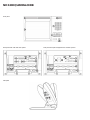 2
2
-
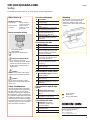 3
3
-
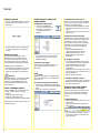 4
4
-
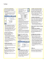 5
5
-
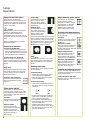 6
6
-
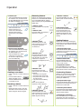 7
7
-
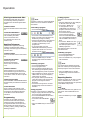 8
8
-
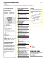 9
9
-
 10
10
-
 11
11
-
 12
12
-
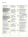 13
13
-
 14
14
-
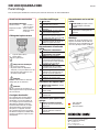 15
15
-
 16
16
-
 17
17
-
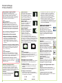 18
18
-
 19
19
-
 20
20
-
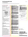 21
21
-
 22
22
-
 23
23
-
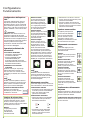 24
24
-
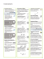 25
25
-
 26
26
-
 27
27
-
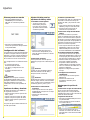 28
28
-
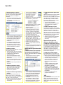 29
29
-
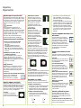 30
30
-
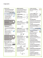 31
31
-
 32
32
-
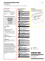 33
33
-
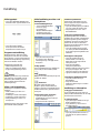 34
34
-
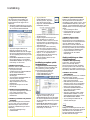 35
35
-
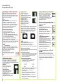 36
36
-
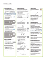 37
37
-
 38
38
-
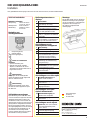 39
39
-
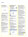 40
40
-
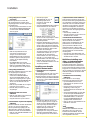 41
41
-
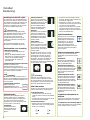 42
42
-
 43
43
-
 44
44
-
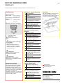 45
45
-
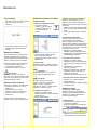 46
46
-
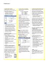 47
47
-
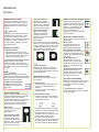 48
48
-
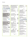 49
49
-
 50
50
-
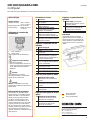 51
51
-
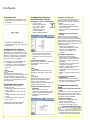 52
52
-
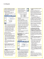 53
53
-
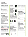 54
54
-
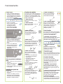 55
55
-
 56
56
-
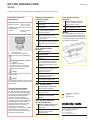 57
57
-
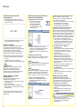 58
58
-
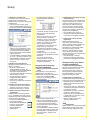 59
59
-
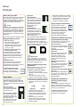 60
60
-
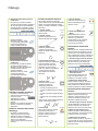 61
61
-
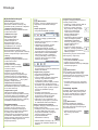 62
62
-
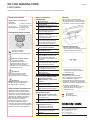 63
63
-
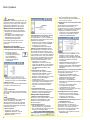 64
64
-
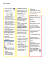 65
65
-
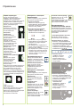 66
66
-
 67
67
-
 68
68
-
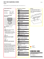 69
69
-
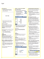 70
70
-
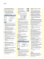 71
71
-
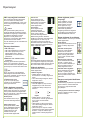 72
72
-
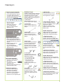 73
73
-
 74
74
-
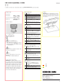 75
75
-
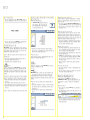 76
76
-
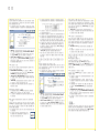 77
77
-
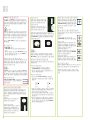 78
78
-
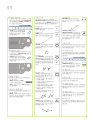 79
79
-
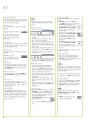 80
80
-
 81
81
-
 82
82
-
 83
83
-
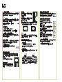 84
84
-
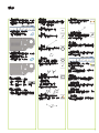 85
85
-
 86
86
-
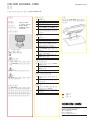 87
87
-
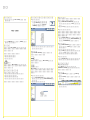 88
88
-
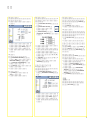 89
89
-
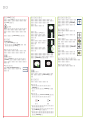 90
90
-
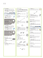 91
91
-
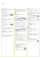 92
92
-
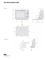 93
93
-
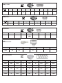 94
94
-
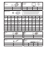 95
95
-
 96
96


HEIDENHAIN ND 1300 - V2.1.0 GUIDE El kitabı
- Tip
- El kitabı
- Bu kılavuz aynı zamanda aşağıdakiler için de uygundur:
diğer dillerde
- español: HEIDENHAIN ND 1300 - V2.1.0 GUIDE El manual del propietario
- français: HEIDENHAIN ND 1300 - V2.1.0 GUIDE Le manuel du propriétaire
- italiano: HEIDENHAIN ND 1300 - V2.1.0 GUIDE Manuale del proprietario
- svenska: HEIDENHAIN ND 1300 - V2.1.0 GUIDE Bruksanvisning
- 日本語: HEIDENHAIN ND 1300 - V2.1.0 GUIDE 取扱説明書
- čeština: HEIDENHAIN ND 1300 - V2.1.0 GUIDE Návod k obsluze
- polski: HEIDENHAIN ND 1300 - V2.1.0 GUIDE Instrukcja obsługi
- Deutsch: HEIDENHAIN ND 1300 - V2.1.0 GUIDE Bedienungsanleitung
- português: HEIDENHAIN ND 1300 - V2.1.0 GUIDE Manual do proprietário
- English: HEIDENHAIN ND 1300 - V2.1.0 GUIDE Owner's manual
- русский: HEIDENHAIN ND 1300 - V2.1.0 GUIDE Инструкция по применению
- Nederlands: HEIDENHAIN ND 1300 - V2.1.0 GUIDE de handleiding
İlgili makaleler
Diğer belgeler
-
Logitech Circle 2 Hızlı başlangıç Kılavuzu
-
ACU-RITE INSTALLATION GUIDE Kullanım kılavuzu
-
Yamaha V2 El kitabı
-
Yamaha V3 El kitabı
-
-
-
-
-
-
SICK Sicherheits-Encoder Kullanma talimatları