
Mainboard
Short Description
Deutsch, English, Русский,
Français, Türkçe, Ελληνικά
Mainboard D2151

Sie haben technische Fragen oder Probleme?
Wenden Sie sich bitte an:
● Ihren zuständigen Vertriebspartner oder Ihre Verkaufsstelle
● unsere Hotline über das Kontaktformular unter www.fujitsu-siemens.com/support/contact/
contact.html oder für Kunden, die ein einzelnes Mainboard gekauft haben: +49(0) 180 3777 005
Aktuelle Informationen und Updates (z. B. BIOS-Update) zu unseren Mainboards finden Sie im
Internet: http://www.fujitsu-siemens.com/mainboards
Are there any technical problems or other questions you need clarified?
Please contact:
● your sales partner or your sales outlet
● unsere Hotline über das Kontaktformular unter www.fujitsu-siemens.com/support/contact/
contact.html oder für Kunden, die ein einzelnes Mainboard gekauft haben: +49(0) 180 3777 005
The latest information and updates (e.g. BIOS update) on our mainboards can be found on the
Internet under: http://www.fujitsu-siemens.com/mainboards
Vous avez des questions ou des problèmes techniques ?
Adressez-vous :
● à votre partenaire de vente ou à votre point de vente
● à notre hotline au moyen du formulaire de contact que vous trouverez à l'adresse www.fujitsu-
siemens.com/support/contact/contact.html ou par téléphone pour les clients qui ont acheté une
carte mère séparée au : +49(0) 180 3777 005
Vous trouverez des informations actualisées et des mises à jour sur notre site (p. ex. BIOS-Update)
sur nos cartes mères sur notre site: http://www.fujitsu-siemens.com/mainboards
У Вас есть технические вопросы или проблемы?
Просим Вас обратиться:
● к Вашему дилеру или в магазин, в котором Вы приобрели устройство
● к сотрудникам нашей горячей линии, указанной в контактном формуляре на сайте:
www.fujitsu-siemens.com/support/contact/ contact.html или же, для заказчиков, которые купили
отдельную материнскую плату, по телефону: +49(0) 180 3777 005
Актуальную информацию и обновленные редакции программ (например, BIOS-Update) для наших
материнских плат Вы найдете в Интернете на сайте: http://www.fujitsu-siemens.com/mainboards
Sizin teknik sorularınız veya sorunlarınız mı var?
Lütfen:
● Sizin için sorumlu dağıtım partneri veya satın aldığınız yer
● www.fujitsu-siemens.com/support/contact/ contact.html adresindeki irtibat formu üzerinden
Hotline'ımıza başvurun veya yalnızca tek bir anakart satın alan müşterilerimiz için:
+49(0) 180 3777 005
Anakartlarımız (Mainboards) ile ilgili oalrak aktüel bilgileri ve güncelleştirmeleri (örneğin BIOS-
Update) internette bulabilirsiniz: http://www.fujitsu-siemens.com/mainboards
Έχετε τεχνικές απορίες ή προβλήµατα?
Παρακαλούµε απευθυνθείτε:
● Στον υπεύθυνο συνεργάτη ή κατάστηµα πώλησης
● Στο τµήµα Hotline µέσω της φόρµας επικοινωνίας στη διεύθυνση www.fujitsu-
siemens.com/support/contact/ contact.html ή για πελάτες που αγοράσανε µόνο µία µητρική κάρτα
στο τηλέφωνο: +49(0) 180 3777 005
Τρέχουσες πληροφορίες και ενηµερώσεις (π.χ. ενηµέρωση BIOS) για τις µητρικές µας κάρτες θα
βρείτε στο Internet: http://www.fujitsu-siemens.com/mainboards

Copyright © Fujitsu Siemens Computers GmbH 2005
Intel, Pentium and Celeron are registered trademarks of Intel Corporation, USA.
Microsoft, MS, MS-DOS and Windows are registered trademarks of Microsoft Corporation.
PS/2 and OS/2 Warp are registered trademarks of International Business Machines, Inc.
All other trademarks referenced are trademarks or registered trademarks of their respective
owners, whose protected rights are acknowledged.
All rights, including rights of translation, reproduction by printing, copying or similar methods,
even of parts are reserved.
Offenders will be liable for damages.
All rights, including rights created by patent grant or registration of a utility model or design,
are reserved. Delivery subject to availability.
Right of technical modification reserved.

Dieses Handbuch wurde erstellt von
cognitas. Gesellschaft für Technik-Dokumentation mbH – www.cognitas.de
Dieses Handbuch wurde auf Recycling-Papier gedruckt.
This manual has been printed on recycled paper.
Ce manuel est imprimé sur du papier recyclé.
Este manual ha sido impreso sobre papel reciclado.
Questo manuale è stato stampato su carta da riciclaggio.
Denna handbok är tryckt på recyclingpapper.
Dit handboek werd op recycling-papier gedrukt.
Herausgegeben von/Published by
Fujitsu Siemens Computers GmbH
Printed in the Federal Republic of Germany
AG 06/05
Ausgabe/Edition 2
Bestell-Nr./Order No.: A26361-D2151-Z110-1-8N19
A26361-D2151-Z110-1-8N19

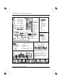
Mainboard D2151 - Internal connectors and slots
A26361-D2151-Z110-1-8N19, edition 2
USB - dual channel
2
1
10
9
1 = VCC x
2 = VCC y
3 = Data negative x
4 = Data negative y
5 = Data positive x
6 = Data positive y
7 = GND
8 = GND
9 = Key
10 = Not connected
PCI 1
PCI 2
Floppy disk drive
Front panel
IDE-drives 1/2
Serial ATA4
Serial ATA3
Fan 2
Battery
USB
Power supply
Serial ATA2
Serial ATA1
slot 1
slot 3
slot 4
slot 2
Channel B
Channel A
Additional power
supply +12 V
Fan 1
COM2 / Serial 2
PCI Express x1
PCI Express x16
Intrusion
TPM jumper
Fan 3
Audio front panel
Audio in
Fan 4
Power supply control
Optionale Komponenten / Optional components
Audio In (optional)
1
1 = Left audio input
2 = Analog GND
3 = Analog GND
4 = Right audio input
High Definition Audio (default)
1
2
1 = Micro input Left
2 = Analog GND
3 = Micro input
Right
4 = Presence
Detect
5 = Right line / Headphone
output
6 = Sense 1 return
7 = Jack sense Send
8 = Key
9 = Left line / Headphone output
10 = Sense 2 return
Front panel
1) Both jumper positions possible
2) 2pin or 3pin connector possible
1
2
HD-LED
Power On/Off
Recovery Password
1)
Reset
Power On
LED
2)
Message LED
Speaker
External connectors
Recovery inserted = The system starts from
floppy and allows a BIOS recovery
Password inserted = System- and BIOS
Password are skipped when device is
switched on
A26361-D2151-Z140-1-7619

Mainboard D2151
A26361-D2151-Z110-1-8N19, edition 2
List of onboard features D2151-A
Chipset Intel
®
945G
Board size µATX
VGA
Audio / 6-channel / S/PDIF / - / -
Buzzer / int. Speaker Support - /
LAN 1 Gbit / 100 Mbit / 10 Mbit / /
LAN ASF / AoL / WoL / Boot / - / /
Serial ATA2 / ATA / RAID / / -
FireWire
TM
/ USB 2.0 - /
FAN monitored PSU** / CPU (FAN1) / AUX1 (FAN2) / AUX2 (FAN3) / / / -
FAN controlled PSU** / CPU (FAN1) / AUX1 (FAN2) / AUX2 (FAN3) / / / -
TEMP monitored CPU/ONB1/ONB2/HDD / / /
SmartCard SystemLock (USB / serial) / -
Fujitsu Siemens Computers Keyboard Power Button Support
List of special onboard features
Silent Fan / Silent Fan LT / -
System Guard / Silent Drives /
Recovery BIOS / Desk Update / Multi Boot / Safe Standby / / /
HDD Password / USB Security / -
Logo Boot / Intel On Screen Branding /
** not supported by standard Power Supplies
Special Features
Green Edition Halogen-free and lead-reduced product
Silent Fan Independent temperature related processor and fan supervision and control
System Guard View and adjust Silent Fan
Silent Drives Noise reduction for optical and hard disk drives
Safe Standby Prevents data loss in S3 (Save-to-RAM)
Recovery BIOS Restores a disrupted BIOS
Desk Update Simple driver update with DU CD
Multi Boot Comfortable boot from any boot device
HDD Password Access protection for ATA5/ATAPI5 hard disk drives
Power Supply Requirements
- for onboard components (worst case)
Source Voltage Maximal variation Mainboard current (Maximal)
+ 12 V 5 % 10.0 A
Main Power - 12 V 10 % 0.05 A
Supply + 5 V 5 % 6 A
+ 3.3 V 5 % 4 A
Aux. Power Supply + 5 V 5 % 2 A

A26361-D2151-Z110-1-8N19, Ausgabe 2 Deutsch - 1
Mainboard D2151
Hinweise zu Baugruppen
Beachten Sie bei Baugruppen mit EGB unbedingt Folgendes:
● Sie müssen sich statisch entladen (z. B. durch Berühren eines geerdeten
Gegenstandes), bevor Sie mit Baugruppen arbeiten.
● Verwendete Geräte und Werkzeuge müssen frei von statischer Aufladung sein.
● Ziehen Sie den Netzstecker, bevor Sie Baugruppen stecken oder ziehen.
● Fassen Sie die Baugruppen nur am Rand an.
● Berühren Sie keine Anschluss-Stifte oder Leiterbahnen auf der Baugruppe.
Eine Übersicht der Leistungsmerkmale finden Sie im Datenblatt!
Besondere Merkmale
Ihr Mainboard ist in verschiedenen Ausbaustufen erhältlich. Abhängig von der Konfiguration Ihres
Mainboards besitzt oder unterstützt das Mainboard bestimmte Merkmale.
In diesem Handbuch finden Sie die wichtigsten Eigenschaften dieses Mainboards beschrieben.
Weitere Informationen zu Mainboards finden Sie im Handbuch "Basisinformationen Mainboard" auf
der CD "User Documentation" oder "OEM Mainboard" bzw. im Internet.
Anschlüsse und Steckverbinder
Die Position der Anschlüsse und Steckverbinder Ihres Mainboards finden Sie am Anfang des
Handbuches.
Die markierten Komponenten und Steckverbinder müssen nicht auf dem Mainboard vorhanden sein.
Externe Anschlüsse
Die Position der externen Anschlüsse Ihres Mainboards finden Sie am Anfang des Handbuches.
PS/2-Tastaturanschluss, violett
Serielle Schnittstelle, türkis
Parallele Schnittstelle/Drucker,
burgund
PS/2-Mausanschluss, grün
LAN
LAN-Anschluss (RJ-45)
Mikrofonanschluss, rosa
Audioeingang (Line in), hellblau
USB - Universal Serial Bus, schwarz
Audioausgang (Line out), hellgrün

Mainboard D2151
2 - Deutsch A26361-D2151-Z110-1-8N19, Ausgabe 2
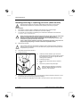
Prozessor ein- / ausbauen oder tauschen (mit Kühlkörper)
!
Für alle hier beschriebenen Arbeiten muss Ihr System vollständig von der Netzspannung
getrennt sein! Nähere Angaben dazu finden Sie in der Betriebsanleitung Ihres Systems.
Technische Daten
● Intel Pentium 4 mit 533, 800 oder 1066 MHz Front Side Bus in der Bauform LGA775
● Intel Celeron D, mit 533 MHz Front Side Bus in der Bauform LGA775
● Eine aktuelle Liste der von diesem Mainboard unterstützten Prozessoren finden Sie im Internet
unter: www.fujitsu-siemens.com/mainboards.
!
Fassen Sie auf keinen Fall die Unterseite des Prozessors an. Schon leichte
Verunreinigungen wie Fett von der Haut können die Funktion des Prozessors
beeinträchtigen oder den Prozessor zerstören.
Setzen Sie den Prozessor mit großer Sorgfalt in den Steckplatz, da die
Federkontakte des Steckplatzes sehr empfindlich sind und nicht verbogen werden
dürfen.
Sind ein oder mehrere Federkontakte verbogen, setzen Sie auf keinen Fall den
Prozessor ein, da dieser dadurch beschädigt werden könnte. Wenden Sie sich bitte
direkt an Ihren zuständigen Händler.
► Entfernen Sie den Kühlkörper.
!
Der Steckplatz für den Prozessor ist zum Schutz der Federkontakte mit einer Schutzkappe
abgedeckt. Im Garantiefall kann das Mainboard nur mit befestigter Schutzkappe von
Fujitsu Siemens Computers zurückgenommen werden!
► Drücken Sie auf den Hebel und haken Sie ihn aus.
► Klappen Sie die Halterung nach oben.
a
b
b
► Halten Sie den Prozessor mit Daumen und
Zeigefinger und stecken Sie ihn so in den
Steckplatz (b), dass die Markierung des
Prozessors mit der Markierung am Steckplatz von
der Lage her übereinstimmt (a).
► Klappen Sie die Halterung nach unten.
► Drücken Sie den Hebel nach unten, bis er wieder
einhakt.
► Entfernen Sie die Schutzkappe und verwahren
Sie diese.
!
Bitte beachten Sie, dass je nach
verwendetem Kühlkörper unterschiedliche
Kühlkörperhalterungen auf dem Mainboard
benötigt werden.
► Je nach Ausbau-Variante müssen Sie eine Schutzfolie vom Kühlkörper abziehen oder den
Kühlkörper mit Wärmeleitpaste bestreichen, bevor Sie ihn aufsetzen.
► Befestigen Sie den Kühlkörper - je nach Ausführung - mit vier Schrauben oder stecken Sie ihn
in die Befestigungen.

Mainboard D2151
A26361-D2151-Z110-1-8N19, Ausgabe 2 Deutsch - 3
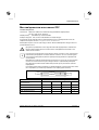
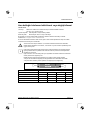
Hauptspeicher ein-/ausbauen oder tauschen
Technische Daten
Technologie: DDR2 400 / DDR2 533 / DDR2 667 ungepufferte DIMM-Module
240-Pin; 1,8 V; 64 Bit, ohne ECC
Gesamtgröße: 256 Mbytes bis 4 Gbyte DDR2
Modulgrößen: 256, 512 oder 1024 Mbyte pro Modul
Eine aktuelle Liste der für dieses Mainboard empfohlenen Speichermodule finden Sie im Internet
unter: www.fujitsu-siemens.com/mainboards.
Es muss mindestens ein Speichermodul eingebaut sein. Speichermodule mit unterschiedlicher
Speicherkapazität können kombiniert werden.
!
Es dürfen nur ungepufferte 1,8 V-Speichermodule ohne ECC verwendet werden.
DDR2-Speichermodule müssen der PC2-3200U-, PC2-4200U- oder PC2-5300U-
Spezifikation entsprechen.
i
Wenn Sie mehr als ein Speichermodul verwenden, dann achten Sie darauf, die
Speichermodule auf beide Speicherkanäle aufzuteilen. Dadurch nutzen Sie die
Performancevorteile des Dual-Channel-Mode.
Die maximale Systemperformance ist gegeben, wenn in Channel A und Channel B die
gleiche Speichergröße verwendet wird.
Um die Bestückung zu erleichtern, sind die Steckplätze (Slots) farbig gekennzeichnet.
Bei einer Speicherkonfiguration von 4 Gbyte kann der sichtbare und benutzbare
Hauptspeicher auf bis zu 3 Gbyte reduziert sein (abhängig von der Konfiguration des
Systems).
Channel A
Channel B
slot 2
slot 1
slot 4
slot 3
Anzahl der gesteckten Speichermodule
zu verwendender Steckplatz 1 2 3 4
Channel A, Slot 1 X X X X
Channel A, Slot 3 X X
Channel B, Slot 2 X X X
Channel B, Slot 4 X
Der Ein-/Ausbau ist im Handbuch "Basisinformationen Mainboard" beschrieben.

Mainboard D2151
4 - Deutsch A26361-D2151-Z110-1-8N19, Ausgabe 2
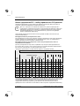
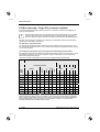
PCI-Bus-Interrupts - Auswahl des richtigen PCI-Steckplatzes
Umfangreiche Informationen zu diesem Abschnitt finden Sie im Handbuch "Basisinformationen
Mainboard".
i
Um optimale Stabilität, Performance und Kompatibilität zu erreichen, vermeiden Sie die
mehrfache Nutzung von ISA IRQs oder PCI IRQ Lines (IRQ Sharing). Sollte IRQ Sharing
nicht zu umgehen sein, so müssen alle beteiligten Geräte und deren Treiber IRQ Sharing
unterstützen.
Welche ISA IRQs den PCI IRQ Lines zugeordnet werden, wird normalerweise automatisch vom
BIOS festgelegt (siehe Beschreibung "BIOS-Setup").
Monofunktionale Erweiterungskarten
PCI-/PCI-Express-Erweiterungskarten benötigen maximal einen Interrupt, der als PCI-Interrupt INT A
bezeichnet wird. Erweiterungskarten, die keinen Interrupt benötigen, können in einen beliebigen
Steckplatz eingebaut werden.
Multifunktionale Erweiterungskarten oder Erweiterungskarten mit integrierter PCI-PCI Bridge
Diese Erweiterungskarten benötigen bis zu vier PCI-Interrupts: INT A, INT B, INT C, INT D. Wie viele
und welche dieser Interrupts verwendet werden, entnehmen Sie der mitgelieferten Dokumentation
der Karte.
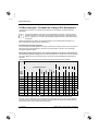
Die Zuordnung der PCI-Interrupts zu den IRQ Lines finden Sie in der folgenden Tabelle:
Controller or slot INT
Mechanical slot
On board controller
1 2 3 4 - -
USB 1.1 PCIe PCI
PCI
INT
LINE
1
st
2
nd
3
rd
4
th
USB 2.0
SMBus
HD Audio
LAN
x16 x1 - 1 2 - -
1 (A) -
-
-
- - - X X A D
-
- -
- -
2 (B) -
-
-
- - - - - B A
-
- -
-
3 (C)
-
-
-
- - - - - - B
-
D C
- -
4 (D)
-
-
-
- - X - - - C
-
C D
- -
5 (E)
-
-
-
X - - - - - -
-
- -
- -
6 (F)
-
-
X
- - - - - - -
-
B A
- -
7 (G)
-
X
-
- - - - - - -
-
A B
- -
8 (H)
X
-
-
- X - - - - -
-
- -
- -
Verwenden Sie zuerst PCI-/PCI-Express-Steckplätze, die über eine einzige PCI IRQ Line verfügen
(kein IRQ Sharing). Wenn Sie einen anderen PCI-/PCI-Express-Steckplatz mit IRQ Sharing
benutzen müssen, überprüfen Sie, ob die Erweiterungskarte IRQ Sharing mit den anderen Geräten
auf dieser PCI IRQ Line einwandfrei unterstützt. Auch die Treiber aller Karten und Komponenten an
dieser PCI IRQ Line müssen IRQ Sharing unterstützen.

Mainboard D2151
A26361-D2151-Z110-1-8N19, Ausgabe 2 Deutsch - 5
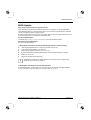
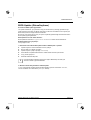
BIOS-Update
Wann sollte ein BIOS-Update durchgeführt werden?
Fujitsu Siemens Computers stellt neue BIOS-Versionen zur Verfügung, um die Kompatibilität zu
neuen Betriebssystemen, zu neuer Software oder zu neuer Hardware zu gewährleisten. Außerdem
können neue BIOS-Funktionen integriert werden.
Ein BIOS-Update sollte auch immer dann durchgeführt werden, wenn ein Problem besteht, das sich
durch neue Treiber oder neue Software nicht beheben lässt.
Wo gibt es BIOS-Updates?
Im Internet unter www.fujitsu-siemens.com/mainboards finden Sie die BIOS-Updates.
Wie funktioniert ein BIOS-Update?
Sie haben zwei Möglichkeiten:
1. BIOS-Update unter DOS mit startfähiger BIOS-Update-Diskette - Kurzbeschreibung
► Laden Sie die Update-Datei von unserer Internet-Seite auf Ihren PC.
► Legen Sie eine leere Diskette (1,44 Mbyte) ein.
► Führen Sie die Update-Datei aus (z. B. 2151103.EXE).
► Es wird eine startfähige Update-Diskette erstellt. Lassen Sie diese Diskette im Laufwerk.
► Starten Sie den PC neu.
► Folgen Sie den Bildschirmanweisungen.
i
Detaillierte Informationen zum BIOS-Update unter DOS finden Sie im Handbuch zum
"BIOS-Setup" (CD "Drivers & Utilities").
2. BIOS-Update unter Windows mit dem Utility DeskFlash
Ein BIOS-Update kann mit dem Utility DeskFlash auch direkt unter Windows durchgeführt werden.
DeskFlash befindet sich auf der CD "Drivers & Utilities" (unter DeskUpdate).

Mainboard D2151
6 - Deutsch A26361-D2151-Z110-1-8N19, Ausgabe 2
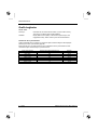
Grafik-Anschluss
Technische Daten
Funktion: Intel GMA 950, 2D-/3D-Grafik-Controller, Dynamic Video memory
Technology, 400 Mhz integrierter 24-Bit-RAMDAC
Merkmale: Display Data Channel (DDC), 2 SDVO-Kanäle (bis zu 165 Megapixel pro
Kanal), Dual-View-Unterstützung für ADD2+-Karten
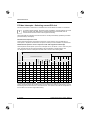
Unterstützte Bildschirmauflösungen
Abhängig vom verwendeten Betriebssystem gelten die nachfolgend angegebenen
Bildschirmauflösungen für den Bildschirm-Controller auf dem Mainboard.
Wenn Sie einen anderen Bildschirm-Controller verwenden, finden Sie die unterstützten
Bildschirmauflösungen in der Dokumentation zum Bildschirm-Controller.
Bildschirmauflösung Bildwiederholfrequenz [Hz] Farben
640 x 480 120 32 bit
800 x 600 120 32 bit
1024 x 768 100 32 bit
1280 x 1024 100 32 bit
1600 x 1200 100 16 bit
1920 x 1440 75 16 bit
2048 x 1536 75 16 bit

A26361-D2151-Z110-1-8N19, edition 2 English - 1
Mainboard D2151
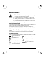
Information about boards
Be sure to observe the following for boards with ESD:
● You must always discharge static build up (e.g. by touching a grounded object)
before working.
● The equipment and tools you use must be free of static charges.
● Remove the power plug from the mains supply before inserting or removing
boards containing ESDs.
● Always hold boards with ESDs by their edges.
● Never touch pins or conductors on boards fitted with ESDs.
An overview of the features is provided in the data sheet.
Special features
Your mainboard is available in different configuration levels. Depending on the configuration, your
mainboard is equipped with or supports special features.
This manual describes the most important properties of this mainboard.
Additional information on mainboards is contained in the manual "Basic information on mainboard"
on the "User Documentation" or "OEM Mainboard" CDs, or on the Internet.
Interfaces and connectors
The location of the interfaces and connectors of your mainboard is specified at the beginning of the
manual.
The components and connectors marked are not necessarily present on the mainboard.
External ports
The location of the external connections of your mainboard is specified at the beginning of the
manual.
PS/2 keyboard port, purple
Serial interface, turquoise
Parallel port/Printer, burgundy
PS/2 mouse port, green
LAN
LAN port (RJ-45)
Microphone jack (mono), pink
Audio input (Line in), light blue
USB - Universal Serial Bus, black
Audio output (Line out), light green

Mainboard D2151
2 - English A26361-D2151-Z110-1-8N19, edition 2
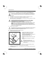
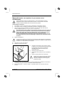
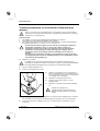
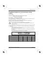
Installing/removing or replacing processor (with heat sink)
!
Disconnect the system from the mains voltage before performing any of the tasks
described below. Details are contained in the operating manual of your system.
Technical data
● Intel Pentium 4 with 533, 800 or 1066 MHz front side bus in the LGA775 design
● Intel Celeron D with 533 MHz Front Side Bus in the LGA775 design
● A current list of the processors supported by this mainboard is available on the Internet at:
www.fujitsu-siemens.com/mainboards.
!
Never touch the underside of the processor. Even minor soiling such as grease from
the skin can impair the processor's operation or destroy the processor.
Place the processor in the socket with extreme care, as the spring contacts of the
socket are very delicate and must not be bent.
If one or more spring contacts are bent do not insert the processor in any case as it
may be damaged by doing so. Please contact the responsible vendor.
► Remove the heat sink.
!
The processor socket ist covered with a protective cap to protect the spring contacts In a
warranty case the mainboard can only be taken back by Fujitsu Siemens Computers with
the protective cap secured!
► Press down the lever and unhook it.
► Fold up the frame.
a
b
b
► Hold the processor between your thumb and
index finger and insert it into the socket (b) so that
the marking of the processor is aligned with the
marking on the socket (a).
► Fold down the frame.
► Press the lever downward until it is hooked in
again.
► Remove the protective cap and keep it.
!
Please note that, depending on the heat
sink used, different heat sink mounts are
required on the mainboard.
► Depending on the configuration variant, you must pull a protective foil off the heat sink or coat
the heat sink with heat conducting paste before fitting it.
► Secure the heat sink - depending on the model - with four screws or push it into the mounts.

Mainboard D2151
A26361-D2151-Z110-1-8N19, edition 2 English - 3
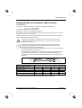
Installing/removing or replacing main memory
Technical data
Technology: DDR2 400 / DDR2 533 / DDR2 667 unbuffered DIMM modules
240-Pin; 1.8 V; 64 Bit, no ECC
Size: 256 MB to 4 GB DDR2
Granularity: 256, 512 or 1024 Mbyte for one socket
A current list of the memory modules recommended for this mainboard is available on the Internet
at: www.fujitsu-siemens.com/mainboards.
At least one memory module must be installed. Memory modules with different memory capacities
can be combined.
!
You may use only unbuffered 1.8 V memory modules without ECC.
DDR2-memory modules must meet the PC2-3200U, PC2-4200U or PC2-5300U
specification.
i
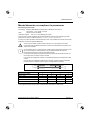
If you use more than one memory module, then make sure to distribute the memory
modules over both memory channels. By doing this you use the performance advantages
of the dual-channel mode.
The maximum system performance is given when the same memory size is used in
Channel A and Channel B.
To simplify equipping, the slots are colour coded.
With a memory configuration of 4 Gbytes the visible and usable main memory can be
reduced down to 3 Gbytes (depending on the system configuration).
Channel A
Channel B
slot 2
slot 1
slot 4
slot 3
Number of inserted memory modules
slot to be used 1 2 3 4
Channel A, slot 1 X X X X
Channel A, slot 3 X X
Channel B, slot 2 X X X
Channel B, slot 4 X
The installation/removal is described in the "Basic information on mainboard" manual.

Mainboard D2151
4 - English A26361-D2151-Z110-1-8N19, edition 2
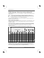
PCI bus interrupts - Selecting correct PCI slot
Extensive information on this section is contained in the manual "Basic information on mainboard".
i
To achieve optimum stability, performance and compatibility, avoid the multiple use of ISA
IRQs or PCI IRQ Lines (IRQ sharing). Should IRQ sharing be unavoidable, then all
involved devices and their drivers must support IRQ sharing.
Which ISA IRQs are assigned to the PCI IRQ Lines is normally automatically specified by the BIOS
(see "BIOS Setup" description).
Monofunctional expansions cards
PCI/PCI Express expansion cards require a maximum of one interrupt, which is called the PCI
interrupt INT A. Expansion cards that do not require an interrupt can be installed in any desired slot.
Multifunctional expansion cards or expansion cards with integrated PCI-PCI bridge
These expansion cards require up to four PCI interrupts: INT A, INT B, INT C, INT D. How many and
which of these interrupts are used is specified in the documentation provided with the card.
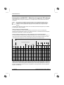
The assignment of the PCI interrupts to the IRQ Lines is shown in the following table:
Controller or slot INT
Mechanical slot
On board controller
1 2 3 4 - -
USB 1.1 PCIe PCI
PCI
INT
LINE
1
st
2
nd
3
rd
4
th
USB 2.0
SMBus
HD Audio
LAN
x16 x1 - 1 2 - -
1 (A) -
-
-
- - - X X A D
-
- -
- -
2 (B) -
-
-
- - - - - B A
-
- -
-
3 (C)
-
-
-
- - - - - - B
-
D C
- -
4 (D)
-
-
-
- - X - - - C
-
C D
- -
5 (E)
-
-
-
X - - - - - -
-
- -
- -
6 (F)
-
-
X
- - - - - - -
-
B A
- -
7 (G)
-
X
-
- - - - - - -
-
A B
- -
8 (H)
X
-
-
- X - - - - -
-
- -
- -
Use first PCI/PCI Express slots that have a single PCI IRQ Line (no IRQ sharing). If you must use
another PCI/PCI Express slot with IRQ sharing, check whether the expansion card properly supports
IRQ sharing with the other devices on this PCI IRQ Line. The drivers of all cards and components on
this PCI IRQ Line must also support IRQ sharing.

Mainboard D2151
A26361-D2151-Z110-1-8N19, edition 2 English - 5
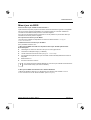
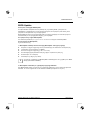
BIOS update
When should a BIOS update be carried out?
Fujitsu Siemens Computers makes new BIOS versions available to ensure compatibility to new
operating systems, new software or new hardware. In addition, new BIOS functions can also be
integrated.
A BIOS update should always also be carried out when a problem exists that cannot be solved with
new drivers or new software.
Where can I obtain BIOS updates?
The BIOS updates are available on the Internet at www.fujitsu-siemens.com/mainboards.
How does a BIOS update work?
You have two ways of doing this:
1. BIOS update under DOS with bootable BIOS update floppy disk - brief description
► Download the update file from out website to your PC.
► Insert an empty floppy disk (1.44 Mbyte).
► Run the update file (e.g. 2151103.EXE).
► A bootable update floppy disk is created. Leave this floppy disk in the drive.
► Restart the PC.
► Follow the instructions on screen.
i
Detailed information on the BIOS update under DOS is provided in the manual on "BIOS
Setup" ("Drivers & Utilities" CD).
2. BIOS update under Windows with DeskFlash utility
A BIOS update can also be carried out directly under Windows with the DeskFlash utility. DeskFlash is
contained on the "Drivers & Utilities" CD (under DeskUpdate).

Mainboard D2151
6 - English A26361-D2151-Z110-1-8N19, edition 2
Graphics port
Technical data
Function: Intel GMA 950, 2D/3D graphics controller, Dynamic Video memory
Technology, 400 Mhz integrated 24-bit RAMDAC
Features: Display Data Channel (DDC), 2 SDVO channels (up to 165 megapixels per
channel), dual-view support for ADD2+ boards
Screen resolution
Depending on the operating system used, the screen resolutions in the following table refer to the
mainboard screen controller.
If you are using an external screen controller, you will find details of supported screen resolutions in
the operating manual or technical manual supplied with the controller.
Display resolution Refresh rate (Hz) Colour
640 x 480 120 32 bit
800 x 600 120 32 bit
1024 x 768 100 32 bit
1280 x 1024 100 32 bit
1600 x 1200 100 16 bit
1920 x 1440 75 16 bit
2048 x 1536 75 16 bit

A26361-D2151-Z110-1-8N19, издание 2 Русский - 1
Mainboard D2151
Указания по модулям
Для модулей с EGB обязательно учитывайте следующее:
● Перед работой с модулями требуется статически разрядить свое тело
(например посредством касания какого-либо заземленного предмета).
● Исключить возможность статического заряда используемых устройств и
инструментов.
● Перед установкой или снятием модулей выньте вилку сетевого кабеля из
розетки.
● Касайтесь только кромок модулей.
● Не прикасайтесь к штифтовым выводам или печатным проводникам модуля.
Обзор производственных показателей Вы найдете в техническом паспорте!
Отличительные особенности
Вы можете приобрести Вашу материнскую плату в различных конфигурационных исполнениях.
Ваша материнская плата обладает определенными показателями или поддерживает их в
зависимости от её конфигурации.
В этом Руководстве по эксплуатации Вы найдете описание важнейших свойств этой
материнской платы.
Дальнейшую информацию о материнских платах Вы найдете в руководстве "Basic information
on mainboard" («Базисная информация о материнской плате») на компакт-диске "User
Documentation" или "OEM Mainboard" или же в Интернете.
Средства сопряжения и штекерные разъемы
Информацию о расположении средств сопряжения и штекерных разъемов на Вашей
материнской плате Вы найдете в начале Руководства по эксплуатации.
Помеченные компоненты и штекерные разъемы могут отсутствовать на материнской плате.
Внешние средства сопряжения
Информацию о расположении внешних средств сопряжения на Вашей материнской плате Вы
найдете в начале Руководства по эксплуатации.
Порт клавиатуры PS/2,
фиолетовый
последовательный интерфейс,
бирюзовый
Параллельный
интерфейс/принтер, темно-
красный
Порт мыши PS/2, зеленый
LAN
Порт LAN (RJ-45)
Порт микрофона, розовый
Aудиовход (Line in), светло-синий
USB - Universal Serial Bus
(универсальная последовательная
шина), черный
Аудиовыход (Line out), светло-
зеленый

Mainboard D2151
2 - Русский A26361-D2151-Z110-1-8N19, издание 2
Монтаж/демонтаж или замена процессоров (с радиатором)
!
Для осуществления всех описанных здесь работ Ваша система должна быть
полностью отключена от сетевого напряжения! Более подробную информацию об
этом Вы найдете в руководстве по эксплуатации Вашей системы.
Teхнические данные
● Intel Pentium 4 с 533, 800 или 1066 MГц Front Side Bus в конструктивном исполнении
LGA775
● Intel Celeron D с 533 MГц Front Side Bus в конструктивном исполнении LGA775
● Актуальный список процессоров, поддерживаемых этой материнской платой, Вы найдете
в Интернете на сайте: www.fujitsu-siemens.com/mainboards.
!
Ни в коем случае не прикасайтесь к нижней стороне процессора. Уже малейшие
загрязнения, как например, жир на коже, могут негативно сказаться на работе
процессора или же разрушить его.
Устанавливайте процессор в разъем очень осторожно, поскольку пружинные
контакты на разъеме очень чувствительны и их нельзя изгибать.
В том случае, если один или несколько пружинных контактов изогнуты, ни в
коем случае не устанавливайте процессор, поскольку из-за этого он может
быть поврежден. Пожалуйста, обратитесь непосредственно к компетентному
продавцу.
► Удалите радиатор.
!
Разъем для процессора закрыт защитной пластинкой для защиты пружинных
контактов. В случае предъявления гарантийных претензий возвращаемая
материнская плата может быть принята только при наличии прикрепленной
защитной пластинки фирмы Fujitsu Siemens Computers!
► Нажмите на рычаг и поднимите его.
► Поднимите устройство крепления вверх.
a
b
b
► Держите процессор большим и указательным
пальцами и вставьте его в разъем (b) так,
чтобы маркировка на процессоре по своему
расположению полностью совпала с
маркировкой на разъеме (а).
► Опустите устройство крепления вниз.
► Нажмите на рычаг вниз до щелчка,
означающего, что процессор закреплен.
► Удалите защитную пластинку и сохраняйте ее.
!
Пожалуйста, учитывайте то, что в
зависимости от используемого радиатора
на материнской плате требуются
различные устройства крепления
радиатора.
► В зависимости от варианта конфигурации перед установкой радиатора Вы должны снять
защитную пленку с радиатора, или же покрыть радиатор теплопроводящей пастой.
► Укрепите радиатор (в зависимости от конфигурации) при помощи четырех шурупов или
же вставьте его в крепеж.
Sayfa yükleniyor ...
Sayfa yükleniyor ...
Sayfa yükleniyor ...
Sayfa yükleniyor ...
Sayfa yükleniyor ...
Sayfa yükleniyor ...
Sayfa yükleniyor ...
Sayfa yükleniyor ...
Sayfa yükleniyor ...
Sayfa yükleniyor ...
Sayfa yükleniyor ...
Sayfa yükleniyor ...
Sayfa yükleniyor ...
Sayfa yükleniyor ...
Sayfa yükleniyor ...
Sayfa yükleniyor ...
Sayfa yükleniyor ...
Sayfa yükleniyor ...
Sayfa yükleniyor ...
Sayfa yükleniyor ...
Sayfa yükleniyor ...
Sayfa yükleniyor ...
-
 1
1
-
 2
2
-
 3
3
-
 4
4
-
 5
5
-
 6
6
-
 7
7
-
 8
8
-
 9
9
-
 10
10
-
 11
11
-
 12
12
-
 13
13
-
 14
14
-
 15
15
-
 16
16
-
 17
17
-
 18
18
-
 19
19
-
 20
20
-
 21
21
-
 22
22
-
 23
23
-
 24
24
-
 25
25
-
 26
26
-
 27
27
-
 28
28
-
 29
29
-
 30
30
-
 31
31
-
 32
32
-
 33
33
-
 34
34
-
 35
35
-
 36
36
-
 37
37
-
 38
38
-
 39
39
-
 40
40
-
 41
41
-
 42
42


