
351000
07/17-01 PC
O1677C
BTicino SpA – Viale Borri, 231 – 21100 Varese – Italy – www.bticino.com
5
4
1
3
2
2
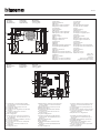
1. Lautsprecher
2. Ruftasten
3. Mikrofon
4. Lautstärkeregulierung Lautsprecher
5. Lautstärkeregulierung Mikrofon
1. Altoparlante
2. Pulsanti di chiamata
3. Microfono
4. Regolazione volume altoparlante
5. Regolazione volume microfono
1. Hoparlör
2. Arama butonları
3. Mikrofon
4. Hoparlör ses ayarı
5. Mikrofon ses ayarı
1. Altavoz
2. Pulsadores de llamada
3. Micrófono
4. Regulación del volumen del altavoz
5. Regulación del volumen del micrófono
1. Altifalante
2. Botões de chamada
3. Microfone
4. Regulação do volume do altifalante
5. Regulação do volume do microfone
1. Haut-parleur
2. Boutons d’appel
3. Micro
4. Réglage volume haut-parleur
5. Réglage volume micro
1. Głośnik
2. Przyciski wywołania
3. Mikrofon
4. Regulacja głośności głośnika
5. Regulacja głośności mikrofonu
1. Loudspeaker
2. Call pushbuttons
3. Microphone
4. Loudspeaker volume adjustment
5. Microphone volume adjustment
1. Ηχείο
2. Πλήκτρα κλήσης
3. Μικρόφωνο
4. Ρύθμιση έντασης ηχείου
5. Ρύθμιση έντασης μικρόφωνου
1. Luidspreker
2. Beltoetsen
3. Microfoon
4. Volume luidspreker afstellen
5. Volume microfoon afstellen
1. Динамик
2. Кнопки вызова
3. Микрофон
4. Регулировка громкости динамика
5. Регулировка громкости микрофона
5
4
3 2 1
6
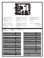
1. Collegamento e comando elettroserratura
(18 V 4 A impulsivi - 250 mA di mantenimento
su 30 Ohm max)
2. Collegamento pulsante apriporta locale
3. Collegamento al BUS
4. Connettore per il collegamento ai moduli tasti
successivi
5. J1 estrarre per attivare due colonne di
pulsanti di chiamata
6. Sede configuratori
1. Anschluss und Steuerung elektr. Türschloss
(18 V 4 A Impuls - 250 mA Haltestrom bei 30
Ohm max.)
2. Anschluss Türöffner lokal
3. BUS - Anschluss
4. Verbinder für Anschluss an weitere Tasten-
module
5. J1 entfernen, um zwei Spalten Ruftasten zu
aktivieren
6. Sitz für Konfiguratoren
1. Electric door lock connection and control (18
V – 4 A impulsive – 250 mA maintenance on 30
Ohm maximum)
2. Local door lock release pushbutton connection
3. Connection to the BUS
4. Connector for the connection to subsequent
key modules
5. J1 remove to activate two columns of call
pushbuttons
6. Configurator socket
1. Conexión y mando electrocerradura (18 V 4A
impulsivos - 250 mA de mantenimiento a 30
ohm máx.)
2. Conexión pulsador de apertura puerta local
3. Conexión al BUS
4. Conector para los módulos de teclas sucesivos
5. J1: sacar para activar las dos columnas de los
pulsadores de llamada
6. Alojamiento de los configuradores
1. Aansluiting en bediening elektrisch slot
(18 V 4 A impulsen - 250 mA behoud op 30
Ohm max)
2. Aansluiting plaatselijke knop openen deur
3. Aansluiting met BUS
4. Connector voor de aansluiting op de vol-
gende modules met toetsen
5. Voor de activering van de twee rijen met bel-
toetsen J1 verwijderen
6. Plaats configuratoren
1. Branchement et commande serrure électrique
(18 V 4 A à impulsions - 250 mA de maintien
sur 30 Ohm max.)
2. Branchement bouton ouverture porte local
3. Branchement au BUS
4. Connecteur de branchement aux modules
touches suivants
5. J1 extraire pour activer deux colonnes de
boutons d’appel
6. Logement configurateurs
• Vista frontale
• Front view
• Vue frontale
• Ansicht von vorn
• Vista frontal
• Vista frontal
• Vooraanzicht
• Εμπρόσθια όψη
• Widok z przodu
• Вид спереди
• Önden görünüş
1
2
3
4
5
• Vista retro
• Back view
• Vue postérieure
• Rückseite
• Vista posterior
• Vista traseira
• Achteraanzicht
• Οπίσθια όψη
• Widok z tyłu
• Вид сзади
• Arkadan görünüş

2
Alimentazione da Bus 18 – 27 Vdc
Assorbimento stand-by 15 mA
Assorbimento massimo in funzionamento 65 mA
Temperatura di funzionamento (- 25) – (+70) °C
Alimentation sur Bus 18 – 27 Vdc
Absorption en stand-by 15 mA
Absorption maximale en fonctionnement 65 mA
Température de fonctionnement (- 25) – (+70) °C
Power supply from BUS 18 – 27 Vdc
Stand-by absorption 15 mA
Max. operating absorption 65 mA
Operating temperature (- 25) – (+70) °C
Speisung über Bus 18 – 27 Vdc
Absorption stand-by 15 mA
Max. Absorption in Betrieb 65 mA
Betriebstemperatur (- 25) – (+70) °C
Alimentación desde BUS 18 – 27 Vdc
Absorción en stand-by 15 mA
Absorción máxima en funcionamiento 65 mA
Temperatura de funcionamiento (- 25) – (+70) °C
Alimentação de Bus 18 – 27 Vdc
Absorção stand-by 15 mA
Absorção máxima em funcionamento 65 mA
Temperatura de funcionamento (- 25) – (+70) °C
Voeding door Bus 18 – 27 Vdc
Opname stand-by 15 mA
Maximum opname tijdens functionering 65 mA
Bedrijfstemperatuur (- 25) – (+70) °C
Τροφοδοσία από Bus 18 – 27 Vdc
Απορρόφηση stand-by 15 mA
Μέγιστη απορρόφηση κατά την λειτουργία 65 mA
Θερμοκρασία λειτουργίας (- 25) – (+70) °C
Zasilanie z magistrali 18 – 27 Vdc
Pobór mocy podczas stand-by 15 mA
Maksymalny pobór mocy podczas pracy 65 mA
Temperatura pracy (- 25) – (+70) °C
Питание от шины 18 – 27 В Пост. тока
Потребление в режиме ожидания с выключенными
светодиодами
15 мА
Максимальное потребление в рабочем режиме 65 мА
Рабочая температура (- 25) – (+70) °C
Bus tarafından besleme 18 – 27 Vdc
Sönük LED ışıkları ile stand-by emmesi 15 mA
İşlemede maksimum emme 65 mA
İşleme sıcaklığı (- 25) – (+70) °C
5
4
3 2 1
6
1. Conexão e comando fechadura eléctrica (18
V 4 A impulsivos - 250 mA de mantimento em
30 Ohm ao máximo)
2. Conexão botão de abertura da porta local
3. Conexão ao BUS
4. Conector para a conexão aos módulos das
teclas seguintes
5. J1 extrair para activar duas colunas de botões
de chamada
6. Sede dos configuradores
1. Σύνδεση με εντολέα ηλεκτροκλειδαριάς
(18 V 4A παλμικό - 250 mA διατήρησης στα
30 Ohm max)
2. Σύνδεση πλήκτρου τοπικού ανοίγματος πόρτας
3. Σύνδεση BUS
4. Συνδέτης για την σύνδεση στις επόμενες βαθμίδες
5. Εξαγωγή J1 για ενεργοποίηση δυο στηλών
πλήκτρων κλήσης
6. Έδρα διαμορφωτών
1. Подключение и управление электрозамком
(18 В 4А импульсные - 250 мА удержания при
30 Ом макс.)
2. Подключение локальной кнопки открытия двери
3. Подключение шины
4. Разъем для подсоединения к следующим модулям
5. J1 извлечь для активации двух столбцов кнопок
вызова
6. Гнездо конфигураторов
1. Podłączenie i sterowanie zamkiem elektrycznym
(18 V impulsowo 4A - 250 mA utrzymanie na
maks. 30 Ohm)
2. Połączenie lokalnego przycisku otwierania drzwi
3. Podłączenie magistrali
4. Złącze do podłączenia kolejnych modułów
5. J1 wyjąć, aby aktywować dwie kolumny przycisków
wywołania
6. Gniazdo konfiguratorów
1. Elektrikli kilit bağlantı ve komutu (18 V 4A darbeli -
max 30 Ohm üzerinde 250 mA koruma)
2. Yerel kapı açma butonu bağlantısı
3. BUS bağlantısı
4. Sonraki modüllere bağlantı için konektör
5. J1; arama butonlarının iki sütununu etkinleştirmek
için çıkarın
6. Konfigüratörler yuvası
4 181
30250
2
."BUS3
4
J15
6
2718 "Bus
15
65
+70
• Dati tecnici
• Technical data
• Caractéristiques techniques
• Technische Daten
• Datos técnicos
• Dados técnicos
• Technische gegevens
• Τεχνικά δεδομένα
• Dane techniczne
• Технические характеристики
• Teknik veriler
-
 1
1
-
 2
2


İlgili makaleler
-
Bticino 366511 Kullanma talimatları
-
Bticino 352500 Kullanma talimatları
-
-
-
-
-
-
-
-