Hilti GX 3 Kullanım kılavuzu
- Kategori
- Elektrikli aletler
- Tip
- Kullanım kılavuzu

GX 3
GX 3-ME

1
Printed: 06.11.2018 | Doc-Nr: PUB / 5261692 / 000 / 01

GX 3
en Originaloperatinginstructions....................................... 1
fr Moded'emploioriginal........................................... 14
tr Orijinalkullanımkılavuzu ......................................... 27
ar ﺩﻟﻴﻞﺍﻻﺳﺘﻌﻤﺎﻝﺍﻷﺻﻠﻲ .......................................... 40
ko 오리지널사용설명서 ............................................. 53
zh 原始操作說明.................................................. 65
cn 原版操作说明.................................................. 76
Printed: 06.11.2018 | Doc-Nr: PUB / 5261692 / 000 / 01

Printed: 06.11.2018 | Doc-Nr: PUB / 5261692 / 000 / 01

English 1
1 Information about the documentation
1.1 About this documentation
• Read this documentation before initial operation or use. This is a prerequisite for safe, trouble-free
handling and use of the product.
• Observe the safety instructions and warnings in this documentation and on the product.
• Always keep the operating instructions with the product and make sure that the operating instructions
are with the product when it is given to other persons.
1.2 Explanation of symbols used
1.2.1 Warnings
Warnings alert persons to hazards that may occur when handling or using the product. The following signal
words are used in combination with a symbol:
DANGER! Draws attention to an imminent hazard that will lead to serious personal injury or
fatality.
WARNING! Draws attention to a potential hazard that could lead to serious personal injury or
fatality.
CAUTION! Draws attention to a potentially dangerous situation that could lead to minor personal
injury or material damage.
1.2.2 Symbols in the documentation
The following symbols are used in this document:
Read the operating instructions before use
Instructions for use and other useful information
1.2.3 Symbols in the illustrations
The following symbols are used in illustrations:
These numbers refer to the corresponding illustrations found at the beginning of these operating
instructions.
The numbering reflects the sequence of operations shown in the illustrations and may deviate
from the steps described in the text.
Item reference numbers are used in the overview illustration and refer to the numbers used in
the key in the product overview section.
This symbol is intended to draw special attention to certain points when handling the product.
1.3 Product-dependent symbols
1.3.1 Symbols on the product
The following symbols are used on the product:
General symbol for "must do"
Wear eye protection
Wear ear protection
Wear a hard hat
Return waste material for recycling
Printed: 06.11.2018 | Doc-Nr: PUB / 5261692 / 000 / 01

2 English
1.4 Text markings
1.4.1 Highlighting text passages
Designations and markings are indicated as follows:
‚ ‛ Description of marked operating controls on the fastening tool.
« » Markings on the fastening tool
1.5 Product information
Hilti products are designed for professional use and may be operated, serviced and maintained only by
trained, authorized personnel. This personnel must be informed of any particular hazards that may be
encountered. The product and its ancillary equipment can present hazards if used incorrectly by untrained
personnel or if used not in accordance with the intended use.
The type designation and serial number are stated on the rating plate.
▶Write down the serial number in the table below. You will be required to state the product details when
contacting Hilti Service or your local Hilti organization to inquire about the product.
Product information
Fastening tool, gas-actuated GX 3
Generation 01
Serial no.
1.6 Declaration of conformity
We declare, on our sole responsibility, that the product described here complies with the applicable directives
and standards. A copy of the declaration of conformity can be found at the end of this documentation.
The technical documentation is filed and stored here:
Hilti Entwicklungsgesellschaft mbH | Tool Certification | Hiltistrasse 6 | 86916 Kaufering, Germany
2 Safety
2.1 Safety precautions
Working safely with the setting tool
▶Pressing the nosepiece of the setting tool against a part of the body may lead to serious injury due to
inadvertent actuation and release of a fastener. Never press the nosepiece of the tool against your
hand or any other part of the body.
▶When inserting/loading application-specific fasteners (e.g. washers, clips or clamps, etc.) in/on the
fastener guide there is a risk of serious injury due to inadvertent actuation of the tool resulting in
discharge of a fastener. When inserting/loading an application-specific type of fastener, never press
a hand or any other part of the body against the fastener guide.
▶Never point the setting tool towards yourself or any other person.
▶Keep your arms flexed when operating the tool (do not straighten the arms).
▶Stay alert, watch what you are doing and use common sense when operating the setting tool. Do
not use the setting tool while you are tired or under the influence of drugs, alcohol or medication.
A moment of inattention while operating the setting tool may result in serious personal injury.
▶When pulling back the nail pusher, always take care to ensure that it engages.
▶When disengaging the nail pusher, do not release it and allow it to jump forward. Guide it forward
slowly. There is a risk of pinching the fingers.
▶Do not attempt to drive fasteners into materials that are too hard, such as welded steel or cast steel.
Attempting to drive fasteners into these materials may lead to malfunctions, incorrectly driven fasteners
or breakage of fasteners.
▶Do not attempt to drive fasteners into materials that are too soft, such as wood or drywall/gypsum
board. Attempting to drive fasteners into these materials may lead to malfunctions and fasteners being
driven incorrectly or driven right through the material.
▶Do not attempt to drive fasteners into materials that are too brittle, such as glass or tiles. Attempting
to drive fasteners into these materials may lead to malfunctions, fasteners being driven incorrectly and
may cause the material to shatter.
▶Before driving fasteners, check that there is no risk of injuring persons or of damaging objects present
behind or below the working surface.
Printed: 06.11.2018 | Doc-Nr: PUB / 5261692 / 000 / 01

English 3
▶Only activate the trigger when the setting tool is pressed against the base material in such a way that the
fastener guide is plunged into the setting tool as far as it will go.
▶Always wear gloves if you have to carry out maintenance work on the setting tool while it is still
hot.
▶If fasteners are driven at a high rate or if the tool used for a long period, surfaces of the tool beyond the
grip areas may get hot. Wear protective gloves to avoid burning injuries.
▶If the setting tool overheats, remove the gas can and allow the tool to cool down. Do not exceed the
specified maximum fastener driving rate.
▶Driving fasteners may cause flying fragments or result in parts of the nail strip material being forcibly
ejected from the tool. Flying fragments present a risk of injury to the body and eyes. Wear a suitable
form of eye protection, ear protectors and a hard hat. Depending on the application and type of tool
in use, wearing personal protective equipment such as a dust mask, non-slip safety footwear, hard hat
or suitable eye protection and ear protection reduces the risk of injury. Other persons in the vicinity must
also wear eye protection and a hard hat.
▶Wear suitable ear protection (see noise information in the technical data section). The fastener is driven
by the energy released on ignition of a gas-air mixture. The resulting noise exposure may cause damage
to the hearing. Other persons in the vicinity should also wear suitable ear protection.
▶When driving a fastener, always hold the setting tool securely and at right angles to the supporting
material. This helps to avoid deflection of the fastener by the supporting material.
▶Never drive a second fastener at the same location. This may lead to breakage or jamming of fasteners.
▶Never attempt to redrive a previously driven stud or nail. Re-use of a fastener may cause it to break,
thereby presenting a risk of injury.
▶Alway remove the gas can and ( → page 8) empty the magazine ( → page 8) before changing the magazine,
before cleaning, servicing or maintenance work on the tool, before storage or transport and before leaving
the setting tool unattended.
▶After use, lay the tool flat on the floor. A tool that is mounted on a pole tool extension and left leaning
against a wall presents a risk of injury as it may fall over.
▶When lowering (tilting) the pole tool extension, do not hold the pole only at its lower end. The considerable
leverage exerted may cause you to lose control over the tilting movement of the pole and tool. This may
result in injury and damage to the equipment or other property.
▶To ensure that the setting tool functions faultlessly and as intended, always check the tool and accessories
for possible damage before use. Check that moving parts function faultlessly, without sticking, and that
no parts are damaged. In order to ensure faultless operation of the tool, all parts must be fitted correctly
and must meet the necessary requirements. Damaged protective devices or other parts must be properly
repaired or replaced by Hilti Service unless otherwise stated in the operating instructions.
▶Have the setting tool repaired only by trained and qualified specialists using genuine Hilti spare parts.
This will ensure that the safety of the setting tool is maintained.
▶Tampering with or modification of the setting tool is not permissible.
▶Do not use the setting tool where there is a risk of fire or explosion.
▶Take influences of the surrounding area into account. Do not expose the setting tool to rain or snow and
do not use it in damp or wet conditions.
▶Use the setting tool only in well-ventilated working areas.
▶Select the correct combination of fastener guide and fastener. The wrong combination may result in
damage to the tool and in reduced fastening quality.
▶Always observe the application guidelines .
Hazards presented by electricity
▶Before beginning work, check the working area (e.g. using a metal detector) to ensure that no concealed
electric cables or gas and water pipes are present.
▶Hold the setting tool only by the insulated grip when working in areas where fasteners may be driven
inadvertently into concealed electric cables. Contact with a live electric cable may cause metal parts of
the tool also to become live, leading to a risk of electric shock.
Instructions for handling the propellant gas
▶Observe the instructions printed on the gas can and in the accompanying information.
▶Escaping gas is harmful to the lungs, skin and eyes. Keep your face and eyes away from the gas can
compartment for up to about 10 seconds after removing the gas can.
▶Do not operate the gas can valve manually.
▶If a person has inhaled gas, take the person into the open air or into a well-ventilated area and place the
person in a comfortable position. Consult a doctor if necessary.
Printed: 06.11.2018 | Doc-Nr: PUB / 5261692 / 000 / 01

4 English
▶Call a doctor if the person is unconscious. Bring the person into a well-ventilated area and place the
person in the stable recovery position (i.e. lying on the side). If the person is not breathing, administer
artificial respiration and, if necessary, supply oxygen.
▶After eye contact with gas, rinse the open eyes thoroughly under running water for several minutes.
▶After skin contact with gas, wash the contact area carefully with soap and warm water. Subsequently
apply a skin cream.
General instructions concerning personal safety
▶Take care to adopt an ergonomic body position. Work from a safe stance and take care to stay in balance
at all times. This will allow you to control the setting tool better, even in unexpected situations.
▶Keep other people away from the working area, especially children.
3 Description
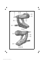
3.1 Overview of the product 1
@Fastener guide
;Slider for fastener driving depth adjustment
and for releasing the fastener guide
=RESET button
%Inlet/outlet valve
&Cooling air slots
(Belt hook
)Trigger
+Grip
§Nail pusher
/Magazine lockbutton
:Support leg
∙Magazine
$Type identification plate
£Gas can status indicator
|GAS button
¡Gas can compartment
QGas can compartment cover
3.2 Intended use
The product described is a gas-actuated fastening tool (“fastening tool”). It is designed to drive suitable
fasteners into concrete, steel, sand-lime block, concrete-block masonry, rendered masonry and other
materials suitable for use of the direct fastening technique.
The fastening tool is for hand-held use or use with the pole tool extension (accessory) only.
3.3 Items supplied
Gas-actuated fastening tool with fastener guide, toolbox, operating instructions.
Other system products approved for use with this product can be found at your local Hilti Center or online
at: www.hilti.group
3.4 Fastener guide
The fastener guide holds the studs or, respectively, guides the nails and, when the tool is fired, thus directs the
fasteners into the supporting material at the desired position. Application-specific fastener guides (IF or ME)
are available for the GX 3 and GX 3-ME fastening tools (see type identification plate for exact designation).
3.5 Fasteners
Two types of fastener can be driven by the fastening tool: nails and threaded studs. Additional fastening
components, which can be inserted in the fastener guide, are also available for various applications.
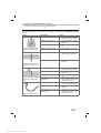
3.6 Slider for fastener driving depth adjustment and for releasing the fastener guide
The slider can be used to reduce the depth to which the fastener is driven. In the EJECT position, it releases
the fastener guide for removal.
Status Meaning
+• Standard fastener driving depth
• Reduced fastener driving depth
EJECT • Fastener guide release
Printed: 06.11.2018 | Doc-Nr: PUB / 5261692 / 000 / 01

English 5
3.7 RESET button
After driving a fastener, under certain circumstances, the fastener guide may not return to its outset position.
This is caused by the piston being incorrectly positioned. The incorrect piston position can be remedied by
pressing the RESET button.
Status Meaning
RESET button projects from the tool casing. Its
white edge is visible. • Piston position is incorrect
RESET button is flush with the tool casing. • Piston position is correct
3.8 Support leg
On an even working surface, the support leg makes it easier to hold the fastening tool perpendicular as
attention then only has to be paid to lateral alignment. On an uneven or undulating surface it may be necessary
to remove the support leg in order to allow the fastener guide to be held perpendicular to the working surface.
3.9 Belt hook
The belt hook can be extended in two stages.
Status Meaning
First position • Position for attaching to a waist belt
Second position • Position for attaching to ladders, scaffolds,
platforms, etc.
3.10 Gas can
Note
Observe the safety instructions provided with the gas can!
In order to operate the fastening tool, the gas can must be inserted in the gas can compartment.
The gas can status can be read from the LED display after pressing the GAS button.
The gas can must be removed before breaks between working, before maintenance and before transporting
or storing the fastening tool.
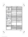
3.11 Indication of gas can status
After pressing the GAS button, the LED display indicates the status of the gas can.
Note
The gas level indicator does not operate correctly if the fastener guide / tool nosepeice has been fully
compressed.
Status Meaning
All four LEDs light green. • Level is approx. 100 %.
Three LEDs light green. • Level is approx. 75 %.
Two LEDs light green. • Level is approx. 50 %.
One LED lights green. • Level is approx. 25 %.
One LED blinks green. • Level is below 10 %. Replacement of the gas
can is recommended.
One LED lights red. • There is either no gas can in the fastening tool,
the wrong type of gas can is fitted or the can is
empty.
Note
Even when the level is indicated as “empty”, the gas can, for technical reasons, still contains a little gas.
Printed: 06.11.2018 | Doc-Nr: PUB / 5261692 / 000 / 01

6 English
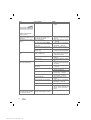
4 Technical data
4.1 Fastening tool
Weight (empty) 8.6 lb
(3.9 kg)
Application temperature, ambient temperature 14 ℉ …113 ℉
(−10 ℃ …45 ℃)
Maximum fastener length 1.5 in
(39 mm)
Fastener diameter • 0.10 in (2.6 mm)
• 0.12 in (3.0 mm)
Compression stroke 1.6 in
(40 mm)
Magazine capacity 40 + 2 nails
Maximum fastener driving frequency (Fasteners per hour) 1,200
Maximum magnetic field strength −16.5 dBµA/m
Frequency 13,553 MHz …13,567 MHz
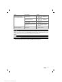
4.2 Noise information and vibration values
The sound pressure and vibration values given in these instructions have been measured in accordance
with a standardized test and may be used to compare one fastening tool with another. They may be used
for a preliminary assessment of exposure. The data given represents the main applications of the fastening
tool. However, if the fastening tool is used for different applications, with different accessories or is poorly
maintained, the data may vary. This may significantly increase exposure over the total working period. An
estimation of the level of exposure should also take into account the periods of time when the tool is not
actually in use. This may significantly reduce exposure over the total working period. Prescribe additional
safety measures to protect the operator from the effects of noise and/or vibration, such as: maintenance of
the direct fastening tool and its additional equipment or accessories, keeping the hands warm, organization
of work patterns.
Noise emission values determined in accordance with EN 15895
Emission sound pressure level at the workplace (LpA, 1s)99 dB(A)
Peak sound pressure level at the workplace (LpC, peak)133 dB (C)
Sound (power) level (LWA)105 dB(A)
Sound level uncertainty 2 dB(A) / 2 dB(C)
Recoil
Energy-equivalent acceleration, (ahw, RMS(3))Applicable to 1 mm sheet metal
on B35 concrete: 3.64 m/s2
Measurement uncertainty 0.13 m/s²
5 Loading the fastening tool
5.1 Loading for driving nails
5.1.1 Equipment required for driving nails
Nails are fed through the magazine in strip form (ready-to-use strips of nails).
Note
When driving nails there must be no single-fastener adapter present in the tool .
5.1.2 Loading the magazine
1. Pull the nail pusher back until it engages.
Printed: 06.11.2018 | Doc-Nr: PUB / 5261692 / 000 / 01

English 7
2. Slide the nail strips into the magazine as far as they will go.
Note
Strips of short nails could be inadvertently inserted the wrong way round. With short nails, take
care to ensure that the tips of the nails point towards the nose of the tool.
WARNING
Risk of finger injury! Fingers could be pinched when the nail pusher is released.
▶When disengaging the nail pusher, do not release it and allow it to jump forward. Guide it forward
slowly as far as it will go.
3. Release the nail pusher and guide it forward as far as it will go.
5.1.3 Inserting the gas can
1. Open the gas can compartment cover.
2. Remove the cap from the gas can.
Note
Keep the cap so that it can be used to close the gas can securely when it is removed from the
tool, e.g. when unloading and for transport.
3. Slide the gas can into the gas can compartment, valve first, so that the gas can clip enters the opening
for the clip and engages securely.
4. Close the gas can compartment cover.
5. Without pulling the trigger, firmly press the setting tool with the fastener guide three times against the
base material in order to bleed the gas lines of air.
5.2 Loading for driving threaded studs
5.2.1 Equipment required for driving threaded studs
Threaded studs must be inserted singly in the fastener guide from the front. An adapter is required for driving
single fasteners. The packaging units for threaded studs each contain an adapter for individual setting, with
the corresponding fitting information.
Note
In order to drive threaded studs, the magazine must first be emptied and an adapter for driving single
fasteners inserted.
5.2.2 Inserting the single-fastener adapter
▶Insert the single-fastener adapter ( → page 9).
5.2.3 Inserting the gas can
▶Insert the gas can ( → page 7).
6 Driving fasteners
6.1 Driving nails
WARNING
Risk of injury! Pressing the nosepiece of the fastening tool against a part of the body may lead to
serious injury due to inadvertent firing and release of a fastener.
▶Never press the nosepiece of the tool against your hand or any other part of the body.
1. Check the fastener driving depth setting.
2. Bring the nosepiece of the setting tool and the support leg into contact with the working surface.
3. Using the fastener guide, press the setting tool as far as it will go against the base material.
4. Check that the fastener guide is perpendicular to the working surface.
Printed: 06.11.2018 | Doc-Nr: PUB / 5261692 / 000 / 01

8 English
5. Pull the trigger to drive a fastener.
Note
It is not possible to drive a fastener if the fastener guide is not pressed fully against the working
surface.
6. Lift the fastening tool completely away from the working surface after driving a fastener.
7. Remove the gas can ( → page 8) and empty the magazine ( → page 8) when work with the setting tool is
finished or before leaving the tool unattended.
6.2 Driving threaded studs
WARNING
Risk of injury! Pressing the nosepiece of the setting tool against a part of the body may lead to
serious injury due to inadvertent firing and release of a fastener.
▶When inserting fasteners, on no occasion press the fastener guide against a hand or any
other part of the body.
▶Never press the nosepiece of the tool against your hand or any other part of the body.
WARNING
Risk of injury by falling objects! Triggering the tool again on top of a nail or stud that was not
optimally driven may weaken the fastening. The object that was fastened may fall down as a result,
causing damage or injury.
▶Never trigger the tool again in an attempt to improve the hold of a previously driven nail or
stud.
1. Check the fastener driving depth setting.
2. Insert a stud in the fastener guide.
3. Bring the nosepiece of the setting tool and the support leg into contact with the working surface.
4. Using the fastener guide, press the setting tool as far as it will go against the base material.
5. Check that the fastener guide is perpendicular to the working surface.
6. Pull the trigger to drive a fastener.
Note
It is not possible to drive a fastener if the fastener guide is not pressed fully against the working
surface.
7. Remove the gas can when work with the setting tool is finished or before leaving the tool unattended
( → page 8).
7 Unloading the fastening tool
7.1 Removing the gas can
1. Open the gas can compartment cover.
2. Press the gas can clip to release the gas can.
3. Remove the gas can from the gas can compartment.
4. Fit the cap on the gas can.
5. Close the gas can compartment cover.
7.2 Unloading the magazine
1. Pull the nail pusher back until it engages.
2. Remove all nail strips from the magazine.
WARNING
Risk of finger injury! Fingers could be pinched when the nail pusher is released.
▶When disengaging the nail pusher, do not release it and allow it to jump forward. Guide it forward
slowly as far as it will go.
3. Release the nail pusher and guide it forward as far as it will go.
Printed: 06.11.2018 | Doc-Nr: PUB / 5261692 / 000 / 01

English 9
7.3 Removing the single-fastener adapter
▶After driving the fasteners, remove the single-fastener adapter ( → page 10) from the fastening tool.
8 Optional operating steps
8.1 Checking the status of the gas can
1. Without pressing the fastening tool against the working surface, press the GAS button.
2. Read the gas can status from the display. → page 5
8.2 Removing the magazine
1. Pull the nail pusher back until it engages.
2. Remove the loose nail strips from the magazine.
WARNING
Risk of finger injury! Fingers could be pinched when the nail pusher is released.
▶When disengaging the nail pusher, do not release it and allow it to jump forward. Guide it forward
slowly as far as it will go.
3. Release the nail pusher and guide it forward as far as it will go.
4. Release the magazine locking catch.
5. Pivot the magazine about the pivot point towards the front.
6. Detach the magazine.
8.3 Fitting the magazine
1. Release the magazine locking catch.
2. Engage the front end of the magazine with the setting tool.
3. Pivot the magazine towards the setting tool as far as it will go.
4. Close the magazine locking catch.
8.4 Removing the fastener guide
1. Remove the gas can. → page 8
2. Move the fastener guide release slider to the EJECT position.
3. Remove the fastener guide.
8.5 Inserting the fastener guide
1. Remove the gas can. → page 8
2. Slide the fastener guide into the slot in the nose of the fastening tool.
3. Hold the fastener guide securely so that it cannot fall out and then press the nose of the tool (i.e. the tool
with the fastener guide) against a firm surface until the fastener guide engages.
4. Check that the fastener guide has engaged.
◁Once the fastener guide has engaged, the slider for releasing the fastener guide is again in the +
position.
8.6 Removing the support leg
1. Release the support leg engaging mechanism by pressing lightly.
2. Rotate the support leg through 90°.
3. Remove the support leg.
8.7 Fitting the support leg
1. Bring the support leg into contact with the magazine at right angles and guide it into the slot.
2. Rotate the support leg through 90° relative to the magazine and allow it to engage while applying light
pressure.
8.8 Inserting the single-fastener adapter
1. Remove the gas can. → page 8
2. Remove the magazine. → page 9
Printed: 06.11.2018 | Doc-Nr: PUB / 5261692 / 000 / 01

10 English
3. Insert the single-fastener adapter.
4. Fit the magazine. → page 9
8.9 Removing the single-fastener adapter
1. Remove the gas can. → page 8
2. Remove the magazine. → page 9
3. Remove the single-fastener adapter.
4. Fit the magazine. → page 9
9 Remedying possible malfunctions
9.1 Remedying an incorrect piston position
▶Check the position of the RESET → page 5 button.
Result
•RESET button projects from the tool casing. Its white edge is visible.
▶To remedy the incorrect piston position, press the RESET button.
9.2 Removing foreign objects and nails from the area around the fastener guide
CAUTION
Risk of injury by flying parts! Triggering the tool (attempting to drive a fastener) when foreign objects
are present in the area around the fastener guide, or when a fastener is jammed in the fastener guide,
may lead to injury caused by flying objects or fragments.
▶Never attempt to remedy tool malfunctions by continuing to trigger the tool!
1. Remove the gas can. → page 8
2. Unload the magazine. → page 8
3. Remove the magazine. → page 9
4. Remove the fastener guide. → page 9
5. Remove all foreign objects and nails from the area around the fastener guide.
6. Insert the fastener guide. → page 9
7. Fit the magazine. → page 9
10 Care and maintenance
10.1 Caring for the fastening tool
▶Never operate the fastening tool if the cooling air slots are blocked.
▶Keep the grip areas free from oil and grease.
▶Clean the fastening tool regularly. → page 10
▶Do not use spray devices, pressure jet washers or running water for cleaning.
▶Do not use cleaning agents containing silicone.
▶Do not use sprays or similar lubricating and cleaning agents.
10.2 Cleaning the fastening tool
1. Remove the gas can. → page 8
2. Unload the magazine. → page 8
3. Remove plastic fragments from the fastener guide.
4. Use a dry brush to clean the cooling air slots, taking care to prevent dirt or foreign objects entering the
interior of the tool.
5. Use a damp cloth to clean the exterior of the tool.
Printed: 06.11.2018 | Doc-Nr: PUB / 5261692 / 000 / 01

English 11
11 Transport and storage
11.1 Maintenance
▶To help ensure safe and reliable operation, use only genuine Hilti spare parts and consumables. Spare
parts, consumables and accessories approved by Hilti for use with the product can be found at your
local Hilti Center or online at: www.hilti.group.
▶Check all external parts of the fastening tool for signs of damage at regular intervals and make sure that
all the controls function correctly.
▶Do not use the fastening tool if parts are damaged or if the controls do not function correctly.
▶Have a defective fastening tool repaired by Hilti Service.
11.2 Checks after care and maintenance work
▶Move the fastener driving depth adjustment slider to the +position.
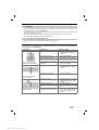
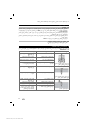
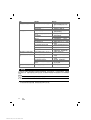
12 Troubleshooting
If the trouble you are experiencing is not listed in this table or you are unable to remedy the problem by
yourself, please contact Hilti Service.
Malfunction Possible cause Action to be taken
Fasteners are frequently
driven to inadequate depth.
Driving power is too low. ▶Move the fastener driving depth
adjustment slider to the +
position.
The fasteners are too long. ▶Use shorter fasteners.
The supporting material is too
hard.
▶Consider using a DX fastening
tool.
The inlet/outlet valve is clogged or
covered over.
▶Clean the fastening tool and
check how it is held.
Fasteners are frequently
driven too deeply.
Driving power is too high. ▶Move the fastener driving depth
adjustment slider to the ‒
position.
The fasteners are too short. ▶Use longer fasteners.
Fasteners break.
Driving power is too low. ▶Move the fastener driving depth
adjustment slider to the +
position.
The fasteners are too long. ▶Use shorter fasteners.
The supporting material is too
hard.
▶Consider using a DX fastening
tool.
The fastener guide is not held per-
pendicular to the working surface.
▶Press the nosepiece against
the working surface, keeping
the tool perpendicular to the
surface.
Printed: 06.11.2018 | Doc-Nr: PUB / 5261692 / 000 / 01

12 English
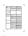
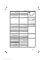
Malfunction Possible cause Action to be taken
Fasteners bend.
Driving power is too low. ▶Move the fastener driving depth
adjustment slider to the +
position.
The fasteners are too long. ▶Use shorter fasteners.
The fastener guide is not held per-
pendicular to the working surface.
▶Press the nosepiece against
the working surface, keeping
the tool perpendicular to the
surface.
Fasteners do not hold in steel
base material.
The supporting material is too thin. ▶Use a different fastening
method.
The content of the gas can is
inadequate for the number of
fasteners in the package.
High gas consumption due to fre-
quent compression of the tool
nosepiece without driving a fas-
tener.
▶Avoid compressing the tool
nosepiece without driving a
fastener.
The tool remains compressed
(nose does not extend when
pressure is released).
Incorrect piston position. ▶Remedy the incorrect piston
position. → page 10
The nail detector is jammed and
the RESET button is not flush with
the casing when pressed.
▶Remove foreign objects and
nails from the area around the
fastener guide. → page 10
A fastener has jammed in the fas-
tener magazine.
▶Release the jammed fastener.
A nail is jammed under the lever
ahead of the piston face.
▶Remove the gas can, press
the tool nosepeice against the
working surface and pull the
trigger firmly.
Fastener driving failure rate is
too high. The fastener magazine is not held
perpendicular to the working sur-
face.
▶Press the nosepiece against the
working surface, keeping the
fastener guide perpendicular to
the surface.
Wrong type of fastener used. ▶Use a suitable type of fastener.
The supporting material is too
hard.
▶Consider using a DX fastening
tool.
No fastener is driven. The nail pusher was not moved
forward.
▶Release the nail pusher and
guide it forward as far as it will
go.
Insufficient nails in the magazine (2
nails or fewer).
▶Load the magazine. → page 6
Nail transport malfunction. ▶Use a different nail strip.
▶Clean the magazine.
Gas can is empty. ▶Check the status of the gas can.
→ page 9
LED 1 lights red ▶Check the status of the gas can.
→ page 9
Air in the gas lines ▶Press the setting tool three
times in position without pulling
the trigger.
Printed: 06.11.2018 | Doc-Nr: PUB / 5261692 / 000 / 01

English 13
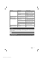
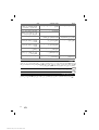
Malfunction Possible cause Action to be taken
No fastener is driven. Foreign object in the area of the
fastener guide
▶Remove foreign objects and
nails from the area around the
fastener guide. → page 10
The fastening tool is too hot. ▶Allow the fastening tool to cool
down.
Electronic fault. ▶Remove the gas can and then
reinsert it. If the problem
persists, use a new gas can.
The fastening tool is hot and
doesn’t work even after a
break.
The fastener driving rate was well
above 1,200 fastenings per hour.
▶Allow the fastening tool to cool
down.
No fastener is driven (or
driven only intermittently). Ambient conditions are outside the
permissible range.
▶Make sure that the permissible
ranges, in accordance with the
technical data, are observed.
The gas can temperature is outside
the permissible range.
▶Make sure that the permissible
ranges, in accordance with the
technical data, are observed.
Gas bubbles have formed in the
gas regulating system.
▶Remove the gas can and then
reinsert it.
The tool was not lifted completely
away from the surface after driving
a fastener.
▶Lift the fastening tool completely
away from the working surface
after driving a fastener.
A fastener cannot be
removed from the fastener
guide.
A fastener has jammed in the fas-
tener magazine.
▶Release the jammed fastener.
13 Disposal
Most of the materials from which Hilti tools and appliances are manufactured can be recycled. The
materials must be correctly separated before they can be recycled. In many countries, your old tools,
machines or appliances can be returned to Hilti for recycling. Ask Hilti Service or your Hilti representative
for further information.
▶Disposal of electric tools or appliances together with household waste is not permissible.
14 Manufacturer’s warranty
▶Please contact your local Hilti representative if you have questions about the warranty conditions.
Printed: 06.11.2018 | Doc-Nr: PUB / 5261692 / 000 / 01

14 Français
1 Indications relatives à la documentation
1.1 À propos de cette documentation
• Lire intégralement la présente documentation avant la mise en service. C'est la condition préalablement
requise pour assurer la sécurité du travail et un maniement sans perturbations.
• Bien respecter les consignes de sécurité et les avertissements de la présente documentation ainsi que
celles figurant sur le produit.
• Toujours conserver le mode d'emploi à proximité du produit et uniquement le transmettre à des tiers
avec ce mode d'emploi.
1.2 Explication des symboles
1.2.1 Avertissements
Les avertissements attirent l'attention sur des dangers liés à l'utilisation du produit. Les termes de
signalisation suivants sont utilisés en combinaison avec un symbole :
DANGER ! Pour un danger imminent qui peut entraîner de graves blessures corporelles ou la
mort.
AVERTISSEMENT ! Pour un danger imminent potentiel qui peut entraîner de graves blessures
corporelles ou la mort.
ATTENTION ! Pour attirer l'attention sur une situation pouvant présenter des dangers entraînant
des blessures corporelles légères ou des dégâts matériels.
1.2.2 Symboles dans la documentation
Les symboles suivants sont utilisés dans la présente documentation :
Lire le mode d'emploi avant d'utiliser l'appareil
Pour des conseils d'utilisation et autres informations utiles
1.2.3 Symboles dans les illustrations
Les symboles suivants sont utilisés dans les illustrations :
Ces chiffres renvoient à l'illustration correspondante au début du présent mode d'emploi.
La numérotation détermine la séquence des étapes de travail dans l'image et peut se différencier
de celles des étapes de travail dans le texte.
Les numéros de position sont utilisés dans l'illustration Vue d’ensemble et renvoient aux numé-
ros des légendes dans la section Vue d'ensemble du produit.
Ce signe doit inviter à manier le produit en faisant particulièrement attention.
1.3 Symboles spécifiques au produit
1.3.1 Symboles sur le produit
Les symboles suivants sont utilisés sur le produit :
Symboles d'obligation généraux
Porter des lunettes de protection
Porter un casque antibruit
Porter un casque de protection
Recycler les déchets
Printed: 06.11.2018 | Doc-Nr: PUB / 5261692 / 000 / 01

Français 15
1.4 Identifications des textes
1.4.1 Mise en évidence de portions de texte
Les désignations et inscriptions sont mises en évidence comme suit :
‚ ‛ Désignation des organes de commande pourvus d'une inscription sur le cloueur.
« » Inscriptions sur le cloueur
1.5 Informations produit
Les produits Hilti sont conçus pour les utilisateurs professionnels et ne doivent être utilisés, entretenus et
réparés que par un personnel agréé et formé à cet effet. Ce personnel doit être au courant des dangers
inhérents à l'utilisation de l'appareil. Le produit et ses accessoires peuvent s'avérer dangereux s'ils sont
utilisés de manière incorrecte par un personnel non qualifié ou de manière non conforme à l'usage prévu.
La désignation du modèle et le numéro de série figurent sur sa plaque signalétique.
▶Inscrivez le numéro de série dans le tableau suivant. Les informations produit vous seront demandées
lorsque vous contactez nos revendeurs ou services après-vente.
Caractéristiques produit
Cloueur à gaz GX 3
Génération 01
N° de série
1.6 Déclaration de conformité
Nous déclarons sous notre seule et unique responsabilité que le produit décrit ici est conforme aux
directives et normes en vigueur. Une copie de la Déclaration de conformité se trouve en fin de la présente
documentation.
Pour obtenir les documentations techniques, s'adresser à :
Hilti Entwicklungsgesellschaft mbH | Zulassung Geräte | Hiltistraße 6 | 86916 Kaufering, DE
2 Sécurité
2.1 Consignes de sécurité
Travail en toute sécurité avec le cloueur
▶Si le cloueur est appuyé contre une partie du corps, un déclenchement d'un tir par mégarde peut
entraîner de graves blessures. Ne jamais appuyer le cloueur contre la main ou contre toute autre
partie du corps.
▶Lors du montage des fixations spécifiques aux applications sur le canon (p. ex. rondelles, colliers de
fixation, attaches, etc.), un déclenchement d'un tir par mégarde peut entraîner de graves blessures. Ne
jamais appuyer une main ou une partie du corps contre le canon lors du montage des fixations
spécifiques aux applications sur le canon.
▶Ne jamais diriger le cloueur vers soi ou vers une autre personne.
▶Lors du maniement du cloueur, garder les bras fléchis (ne pas tendre les bras).
▶Restez vigilant, surveillez ce que vous faites. Faites preuve de bon sens en utilisant le cloueur.
N'utilisez pas le cloueur si vous êtes fatigué ou après avoir consommé de l'alcool, des drogues ou
avoir pris des médicaments. Un moment d'inattention lors de l'utilisation du cloueur peut entraîner de
graves blessures.
▶Lors du retrait du poussoir à clous, toujours veiller à ce qu'il s'encliquette.
▶Lors du déblocage de l'enclenchement de sécurité, guider le poussoir à clous vers l'avant afin
d'éviter qu'il ne se dégage trop rapidement. L'utilisateur risque de se coincer les doigts.
▶Ne pas implanter d'éléments de fixation dans un matériau support trop dur, comme de l'acier soudé
ou de l'acier coulé. Une implantation dans ces matériaux peut entraîner des ratés de tir ou rendre les
éléments de fixation cassants.
▶Ne pas implanter d'éléments de fixation dans un matériau support trop mou, comme du bois ou du
placoplâtre. Une implantation dans ces matériaux peut entraîner des ratés de tir et des perforations du
matériau support.
▶Ne pas implanter d'éléments de fixation dans un matériau support trop fragile, comme du verre ou du
carrelage. Une implantation dans ces matériaux peut entraîner des ratés de tir et une projection d'éclats
du matériau support.
Printed: 06.11.2018 | Doc-Nr: PUB / 5261692 / 000 / 01

16 Français
▶Avant d'implanter, vérifier qu'il n'y ait aucun risque de blesser une personne ou d'endommager des
objets à l'arrière du matériau support.
▶Actionner la détente uniquement lorsque le cloueur est complètement appuyé contre le matériau support,
de telle sorte que le canon rentre jusqu'en butée dans le cloueur.
▶Porter impérativement des gants de protection lorsque des opérations d'entretien doivent être
effectuées sur un cloueur chaud.
▶En cas de cadences de tir élevées pendant une période prolongée, les surfaces hors de la partie
préhensible risquent de devenir brûlantes. Porter des gants de protection contre les brûlures.
▶En cas de surchauffe du cloueur, retirer la cartouche de gaz et laisser le cloueur refroidir. Ne pas
dépasser la cadence de tir maximale.
▶Pendant le tir, le matériau peut s'écailler ou des fragments du matériau de bande-chargeur peuvent
être projetés. Les éclats de matière peuvent entraîner des blessures corporelles et aux yeux. Utiliser
des lunettes de protection, un casque antibruit et un casque de protection appropriés. Le fait
de porter des équipements de protection personnels tels que masque anti-poussières, chaussures de
sécurité antidérapantes, casque de protection ou des lunettes de protection et une protection acoustique
appropriées, suivant le travail à effectuer, réduit le risque de blessures. Les autres personnes se trouvant
à proximité doivent également porter des lunettes de protection et un casque de protection.
▶Porter un casque antibruit approprié (voir les données d'émissions acoustiques dans les caractéristiques
techniques). L'implantation des éléments de fixation est déclenchée par la mise à feu d'un mélange
air-gaz. Les nuisances sonores ainsi générées peuvent entraîner une perte d'acuité auditive. Même les
personnes environnantes doivent porter un casque antibruit approprié.
▶Toujours maintenir le cloueur fermement et perpendiculairement au matériau support pour déclencher
un tir. Cela contribue à ce que l'élément de fixation ne soit pas dévié du matériau support.
▶Ne jamais implanter un deuxième élément de fixation au même endroit. Cela risque de rendre les
éléments de fixation cassants et de les coincer.
▶Ne jamais implanter un goujon ou un clou une deuxième fois. En cas de réutilisation, il y a risque de
casse des éléments de fixation ou de blessures.
▶Toujours retirer la cartouche de gaz ( → Page 21) et vider le chargeur ( → Page 21) avant de remplacer le
chargeur, de procéder aux travaux de nettoyage, de service et d'entretien, ainsi qu'avant le stockage et
le transport, ou si le cloueur est laissé sans surveillance.
▶Après utilisation, poser l'appareil à plat sur le sol. Un appareil installé au bout d'un prolongateur ou un
appareil posé contre un mur peut provoquer des blessures en tombant.
▶Lors de l'abaissement du cloueur, ne pas tenir par l'extrémité arrière l'appareil installé au bout d'un
prolongateur. Compte tenu de l'importante force de levier, il y a risque de perdre le contrôle du fait des
mouvements pivotants du cloueur. Ceci risque de provoquer des blessures ou des dommages matériels.
▶Vérifier que le cloueur et les accessoires ne sont pas endommagés, pour assurer un fonctionnement
sans défaillances et conforme à sa destination. Vérifier que toutes les pièces mobiles fonctionnent
parfaitement et ne coincent pas, et que les pièces ne sont pas abîmées. Toutes les pièces doivent être
montées correctement et remplir toutes les conditions propres à garantir le parfait fonctionnement du
cloueur. Les dispositifs de sécurité et les pièces endommagés doivent être réparés ou remplacés de
manière professionnelle par le S.A.V. Hilti , sauf indication contraire dans le mode d'emploi.
▶Ne faire réparer le cloueur que par un personnel qualifié et seulement avec des pièces de rechange
d'origine. Ceci permet d'assurer la sécurité du cloueur.
▶Toute manipulation ou modification du cloueur est interdite.
▶Ne pas utiliser le cloueur dans des endroits présentant un danger d'incendie ou d'explosion.
▶Prêter attention aux influences de l'environnement. Protéger le cloueur des intempéries, et ne pas
l'utiliser dans un environnement humide ou mouillé.
▶Utiliser le cloueur uniquement dans des emplacements bien aérés.
▶Utiliser les combinaisons de canon et d'éléments de fixation appropriées. Une combinaison erronée
risque d'endommager le cloueur ou de nuire à la qualité de la fixation.
▶Toujours respecter les consignes d'utilisation.
Risques liés au courant électrique
▶Avant d'entamer les travaux, contrôler l'espace de travail, p. ex. à l'aide d'un détecteur de métaux, afin
de vérifier l'absence de câbles ou gaines électriques, conduites de gaz ou d'eau cachés.
▶Tenir le cloueur uniquement par la poignée isolée s'il y a un risque lors des travaux de toucher des câbles
électriques cachés. Le contact avec un câble sous tension risque de mettre les parties métalliques de
l'appareil sous tension et de provoquer une décharge électrique.
Consignes quant au maniement du gaz utilisé
▶Respecter les consignes d'utilisation figurant sur la cartouche de gaz et les informations descriptives qui
l'accompagnent.
Printed: 06.11.2018 | Doc-Nr: PUB / 5261692 / 000 / 01
Sayfa yükleniyor ...
Sayfa yükleniyor ...
Sayfa yükleniyor ...
Sayfa yükleniyor ...
Sayfa yükleniyor ...
Sayfa yükleniyor ...
Sayfa yükleniyor ...
Sayfa yükleniyor ...
Sayfa yükleniyor ...
Sayfa yükleniyor ...
Sayfa yükleniyor ...
Sayfa yükleniyor ...
Sayfa yükleniyor ...
Sayfa yükleniyor ...
Sayfa yükleniyor ...
Sayfa yükleniyor ...
Sayfa yükleniyor ...
Sayfa yükleniyor ...
Sayfa yükleniyor ...
Sayfa yükleniyor ...
Sayfa yükleniyor ...
Sayfa yükleniyor ...
Sayfa yükleniyor ...
Sayfa yükleniyor ...
Sayfa yükleniyor ...
Sayfa yükleniyor ...
Sayfa yükleniyor ...
Sayfa yükleniyor ...
Sayfa yükleniyor ...
Sayfa yükleniyor ...
Sayfa yükleniyor ...
Sayfa yükleniyor ...
Sayfa yükleniyor ...
Sayfa yükleniyor ...
Sayfa yükleniyor ...
Sayfa yükleniyor ...
Sayfa yükleniyor ...
Sayfa yükleniyor ...
Sayfa yükleniyor ...
Sayfa yükleniyor ...
Sayfa yükleniyor ...
Sayfa yükleniyor ...
Sayfa yükleniyor ...
Sayfa yükleniyor ...
Sayfa yükleniyor ...
Sayfa yükleniyor ...
Sayfa yükleniyor ...
Sayfa yükleniyor ...
Sayfa yükleniyor ...
Sayfa yükleniyor ...
Sayfa yükleniyor ...
Sayfa yükleniyor ...
Sayfa yükleniyor ...
Sayfa yükleniyor ...
Sayfa yükleniyor ...
Sayfa yükleniyor ...
Sayfa yükleniyor ...
Sayfa yükleniyor ...
Sayfa yükleniyor ...
Sayfa yükleniyor ...
Sayfa yükleniyor ...
Sayfa yükleniyor ...
Sayfa yükleniyor ...
Sayfa yükleniyor ...
Sayfa yükleniyor ...
Sayfa yükleniyor ...
Sayfa yükleniyor ...
Sayfa yükleniyor ...
Sayfa yükleniyor ...
Sayfa yükleniyor ...
Sayfa yükleniyor ...
Sayfa yükleniyor ...
-
 1
1
-
 2
2
-
 3
3
-
 4
4
-
 5
5
-
 6
6
-
 7
7
-
 8
8
-
 9
9
-
 10
10
-
 11
11
-
 12
12
-
 13
13
-
 14
14
-
 15
15
-
 16
16
-
 17
17
-
 18
18
-
 19
19
-
 20
20
-
 21
21
-
 22
22
-
 23
23
-
 24
24
-
 25
25
-
 26
26
-
 27
27
-
 28
28
-
 29
29
-
 30
30
-
 31
31
-
 32
32
-
 33
33
-
 34
34
-
 35
35
-
 36
36
-
 37
37
-
 38
38
-
 39
39
-
 40
40
-
 41
41
-
 42
42
-
 43
43
-
 44
44
-
 45
45
-
 46
46
-
 47
47
-
 48
48
-
 49
49
-
 50
50
-
 51
51
-
 52
52
-
 53
53
-
 54
54
-
 55
55
-
 56
56
-
 57
57
-
 58
58
-
 59
59
-
 60
60
-
 61
61
-
 62
62
-
 63
63
-
 64
64
-
 65
65
-
 66
66
-
 67
67
-
 68
68
-
 69
69
-
 70
70
-
 71
71
-
 72
72
-
 73
73
-
 74
74
-
 75
75
-
 76
76
-
 77
77
-
 78
78
-
 79
79
-
 80
80
-
 81
81
-
 82
82
-
 83
83
-
 84
84
-
 85
85
-
 86
86
-
 87
87
-
 88
88
-
 89
89
-
 90
90
-
 91
91
-
 92
92


Hilti GX 3 Kullanım kılavuzu
- Kategori
- Elektrikli aletler
- Tip
- Kullanım kılavuzu
Diğer dillerde
- français: Hilti GX 3 Manuel utilisateur
- 日本語: Hilti GX 3 ユーザーマニュアル
İlgili Makaleler
-
Hilti GX 3 Kullanma talimatları
-
-
-
Hilti GX 120 Kullanma talimatları
-
-
-
-
-
Hilti GX 90-WF Kullanma talimatları