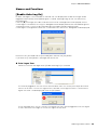
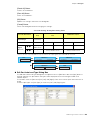
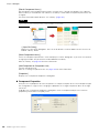
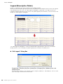
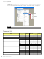
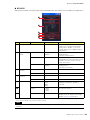
Yamaha v4 El kitabı
- Kategori
- Yazılım
- Tip
- El kitabı
Bu kılavuz aynı zamanda aşağıdakiler için de uygundur:

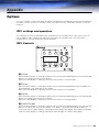
EN
OWNER’S MANUAL
OWNER’S MANUAL
Version 4.0
Version 4.0

DME Designer Owner’s Manual
2
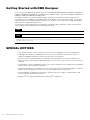
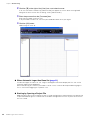
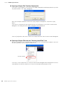
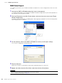
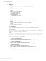
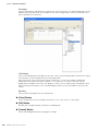
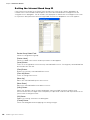
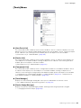
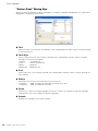
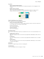
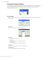
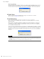
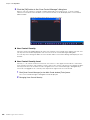
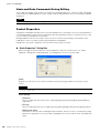
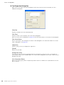
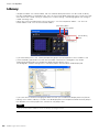
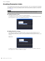
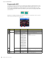
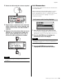
Getting Started with DME Designer
In this manual the abbreviation “DME” refers to the DME64N/DME24N/DME8i-C/DME8o-C/DME4io-C/
DME8i-ES/DME8o-ES/DME4io-ES. The abbreviation “DME Satellite” refers to the DME8i-C/DME8o-C/
DME4io-C/DME8i-ES/DME8o-ES/DME4io-ES.
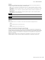
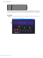
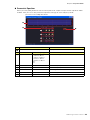
Your DME, SP2060, ICP1 and the DME Designer software, let you build a custom audio system
installation that can support an incredible variety of conditions. You can build an entire system from
input to output with the DME Designer software, then send the system data to the DME and SP2060
which become independent processors.
An amazing variety of applications are possible, including audio installations, sub-mixing, speaker
system control, matrix/routing, and multi-effect processing.
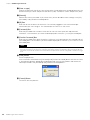
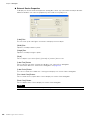
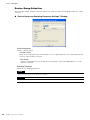
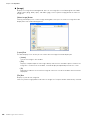
SPECIAL NOTICES
• The software and this Owner’s Manual are the exclusive copyrights of Yamaha Corporation.
• Copying of the software or reproduction of this manual in whole or in part by any means is
expressly forbidden without the written consent of the manufacturer.
• Yamaha makes no representations or warranties with regard to the use of the software and
documentation and cannot be held responsible for the results of the use of this manual and the
software.
• The company names and product names in this Owner’s Manual are the trademarks or registered
trademarks of their respective companies.
• The screen displays as illustrated in this Owner’s Manual are for instructional purposes, and may
appear somewhat different from the screens which appear on your computer.
• Future upgrades of application and system software and any changes in specifications and
functions will be announced separately.
•Windows
®
is the registered trademark of Microsoft
®
Corporation.
NOTE
Here the abbreviation “DME” does not include the “DME32.”
NOTE
This manual is based on the English version of operating system. Illustrations, command names, window names, and similar
information are from that version. Some items may differ from what you see on the computer screen, depending on which
operating system you are using.

DME Designer Owner’s Manual
3
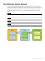
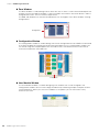
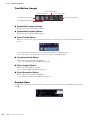
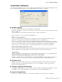
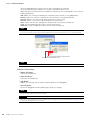
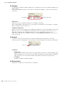
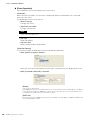
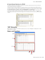
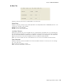
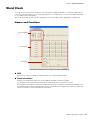
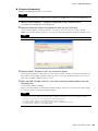
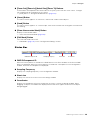
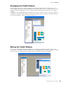
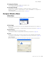
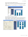
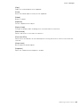
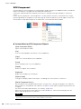
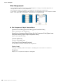
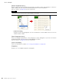
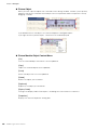
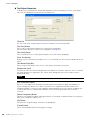
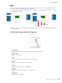
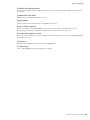
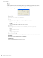
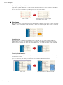
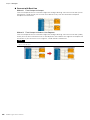
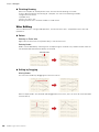
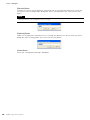
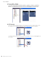
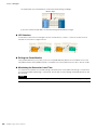
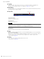
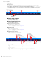
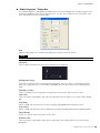
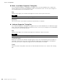
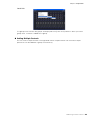
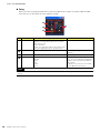
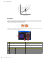
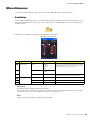
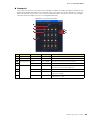
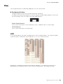
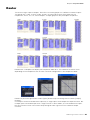
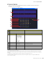
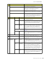
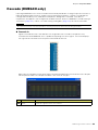
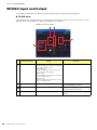
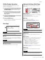
The DME Audio System Network
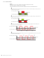
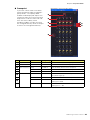
In an audio system including one or more DME units and/or SP2060 units, the “control space” is
logically organized using the concepts of “Area”, “Zone”, and “Device Group”. The space covered by
the entire system is the “Area”, while independent sonic spaces within that Area are called “Zone”.
A group of DME or SP2060 units assigned to the same function are considered a “Device Group”.
An Area is comprised of one or more Zones, and each Zone can include up to 32 Device Groups.
A single Device Group can include as many as 16 devices. Each Device Group has one “Group
Master”.
NOTE
Meter response may deteriorate as the number of meters displayed in a single device group in DME Designer increases. In
such cases meter response can be improved by dividing the device group.
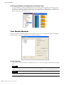
See “Zone Window” (page 298) for details on deleting devices from a device group.
NOTE
DME and SP2060 units cannot be combined in the same Device Group.
NOTE
All devices in a Device Group must be on the same subnet.
NOTE
A single device group cannot be controlled from multiple computers (multiple instances of DME Designer).
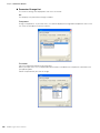
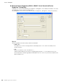
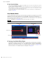
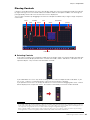
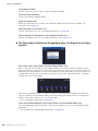
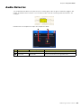
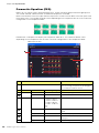
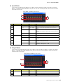
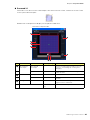
Area
Zone1
Zone2
Zone1
Device Group1
Device Group2
Device Group1
Device1
(Group Master)
Device2
(Slave)

DME Designer Owner’s Manual
4
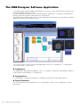
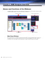
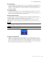
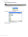
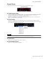
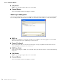
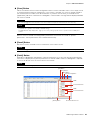
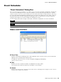
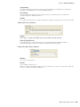
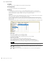
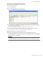
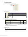
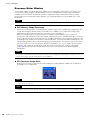
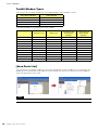
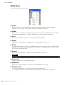
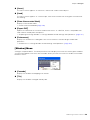
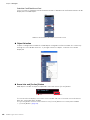
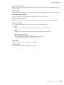
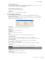
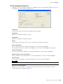
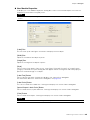
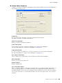
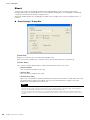
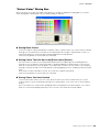
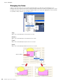
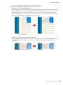
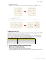
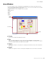
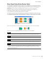
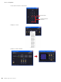
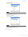
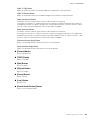
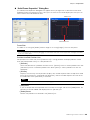
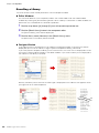
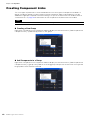
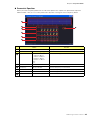
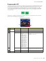
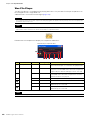
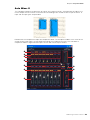
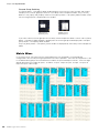
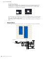
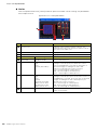
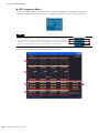
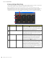
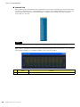
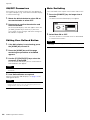
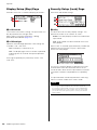
The DME Designer Software Application
The DME Designer software application provides a convenient, central interface for the creation and
control of DME-based audio systems.
By connecting the computer on which the DME Designer application is running to a Group Master it
becomes possible to control multiple devices simultaneously.
With DME Designer, DME audio systems can be designed and configured via a comprehensive block-
diagram interface on the computer screen.
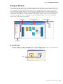
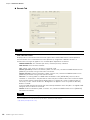
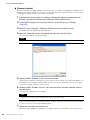
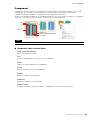
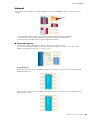
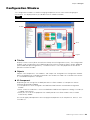
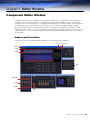
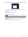
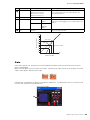
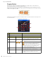
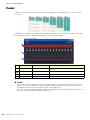
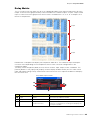
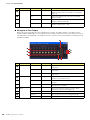
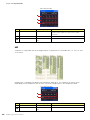
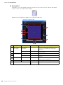
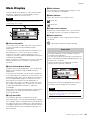
The main concepts used in the creation of DME audio systems are “Components”, “Configurations”,
“Preset Parameters”, and “Scenes”.
Components
Any independent signal-processing block, such as an equalizer, compressor, input/output module, or
external device control object is a “Component”.
Configurations
A “Configuration” is group of components, including their placement and interconnections.
Preset Parameters
The set of parameters for all components in a Configuration is know as the Configuration’s “Preset
Parameters”.

DME Designer Owner’s Manual
5
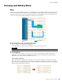
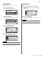
Scenes
A Configuration and its Preset Parameters are a “Scene”.
DME settings as well as Configuration and Preset Parameter settings are sent from the DME Designer
application running on the computer to the Device Master via USB or Ethernet, allowing each device
to function as a separate processor, independently from the computer. It is also possible to keep the
DME Designer application on line and control the devices in real time.
It is possible to use the DME Designer to create Configurations that include multiple devices when the
appropriate devices are connected.
Although it is possible to have multiple Zones in an Area, multiple Device Groups in a Zone, and
multiple Scenes and Configurations in a Device Group, only one Area, Zone, Device Group and
Configuration can be active and editable via the DME Designer at any one time. The active elements
are known as the Current Zone, Current Device Group, Current Scene, and Current Configuration.
Scenes1
Scenes2
Scenes
999
MATRIX MIXER
PARAMETRIC EQ
PARAMETRIC EQ
DELAY DELAYCROSSOVER
2WAY
COMP/LIMITER
PARAMETRIC EQ
DELAY CROSSOVER
2WAY
COMP/LIMITER
COMP/LIMITER GATE
PARAMETRIC EQ
DELAY COMP/LIMITER GATE
PARAMETRIC EQ
DELAY COMP/LIMITER GATE
PARAMETRIC EQ
DELAY COMP/LIMITER GATE
16 x 8
8 BAND
= Components
Example: GATE
• Attack
• Decay
• Range
• Threshold
• Key in
• Hold
Scenes
Composition of scene
Preset
Parameters
Configurations

DME Designer Owner’s Manual
6
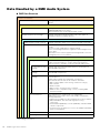
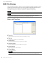
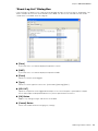
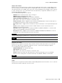
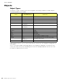
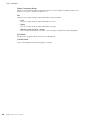
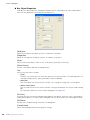
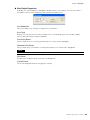
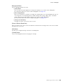
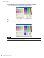
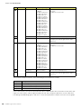
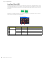
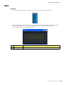
Data Handled by a DME Audio System
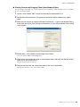
DME Data Structure
* Some settings not included.
Common Overall Data
Scene Link Settings Settings required for linked scene operation between multiple
groups.
Data for Each Device Group
User Defined Button Settings Settings required for component parameter control from the
DME64N/DME24N or ICP1 panel.
Up to 24 parameters can be registered for control.
Global Parameter Link Settings Settings required for linked operation of the same types of
parameters between multiple devices.
Data Used by the Scene Manager
MIDI program Change Settings Settings required to allow scene selection via MIDI commands.
Scenes The information required to switch audio data processing
setups.
Scenes include configurations and preset data.
The Scene Manager facilitates registration and management of
scene data.
Up to 999 scenes can be registered, and registered scenes are
managed by their scene numbers.
Data for Each Device
Configurations A combination of the audio signal processing, audio input/
output, and external device control components and their
interconnections, created to create the desired audio system.
Local Parameter Link
Settings
Settings that allow linked operation between similar types of
internal DME parameters.
Component Link
Settings
Settings that allow linked operation between similar types of
internal DME components.
External Device
Settings
Settings required to allow control of component parameters from
external devices.
Independent settings are required for each device.
The external devices that can be used are as follows:
• MIDI Controller (MIDI Control Change, Parameter Change).
•GPI Controller.
• DAW Controller.
• AMX, Crestron, and other remote controllers.
• PM5D or other compatible mixing console (controlling DME
internal head amp)
Preset Parameters The settings for the components in a configuration.
Audio processing setups can be switched by changing the
preset parameters.
Components included in the preset parameter set are as follows:
• GEQ, MatrixMixer, and other audio signal processing
components.
• Internal AD/DA (DME24N), Cascade (DME64N), and Mini-YGDAI
card I/O components*.
• Components for external devices such as the AD8HR and AD824
remote head amplifiers.
Wave file Audio files to be played back by the Wav File Player.
File Storage Project files and other file types can be stored.

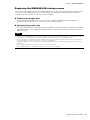
DME Designer Owner’s Manual
7
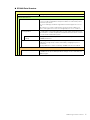
SP2060 Data Structure
Common Overall Data
Scene Link Settings Settings required for linked scene operation between multiple devices.
Data for Each Device
Scenes The information required to switch audio data processing setups.
Scenes include configurations and preset data, The last Library name
recalled is specified.
The Scene Manager facilitates registration and management of scene
data.
Up to 99 scenes can be registered for 12 preset areas and 87 user
areas, and registered scenes are managed by their scene numbers.
Configurations A combination of the audio signal processing, audio input/output, and
external device control components and their interconnections, created
to create the desired audio system.
Local Parameter Link
Settings
Settings that allow linked operation between similar types of internal
SP2060 parameters.
Preset Parameters The settings for the components in a configuration.
Audio processing setups can be switched by changing the preset
parameters.
Preset parameters can be recalled by SP2060 units, but not edited.
Data for Each Component
Library Settings specific to the speakers to be used.
In addition to the preset data provided, settings can be created by the
DME Designer.

DME Designer Owner’s Manual
8
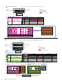
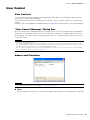
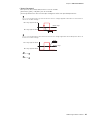
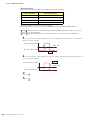
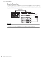
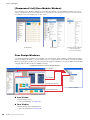
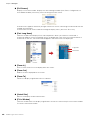
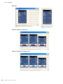
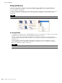
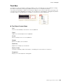
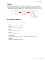
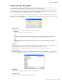
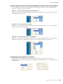
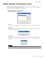
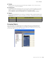
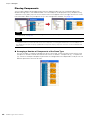
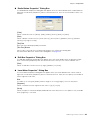
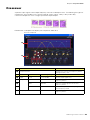
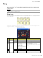
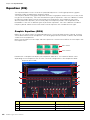
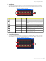
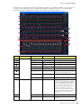
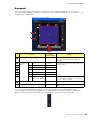
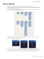
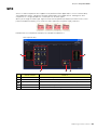
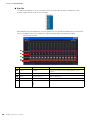
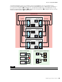
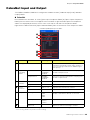
One DME unit/Device Group
No.
001
002
003
004
005
006
....
Configuration
Output Processor for Dome
Output Processor for Dome
Output Processor for Dome
Output Processor for Dome
Output Processor for Dome
...
Scene Name
All On
Opening
Band Set 1
Band Set 2
Band Set 3
...
Preset Parameters
All On
BGM & MC
Band 1
Band 2
Band 3
Microphone
Mixer
External Head Amp
etc...
Power Amp
Processor
etc...
Input
External Device (MIDI, GPI, DAW, AMX/Crestron, controlling DME internal head amp)
Audio signal
Notes
Device Group
Output
Control signal
Data explanation
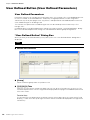
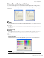
Setting preset parameters
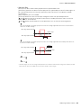
LCD Display
Dome Low
Dome Mid
Dome Hi
....
Assigned Parameter
Crossover: Output Low: Level
Crossover: Output Mid: Level
Crossover: Output High: Level
(No Assign)
(No Assign)
(No Assign)
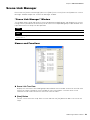
User Defined Button Scene Manager
Specifies the parameter to be changed.
Specifies the configuration
and preset parameters combination.
Configuration
Output Processor for Dome
Local parameter link settings
External device settings
MY8-AE
(Input)
MY8-AE
(Output)
Cross-
Over
EQ
Delay EQ Dyn
Delay
All On Component value
BGM & MC
Band 1
Band 2
Band 3
Preset parameters for output processor
Set the value
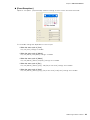
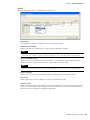
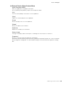
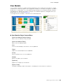
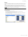
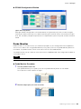
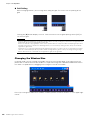
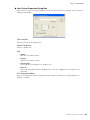
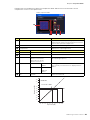
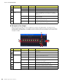
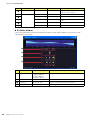
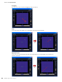
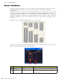
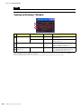
Two DME units/Device Group
(When one DME unit doesn’t provide sufficient processing power, up to 16 DME units can be used)
DME#2
Configuration
Output Processor
for Hall
Local parameter link settings
External device settings
All On
BGM & MC
Band
Device Group
LCD Display
Dome Low
Dome Mid
Dome Hi
Hall Low
Hall Mid
Hall Hi
....
Assigned Parameter
#1: Crossover: Output Low: Level
#1: Crossover: Output Mid: Level
#1
:
Crossover
:
Output High
:
Level
#2: Crossover: Output Low: Level
#2: Crossover: Output Mid: Level
#2
:
Crossover
:
Output High
:
Level
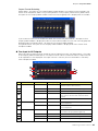
No.
001
002
003
004
005
006
....
Configuration
Output Processor for Dome
Output Processor for Dome
Output Processor for Dome
Output Processor for Dome
Output Processor for Dome
...
Scene Name
All On
Opening
Band Set 1
Band Set 2
Band Set 3
...
Preset parameters
All On
BGM & MC
Band 1
Band 2
Band 3
Configuration
Output Processor for Hall
Output Processor for Hall
Output Processor for Hall
Output Processor for Hall
Output Processor for Hall
...
Preset parameters
All On
BGM & MC
Band
Band
Band
User Defined Button
Scene Manager
DME#1
Configuration
Output Processor
for Dome
Local parameter link settings
External device settings
All On
BGM & MC
Band 1
Band 2
Band 3
Preset parameters Preset parameters
External Device (MIDI, GPI, DAW, AMX/Crestron, controlling DME internal head amp)
Microphone
Mixer
External Head Amp
etc...
Power Amp
Processor
etc...
Input Output
Input Output
DME#1
DME#2
For DME#2
For DME#1
Specifies the parameter to be linked between DME units.
Global Parameter Link
For DME#1 For DME#2
Audio signal
Notes
Control signal
Data explanation
Setting preset parameters
Selects the parameter to be
edited from two DME units.
Specifies the configuration and preset
data combination in each DME


DME Designer Owner’s Manual
10
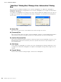
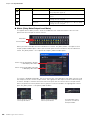
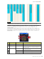
Main Changes from V1.0 to V1.1
Main Panel Window
• Instead of the former Parameter Link function, there are now two functions: a Global Link function
that links parameters within all DMEs in a zone and a Local Link function that links parameters
within a single DME unit. (page 94)
• The Synchronization function can now not only send data from DME Designer to the DME unit,
but can also synchronize by reading data from the DME unit. (page 97)
• Scene Increment/Decrement and Time Adjustment can now be assigned in the GPI input
function. (page 114)
• DME unit events can now be recorded by the Event Logger function and displayed in the Event
Logger window. (page 177)
• The time for executing an event can now be set by using the Event Scheduler function.
(page 139)
• Parameters in the current configuration can now be listed on the display and printed out by using
the Parameter List function. (page 144)
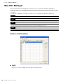
• The Wav File Manager can manage Wave files played by the Wav File Player. (page 151)
• Settings can be made by the DAW Control function that are used for controlling DMEs from a
DAW controller. (page 157)
• DME unit data can now be saved as a backup file by using the Backup function. (page 157)
Designer Window
• The port name display can now be switched between long name display and short name display.
(page 206)
• DME64N cascade connections can now be set. (page 221)
• Priority items can now be set when compiling configurations by using the [Compile Priority]
function in the “Preferences” dialog box. (page 220)
• Delay time can now be displayed for each component by using the Show Signal Delay function.
(page 305)
• Monitoring points can now be edited by using the “Monitoring Point List” dialog box. (page 306)
• The status of connections in a configuration can now be analyzed in advance by using the
Analyze function, without connecting the DME unit. (page 308)
• You can now set the action that occurs when you double-click a user module object. You can also
turn user module security ON or OFF, and set a password. (page 246)
• Libraries with component parameters saved in them can now be recalled from the context menu
for a component object. (page 236)
• A new rule for wiring prohibits connections to terminals that would short the terminator.
Component Editor/Component
• A status bar has been added to the component editor. It displays the component name,
component ID, and parameter IDs for parameters that are being edited. (page 320)
• A Snap function has been added that records parameters in the editor temporarily. Parameter
sets can then be switched by using the Snap buttons. (page 362)
• The meter’s peak hold function can now be turned ON or OFF. (page 359)
• A Wav File Player component has been added for playing Wave files. (page 430)
• An effect component called SPX has been added that supports many different effect
applications, such as reverb, delay, and modulation effects, along with complex combinations of
multiple effects. (page 471)
• A Slot Out component editor has been added. (page 488)
• An Undo/Redo function is now available when using the design mode. It can undo the most
recent operation (control movement/resize/deletion).

DME Designer Owner’s Manual
11
Changes from V1.1 to V1.2
Main Panel Window
• The synchronization algorithm has been refined for faster synchronization.
• Synchronization now can be executed from DME to DME Designer without any break in the
sound.
• In the following cases, synchronization can be executed from DME Designer to DME without any
break in the sound:
The second or later synchronization after starting DME Designer* and when differences in data
between the DME and DME Designer are limited to parameters within components, AD824/
AD8HR/DME24N AD/DA setting data, or Mini-YGDAI card setting parameters.
* If the file was saved when DME Designer was closed, there will be no break in sound even in the first
synchronization after saving.
• Compile speed has been increased.
Up to three times faster when AutoDelayCompensation is turned On.
Up to two times faster when AutoDelayCompensation is turned Off.
• Synchronization is possible when no Mini-YGDAI card or a different Mini-YGDAI card is installed
in the DME unit (a confirmation message will appear).
• An option to automatically close the dialog after synchronization has been added. (page 99)
• A progress bar has been added to the Synchronization dialog. (page 51)
• A message appears to warn when synchronization will cause muting.
• The following operations can be performed while on line:
- Scene storage.
- Scene name changes.
- Fade ON/OFF and Fade Mode changes.
- Fade time changes.
- Parameter link setting changes.
• When a scene store is executed, that scene becomes the current scene.
• Wave files can be saved as DME data files, and are included in import/export operations.
(page 44)
• Wave files can be saved in the Wav file library.
• Event Log events can be output via GPI. (page 79)
• The on-line indicator appears as a button which can be used to switch between on-line and
off-line. (page 59)
• Scene edits cause the EDIT indicator to appear. (page 57)
• An auto file save function (Auto Save, post synchronization) has been added. (page 73)
• Different zones can be specified for use by different users. (page 158)
• Scene parameters related to User Defined Button, Program Change, GPI In and GPI Out can be
set via the Scene Manager. (page 82)
• [Select All] and [Clear All] buttons have been added to the Scene Manager Recall Safe dialog
box. (page 86)
• User Control can be created for individual users as well as security levels. (page 91)
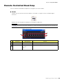
• A Remote Control Setup List has been added. (page 139)
This list can be used to make detailed settings for a new software protocol that allow the DME to
be controlled from AMX, Crestron, and similar devices.
Refer to the “DME-N Remote Control Protocol Specifications” document for details about the
communication protocol. Information about the “DME-N Remote Control Protocol Specifications”
document can be found at the Yamaha pro Audio website (URL below).
http://www.yamahaproaudio.com/
• It is possible to specify whether listed events will be executed by the Event Scheduler.
(page 139)

DME Designer Owner’s Manual
12
• The order of same-time events can be changed in the Event Scheduler. (page 139)
• Exceptions can be specified for Event Scheduler execution day/time. (page 107)
• Event Scheduler execution times can be specified in 1-second increments. (page 106)
• Head amp gain and Mini-YGDAI Card can be set via GPI, MIDI, User defined Button, DAW
Control.
• Parameter values, scene recall, GPI output, Wave file playback, and head amp gain can be set
via the User Defined Buttons. (page 132)
• The Component Lock function dialog is separate from the Parameter List dialog. (page 150)
• Shortcuts can be freely set as required. (page 156)
• Files can be saved in the DME unit. (page 70)
• A [Close All Editor Windows] button has been added to the Window menu. (page 69)
• External head amp parameters will be recognized by the DME unit when either the DME or the
external head amp (AD824, AD8HR) are turned on. Execute a scene recall to send DME settings
an external head amp.
• This manual is now separate from the DME Designer installer, and can not be accessed from the
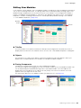
DME Designer menus.
Designer Window
• The following operations can be carried out via the shortcut keys.
- Navigator
- Activate Navigator
- Activate Toolkit
- Activate Design Window
- Select Left Port and Start Wiring
- Select Right Port and Start Wiring
- Wire Auto Single to Right
- Wire Auto Multi to Right
- Wire Auto Single to Left
- Wire Auto Multi to Left
- Delete Wire
• It is now possible to simultaneously edit multiple objects of the same type.
Example: Change the thickness or color of multiple wires at once.
• Files related to user modules (user module files, library files, user module editor files) can be
combined and exported/imported as a single file.
• Port colors can be independently specified for each port type. (page 219)
• Default wire thicknesses and types can be independently specified for each port type.
• An automatic hot-spot connection function has been added. (page 285)
• Port display has been added to External Device, Picture, DME, and ICP1 objects.
• When drawing wires the keyboard cursor keys can be used to move the mouse cursor, and the
<Enter> key can be used to create nodes.
• When drawing wires <Shift> key plus <> key and <Shift> key plus <> key combinations can
be used to automatically connect horizontally-aligned hot spots.
• DME object ports can be freely specified.
• Compilation of configurations with loop connections is possible when Auto Delay Compensation
is On.
• The name has been changed from “Foot Monitor” external device to “Floor Monitor.”
• Addition External Device types have been provided.
• External Devices can be double-clicked to open a file saved by other applications. (page 233)
• Picture objects can be double-clicked to open a specified editor. (page 249)
• Text objects can be double-clicked to open a specified editor. (page 252)

DME Designer Owner’s Manual
13
• User module port labels can be edited. (page 246)
• Graphics can be placed to represent user modules. (page 247)
• The Legend field automatically resizes to accommodate project names and titles of different
lengths.
• A Generic “MY-Others” setting has been provided to accommodate third-party Mini-YGDAI
cards.
Component Editor Window
• Undo and Redo are now shortcut compatible.
• A scroll bar appears when the size of the component editor window is reduced.
• The size and position of the component editor window are memorized.
• An option to allow mouse-over zooming of the edit box has been added. (page 323)
• A [Back] button that allows switching between related parent and child windows has been
added. (page 320)
• A [Close All Editor Windows] button has been added to the contextual menu.
• Source Selector, Speaker Processor, Limiter, Slot In, Cascade In, and Cascade Out components
have been added.
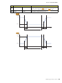
• The Delay algorithm has been revised. (page 399
- LEVEL and MUTE are effective when Delay is Off for each channel.
- The name of the overall Delay [On] parameter has been changed to [All Bypass].
• The bus send level range for Delay, Matrix, and Matrix Mixer components has been changed to
-∞ through 0.0 dB.
• Snap copy is possible. (page 363)
• Snap can be retained until the application is quit or another file is opened.
• Security status is displayed in the user module editor status bar.
• Multiple controllers can be selected by clicking while holding the <Ctrl> key when the editor is in
the design mode. (page 337)
• [Picture], [Text], [Box], [Ellipse], and [Frame] have been added to the tool palette of the user
module editor and user control editor design mode. (page 325)
• Controller properties can be accessed by double-clicking controllers in the user module editor or
user control editor design mode. (page 344)
• Picture and Text objects can be clicked to open a specified editor in the user module editor or
user control editor.
• The User Module Editor and User Control Editor offer a greater range of customization options for
color, size. etc., of the placed controls.
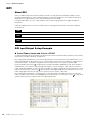
MIDI Setup
• A MIDI Setup minimize function has been added.
V1.2 Precautions
• When using project files (*.daf) created by version 1.1.5 or earlier, synchronize from the DME
Designer to the DME unit for the first synchronization.
• Project files (*.daf) created using version 1.2 will not open properly on version 1.1.
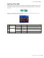
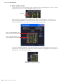
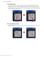
IN
Input
Mute
Input
Level
Input
Mute
Input
Level
On
Delay On
Delay All Bypass
OUT
OUT
Mute Level
On Mute Level
IN
Delay
Delay

DME Designer Owner’s Manual
14
Changes from V1.2 to V2.0
General
• Support added for DME8i-C/DME8o-C/DME4io-C, SP2060 units and MY16-CII.
• “Device Groups”, or groups of the same type of device, have been added at the lowest Zone
level.
• It is now possible to have one master device per device group rather than one master device per
zone. This means that it is possible to have multiple master devices in a single zone.
• Group masters can now be assigned regardless of the IP address. This makes it possible to have
multiple device groups at a single network address.
• Configurations can be created and deleted for each device group.
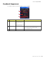
Component
• A Feedback Suppressor component has been added. (page 419)
• The Speaker Processor component PEQ “Q” parameter now goes to “63”. (page 464)
Main Panel Window
• Firmware and component data can now be updated simultaneously. (page 186)
• A Recovery Update function that allows recovery from program corruption has been added.
(page 188)
• A Component Link function that allows simultaneous linking of all component parameters has
been added. (page 94)
• Scene Link function that allows simultaneous control of multiple devices in different device
groups has been added. (page 151)
• A Protect function has been added to the scene manager. (page 82)
• Card settings are no longer included in scene data.
• A Utility window has been added to allow editing of device utility settings. (page 167)
• The Local Parameter Link display order has been changed. (page 94)
• Parameter Link operation can now be turned on or off for each device group. (page 94)
• Compilation and analysis is now possible even if no connections have been made.
• Navigator window hide/show can now be selected from the main window.
• The Event Logger can now display only the event data for a specified device. (page 75)
• The GPI terminal names have been changed from [CH] to [PORT].
Designer Window
• A hand tool for window movement has been added. The hand tool can be selected via the hand/
arrow icon in the toolbar, or from the [Tools] menu. The hand tool can also be temporarily
selected by holding the spacebar on your keyboard.
• Window magnification and reduction can now be controlled via the mouse wheel while holding
the keyboard “Ctrl” key.
• Horizontal scrolling can be controlled via the mouse wheel while holding the keyboard “Shift” key.
• The Edit Mode on/off can now be changed from the tool bar. (page 192)
• Scene information now appears in DME objects, and the Scene Manager can be launched from
the scene information display. (page 82)
• An [On-line] button has been added to DME objects, and synchronization is now possible.
(page 59)
• Sampling frequency display has been added to the resource meter window. (page 196)
• Sampling frequency display has been added to the configuration window status bar. (page 301)
• The sampling frequency is now displayed during analysis.

DME Designer Owner’s Manual
15
• Double-clicking the component name now opens the properties window.
• Organization of the Tool Kit window has been changed. (page 198)
• A [Draw Image] checkbox that displays or hides the worksheet background image file has been
added to the Sheet properties. (page 263)
• [Configuration Manager] has been added to the contextual menu that appears when a DME or
SP2060 object is right-clicked. (page 217,page 226)
• [Recall Component Library] and [Store Component Library] now appear in the contextual menu
that appears when a component is right-clicked, even when the Edit Mode is OFF.
• The Compile Settings can now be edited for each DME unit. (page 220)
• Only one Zone window is now provided for multiple configurations.
• The [Export DXF] and [Preferences] commands have been moved from the [Print] menu to the
[Tools] menu.
• [Configuration] has been changed to [Configuration Manager] in the [Tools] menu.
• When [Prohibit Diagonal Connections] in the [Tools] menu is active it is possible to select 2
diagonal points and those points will automatically be connected by a combination of horizontal
and vertical wires.
Component Editor Window
• A [Level Meter Enable] command that displays or hides the meter values has been added to the
contextual menu. Hiding the meters can result in increased communication speed in some
cases. (page 360)
• A [Display Order] function that allows the order of the controllers to be changed as required has
been added to the User Control Editor and User Module Editor. (page 325)
• An [Add Component to Component Link] command has been added to the controller contextual
menu.(page 360)
• The registered group is now displayed in the [Add Parameter to Parameter Link] submenu of the
contextual menu of controllers registered for Parameter Link operation.(page 368)
• Increased speed when selecting and dragging a large number of controllers in the User Control
Editor and User Module Editor
• It is now possible to switch from the Navigator window to Zone display while online.
V2.0 Precautions
Please use DME Designer V2.0 with DME64N/24N V2.0 or later, DME8i-C/DME8o-C/DME4io-C V2.0
or later, and SP2060 V1.1 or later.
See the Yamaha Pro Audio website for compatibility details (http://www.yamahaproaudio.com/).
When DME64N/24N and DME8i-C/DME8o-C/DME4io-C are used together in the same device
group, faster communication speed as well as smoother DME Designer meter display can be
obtained by assigning a DME8i-C/DME8o-C/DME4io-C unit as the device group master.

DME Designer Owner’s Manual
16
Changes from V2.0 to V3.0
General
• DME8i-ES/DME8o-ES/DME4io-ES support.
• The DME Designer and DME-N Network Driver installers have been combined, so the
appropriate DME-N Network Driver version is now installed automatically with the DME Designer
application.
• The following connections to the Slave DME units are now possible when a DME Satellite unit is
assigned as the Device Group Master:
- USB/Ethernet connection to the computer (DME Designer).
- Cascade connection to control from the PM5D console (DME64N only).
Component
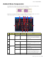
• Ambient Noise Compensator component added (page 379).
• Audio Detector component added (page 381).
• Auto Gain Control component added (page 382).
• Auto Mixer II component added (page 431).
• Simple Mixer component added (page 450).
• Room Combiner component added (page 460).
• Matrix Mixer and Router component variations added.
Main Panel Window
• To allow project information to be easily reproduced on a different computer, it is now possible to
export and import all necessary files at once, rather than only project files with the “.daf”
extension (page 45).
• A Device Information window that lists the status of all devices has been added (page 190).
• It is now possible to individually set each user control to determine whether it will open
automatically when the project file is opened (page 91).
• In accordance with the above change, the Startup User Control item has been removed from the
Security dialog box.
• It is now possible to assign Direct Parameter Value to the GPI input function, and assign Direct
Parameter Value and Audio Detector to the GPI output function (page 112, page 122).
• An option that automatically saves the project file (.daf extension) in the DME unit when going
online has been added (page 98).
• It is now possible to control internal DME-24N/DME8i-C/DME4io-C/DME8i-ES/DME4io-ES head
amps from a PM5D or other compatible mixing console (page 141).
• Remote control from AMX, Crestron, and similar controllers is now possible via Ethernet
connection only for DME Satellite units. (page 171).
• The display format of the parameter values displayed in the Remote Control Setup List and
Parameter List dialog box can now be switched between the internal settings and the values
displayed in the editor windows (page 139, page 147).
• The Event Logger window can now display additional error messages shown on the DME display
panel (page 80).
• It is now possible to set the DME unit so that the internally stored event log is not erased
(page 77).
• Improvements have been made to the additional error message information shown in the Event
Logger window.
• The DME unit internal clock and DME Designer time display now support daylight saving time
(DST) (page 180).
• Firmware updates can now be applied to entire device groups, for improved speed and
efficiency.

DME Designer Owner’s Manual
17
Designer Window
• It is now possible to set a “clear” background color for text, box, and ellipse objects (page 252,
page 254, page 256).
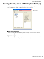
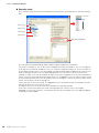
• Password entry is now required when opening a User Module Properties dialog box or saving/
exporting in a user module to which security has been applied.
• Linked software applications can now be launched from the Slot component contextual menu
(page 240).
• User module templates that use the same library are now categorized and displayed as user
module groups (page 310).
• Image files are now included in User Module exports.
• Component and parameter links can now be copied when DME objects, components, and user
modules are copied/pasted or duplicated.
• Parameter links are now saved when User Module data is saved/exported.
• When already-placed picture files are replaced, they will be updated and displayed correctly
without the need to restart the DME Designer application.
Component Editor Window
• [Line] and [Scene Recall] tools have been added to the User Module Editor and User Control
Editor design modes, allowing placement of lines and scene recall buttons (page 332).
• In the User Module Editor and User Control Editor it is now possible to convert placed sliders to
knobs, and vice-versa (page 343).
• More options are available for customizing the controls listed below in the User Module Editor
and User Control Editor:
- A property dialog box has been added for sliders, allowing customization of direction, scale,
color, size, and other parameters (page 345).
- Level meter size can be customized (page 347).
- A property dialog box has been added for slider level meters, allowing customization of
direction and size (page 348).
- Knob color and knob background color can be customized (page 344).
- Text background color can be customized (page 352).
- A property dialog box has been added for indicators, allowing customization of color and size
(page 348).
V3.0 Precautions
Use DME Designer V3.0 only with DME64N/24N V3.0 or later, DME Satellite V3.0 or later, and/or
SP2060 V1.2 or later. Refer to the Yamaha Pro Audio website (http://www.yamahaproaudio.com/)
details on combinations.
When combining DME64N/24N and DME Satellite units in a device group, be sure to assign a DME
Satellite unit as the device group master. Synchronization cannot be performed if a DME64N/24N is
assigned as the device group master.
When using the Windows Vista operating system, use only USB-MIDI Driver V3.0 or later, and DME-
N Network Driver V1.2 or later.

DME Designer Owner’s Manual
18
Changes from V3.0 to V3.5
Component
• Program Ducker component added (page 412).
• (V3.5.1) During installation it is possible to select and install speaker library data for third-part
speakers into the Speaker Processor component library.
Main Panel Window
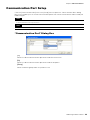
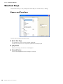
• MIDI Setup has been discontinued. Communication ports can now be directly selected via the
[Setup] menu [Communication Port] item. (page 155)
• (V3.5.1) [SP2060 Backup] has been added to the main panel window [Hardware] menu, allowing
internal SP2060 data to be transferred to a computer for backup. Multiple SP2060 units can be
restored from the backup data. (page 184)
Designer Window
• Improvements in the compiler algorithm achieve greater DSP resource utilization efficiency.
(page 98, page 305, page 308)
• MY16-ES64, MY16-EX, and MY16-MD64 I/O cards can now be specified for slot installation.
• The TX6n/TX5n/TX4n, ACD1, SB168-ES, IMX644, IPA8200, and NEXO products can now be
specified as external devices. V3.5.1 adds the IM8, MSR250, and other devices.
• When cascade connecting DME64N units across device groups, unit numbers are automatically
assigned when a connection is made between the [CAS IN] and [CAS OUT] terminals in the
Zone window.
Others (Firmware V3.09 changes)
• When controlling DME units remotely from a PM5D using the DME Control function, it is now
possible to set an ID number other than “2” for the group master DME unit. In this case the PM5D
firmware must be updated to V2.20 or later.
• It is now possible to replace the default DME64N/24N startup screen (normally the model name)
with an original graphic file. (page 71)
V3.5 Precautions
Use DME Designer version V3.5 with DME64N/24N or DME Satellite units running firmware version
between V3.0 and V3.8, and SP2060 units running firmware version V1.2 or later. Refer to the
Yamaha Pro Audio website (http://www.yamahaproaudio.com/) details on combinations.
When combining DME64N/24N and DME Satellite units in a device group, be sure to assign a DME
Satellite unit as the device group master. Synchronization cannot be performed if a DME64N/24N is
assigned as the device group master.
When using the Windows Vista operating system, use only USB-MIDI Driver V3.0 or later, and DME-
N Network Driver V1.2 or later.
When using the Windows 7 operating system, use only USB-MIDI Driver V3.0.4 or later, and DME-N
Network Driver V1.2.1 or later.

DME Designer Owner’s Manual
19
Changes from V3.5 to V3.8
New Features
• The DME64N/24N (V3.8x or later) can now be controlled via Ethernet connection from certain
external control devices.
• The DME64N/24N (V3.8x or later) can now be assigned as the device group master when the
device group is formed by combining the DME64N/24N (V3.8x or later) and the DME Satellite.
• A new [Show Unconnected Node] button which displays unconnected nodes has been added
into the Designer window toolbar.
• The window sizes of User Control Editor/User Module Editor can now be enlarged more than the
display resolution of computers. When a size is set that is larger than the display resolution of
computers in the “User Control Editor Settings” dialog box which can be selected in the context
menu, a scroll bar is displayed.
• New library data has been added into the Preset Library of the Speaker Processor.
• The following devices can now be set for the external devices: M7CL-48ES, DSR series, S5, NS-
AW series, NS-IC series, KMS-710, CD-S300RK, CD-C600RK, Gooseneck Microphone and
Boundary Microphone.
Changes
• The layout of the Remote functions and MIDI functions have been changed through revisions of
the operation of the Utility dialog.
Fixed Bugs
• Fixed problems in which the Remote Control settings were not applied to the DME Designer
appropriately when synchronizing.
• Fixed a problem in which the meter laid out in User Control might not move.
• Fixed a problem in which the window might not be displayed when the external display status
was changed.
• Fixed a problem in which the parameters of both Recall Safe and Global Link, might not be
displayed appropriately when Scene Recall was executed.
V3.8 Precautions
• Use DME Designer version V3.8.0 with DME64N/24N or DME Satellite units running firmware
version V3.0 or later, and SP2060 units running firmware version V1.2 or later.
• Use the latest DME Designer to update the DME firmware to the latest version.
• DME Designer cannot be used to update firmware version 3.5 or earlier to version 3.8 or later, or
to downgrade from version 3.8 or later to version 3.5 or earlier (this does not apply to the SP2060
or ICP1). Contact your Yamaha dealer.
• Save an up-to-date DME project file (*.daf). Don’t update unless an up-to-date “.daf” file has
already been saved on your computer. Without the “daf” file, you will not be able to restore DME
operation.
• When DME64N/24N units running firmware version 3.5 or earlier and DME64N/24N or DME
Satellite units running firmware versions 3.8 or later are combined in the same device group,
DME64N/24N units running firmware version 3.5 or earlier cannot be designated as the group
master.
• If the Program Ducker component is used, both DME firmware and DME Designer versions must
be V3.5 or later.

DME Designer Owner’s Manual
20
Changes from V3.8 to V4.0
New Features
• The MY4-AEC card can now be selected for I/O card slots. AEC components, which are available
when the card is installed, have been added.
• The “Partial Recall” function has been added. Scenes can now be recalled on a per component
basis. By utilizing both Recall Safe and the new Partial Recall functions, components to be
recalled or not recalled can now be selected precisely.
• Configurations can now be duplicated in the “Configuration Manager” window.
• In the Main Panel window, configuration names are now displayed, and configurations may be
selected.
• The VS4, VS6, and NS-IC600 can now be specified as external devices.
Changes
• The Remote V3.5 tab and the MIDI V3.5 tab in the “Utility” dialog box have been deleted.
• The [Cancel] button has been added in the “Project File has been modified. Save?” dialog box
which is displayed before closing DME Designer to cancel closing procedure.
Fixed Bugs
• Fixed a problem in which SP2060 configurations could be edited when the “Configuration
Manager” dialog box was opened via [Tools] menu [Configuration Manager] item.
• Fixed a problem in which configurations could be edited while online when the “Configuration
Manager” dialog box was opened via the context menu displayed by right clicking a DME object
in the Designer window.
• Fixed a problem in which the compiling procedure would occasionally complete successfully
even though an error should occur when an IN port was connected to multiple OUT ports.
• Fixed a problem in which the compiling procedure would occasionally not complete when
compiling was executed on a complex configuration with multiple SPX components.
• Fixed a problem in which the compiling procedure would occasionally not complete when
compiling was executed on a complex configuration having an SPX component with an output
connected to any other component.
• Fixed a problem in which the [+48V Master] indicator didn't light in the AD8HR component editor.
• Fixed a problem in which DME Designer could occasionally freeze when closing the application
by means other than clicking [Exit] in the [File] menu of the Main Panel window.
• Fixed a problem in which parameter links remained functional for parameters of different types
which should not be linked after the effect type was changed for an SPX component having
linked parameters.
• Fixed problems in which Scene Store and Recall functions might not work when Parameter Link
settings were no longer appropriate due to editing the Configuration.
V4.0 Precautions
• Use DME Designer V4.0 with DME64N/24N or DME Satellite units running firmware V4.0 or later,
and SP2060 units running firmware V1.2 or later.
• Use the latest DME Designer to update the DME firmware to the latest version.
• DME Designer V4.0 cannot be used to update firmware V3.5 or earlier to V4.0 or later, or to
downgrade from V4.0 or later to V3.5 or earlier (this does not apply to the SP2060 or ICP1).
Contact your Yamaha dealer.
• The DME firmware V3.8 can be updated to V4.0 using DME Designer V4.0.
Sayfa yükleniyor...
Sayfa yükleniyor...
Sayfa yükleniyor...
Sayfa yükleniyor...
Sayfa yükleniyor...
Sayfa yükleniyor...
Sayfa yükleniyor...
Sayfa yükleniyor...
Sayfa yükleniyor...
Sayfa yükleniyor...
Sayfa yükleniyor...
Sayfa yükleniyor...
Sayfa yükleniyor...
Sayfa yükleniyor...
Sayfa yükleniyor...
Sayfa yükleniyor...
Sayfa yükleniyor...
Sayfa yükleniyor...
Sayfa yükleniyor...
Sayfa yükleniyor...
Sayfa yükleniyor...
Sayfa yükleniyor...
Sayfa yükleniyor...
Sayfa yükleniyor...
Sayfa yükleniyor...
Sayfa yükleniyor...
Sayfa yükleniyor...
Sayfa yükleniyor...
Sayfa yükleniyor...
Sayfa yükleniyor...
Sayfa yükleniyor...
Sayfa yükleniyor...
Sayfa yükleniyor...
Sayfa yükleniyor...
Sayfa yükleniyor...
Sayfa yükleniyor...
Sayfa yükleniyor...
Sayfa yükleniyor...
Sayfa yükleniyor...
Sayfa yükleniyor...
Sayfa yükleniyor...
Sayfa yükleniyor...
Sayfa yükleniyor...
Sayfa yükleniyor...
Sayfa yükleniyor...
Sayfa yükleniyor...
Sayfa yükleniyor...
Sayfa yükleniyor...
Sayfa yükleniyor...
Sayfa yükleniyor...
Sayfa yükleniyor...
Sayfa yükleniyor...
Sayfa yükleniyor...
Sayfa yükleniyor...
Sayfa yükleniyor...
Sayfa yükleniyor...
Sayfa yükleniyor...
Sayfa yükleniyor...
Sayfa yükleniyor...
Sayfa yükleniyor...
Sayfa yükleniyor...
Sayfa yükleniyor...
Sayfa yükleniyor...
Sayfa yükleniyor...
Sayfa yükleniyor...
Sayfa yükleniyor...
Sayfa yükleniyor...
Sayfa yükleniyor...
Sayfa yükleniyor...
Sayfa yükleniyor...
Sayfa yükleniyor...
Sayfa yükleniyor...
Sayfa yükleniyor...
Sayfa yükleniyor...
Sayfa yükleniyor...
Sayfa yükleniyor...
Sayfa yükleniyor...
Sayfa yükleniyor...
Sayfa yükleniyor...
Sayfa yükleniyor...
Sayfa yükleniyor...
Sayfa yükleniyor...
Sayfa yükleniyor...
Sayfa yükleniyor...
Sayfa yükleniyor...
Sayfa yükleniyor...
Sayfa yükleniyor...
Sayfa yükleniyor...
Sayfa yükleniyor...
Sayfa yükleniyor...
Sayfa yükleniyor...
Sayfa yükleniyor...
Sayfa yükleniyor...
Sayfa yükleniyor...
Sayfa yükleniyor...
Sayfa yükleniyor...
Sayfa yükleniyor...
Sayfa yükleniyor...
Sayfa yükleniyor...
Sayfa yükleniyor...
Sayfa yükleniyor...
Sayfa yükleniyor...
Sayfa yükleniyor...
Sayfa yükleniyor...
Sayfa yükleniyor...
Sayfa yükleniyor...
Sayfa yükleniyor...
Sayfa yükleniyor...
Sayfa yükleniyor...
Sayfa yükleniyor...
Sayfa yükleniyor...
Sayfa yükleniyor...
Sayfa yükleniyor...
Sayfa yükleniyor...
Sayfa yükleniyor...
Sayfa yükleniyor...
Sayfa yükleniyor...
Sayfa yükleniyor...
Sayfa yükleniyor...
Sayfa yükleniyor...
Sayfa yükleniyor...
Sayfa yükleniyor...
Sayfa yükleniyor...
Sayfa yükleniyor...
Sayfa yükleniyor...
Sayfa yükleniyor...
Sayfa yükleniyor...
Sayfa yükleniyor...
Sayfa yükleniyor...
Sayfa yükleniyor...
Sayfa yükleniyor...
Sayfa yükleniyor...
Sayfa yükleniyor...
Sayfa yükleniyor...
Sayfa yükleniyor...
Sayfa yükleniyor...
Sayfa yükleniyor...
Sayfa yükleniyor...
Sayfa yükleniyor...
Sayfa yükleniyor...
Sayfa yükleniyor...
Sayfa yükleniyor...
Sayfa yükleniyor...
Sayfa yükleniyor...
Sayfa yükleniyor...
Sayfa yükleniyor...
Sayfa yükleniyor...
Sayfa yükleniyor...
Sayfa yükleniyor...
Sayfa yükleniyor...
Sayfa yükleniyor...
Sayfa yükleniyor...
Sayfa yükleniyor...
Sayfa yükleniyor...
Sayfa yükleniyor...
Sayfa yükleniyor...
Sayfa yükleniyor...
Sayfa yükleniyor...
Sayfa yükleniyor...
Sayfa yükleniyor...
Sayfa yükleniyor...
Sayfa yükleniyor...
Sayfa yükleniyor...
Sayfa yükleniyor...
Sayfa yükleniyor...
Sayfa yükleniyor...
Sayfa yükleniyor...
Sayfa yükleniyor...
Sayfa yükleniyor...
Sayfa yükleniyor...
Sayfa yükleniyor...
Sayfa yükleniyor...
Sayfa yükleniyor...
Sayfa yükleniyor...
Sayfa yükleniyor...
Sayfa yükleniyor...
Sayfa yükleniyor...
Sayfa yükleniyor...
Sayfa yükleniyor...
Sayfa yükleniyor...
Sayfa yükleniyor...
Sayfa yükleniyor...
Sayfa yükleniyor...
Sayfa yükleniyor...
Sayfa yükleniyor...
Sayfa yükleniyor...
Sayfa yükleniyor...
Sayfa yükleniyor...
Sayfa yükleniyor...
Sayfa yükleniyor...
Sayfa yükleniyor...
Sayfa yükleniyor...
Sayfa yükleniyor...
Sayfa yükleniyor...
Sayfa yükleniyor...
Sayfa yükleniyor...
Sayfa yükleniyor...
Sayfa yükleniyor...
Sayfa yükleniyor...
Sayfa yükleniyor...
Sayfa yükleniyor...
Sayfa yükleniyor...
Sayfa yükleniyor...
Sayfa yükleniyor...
Sayfa yükleniyor...
Sayfa yükleniyor...
Sayfa yükleniyor...
Sayfa yükleniyor...
Sayfa yükleniyor...
Sayfa yükleniyor...
Sayfa yükleniyor...
Sayfa yükleniyor...
Sayfa yükleniyor...
Sayfa yükleniyor...
Sayfa yükleniyor...
Sayfa yükleniyor...
Sayfa yükleniyor...
Sayfa yükleniyor...
Sayfa yükleniyor...
Sayfa yükleniyor...
Sayfa yükleniyor...
Sayfa yükleniyor...
Sayfa yükleniyor...
Sayfa yükleniyor...
Sayfa yükleniyor...
Sayfa yükleniyor...
Sayfa yükleniyor...
Sayfa yükleniyor...
Sayfa yükleniyor...
Sayfa yükleniyor...
Sayfa yükleniyor...
Sayfa yükleniyor...
Sayfa yükleniyor...
Sayfa yükleniyor...
Sayfa yükleniyor...
Sayfa yükleniyor...
Sayfa yükleniyor...
Sayfa yükleniyor...
Sayfa yükleniyor...
Sayfa yükleniyor...
Sayfa yükleniyor...
Sayfa yükleniyor...
Sayfa yükleniyor...
Sayfa yükleniyor...
Sayfa yükleniyor...
Sayfa yükleniyor...
Sayfa yükleniyor...
Sayfa yükleniyor...
Sayfa yükleniyor...
Sayfa yükleniyor...
Sayfa yükleniyor...
Sayfa yükleniyor...
Sayfa yükleniyor...
Sayfa yükleniyor...
Sayfa yükleniyor...
Sayfa yükleniyor...
Sayfa yükleniyor...
Sayfa yükleniyor...
Sayfa yükleniyor...
Sayfa yükleniyor...
Sayfa yükleniyor...
Sayfa yükleniyor...
Sayfa yükleniyor...
Sayfa yükleniyor...
Sayfa yükleniyor...
Sayfa yükleniyor...
Sayfa yükleniyor...
Sayfa yükleniyor...
Sayfa yükleniyor...
Sayfa yükleniyor...
Sayfa yükleniyor...
Sayfa yükleniyor...
Sayfa yükleniyor...
Sayfa yükleniyor...
Sayfa yükleniyor...
Sayfa yükleniyor...
Sayfa yükleniyor...
Sayfa yükleniyor...
Sayfa yükleniyor...
Sayfa yükleniyor...
Sayfa yükleniyor...
Sayfa yükleniyor...
Sayfa yükleniyor...
Sayfa yükleniyor...
Sayfa yükleniyor...
Sayfa yükleniyor...
Sayfa yükleniyor...
Sayfa yükleniyor...
Sayfa yükleniyor...
Sayfa yükleniyor...
Sayfa yükleniyor...
Sayfa yükleniyor...
Sayfa yükleniyor...
Sayfa yükleniyor...
Sayfa yükleniyor...
Sayfa yükleniyor...
Sayfa yükleniyor...
Sayfa yükleniyor...
Sayfa yükleniyor...
Sayfa yükleniyor...
Sayfa yükleniyor...
Sayfa yükleniyor...
Sayfa yükleniyor...
Sayfa yükleniyor...
Sayfa yükleniyor...
Sayfa yükleniyor...
Sayfa yükleniyor...
Sayfa yükleniyor...
Sayfa yükleniyor...
Sayfa yükleniyor...
Sayfa yükleniyor...
Sayfa yükleniyor...
Sayfa yükleniyor...
Sayfa yükleniyor...
Sayfa yükleniyor...
Sayfa yükleniyor...
Sayfa yükleniyor...
Sayfa yükleniyor...
Sayfa yükleniyor...
Sayfa yükleniyor...
Sayfa yükleniyor...
Sayfa yükleniyor...
Sayfa yükleniyor...
Sayfa yükleniyor...
Sayfa yükleniyor...
Sayfa yükleniyor...
Sayfa yükleniyor...
Sayfa yükleniyor...
Sayfa yükleniyor...
Sayfa yükleniyor...
Sayfa yükleniyor...
Sayfa yükleniyor...
Sayfa yükleniyor...
Sayfa yükleniyor...
Sayfa yükleniyor...
Sayfa yükleniyor...
Sayfa yükleniyor...
Sayfa yükleniyor...
Sayfa yükleniyor...
Sayfa yükleniyor...
Sayfa yükleniyor...
Sayfa yükleniyor...
Sayfa yükleniyor...
Sayfa yükleniyor...
Sayfa yükleniyor...
Sayfa yükleniyor...
Sayfa yükleniyor...
Sayfa yükleniyor...
Sayfa yükleniyor...
Sayfa yükleniyor...
Sayfa yükleniyor...
Sayfa yükleniyor...
Sayfa yükleniyor...
Sayfa yükleniyor...
Sayfa yükleniyor...
Sayfa yükleniyor...
Sayfa yükleniyor...
Sayfa yükleniyor...
Sayfa yükleniyor...
Sayfa yükleniyor...
Sayfa yükleniyor...
Sayfa yükleniyor...
Sayfa yükleniyor...
Sayfa yükleniyor...
Sayfa yükleniyor...
Sayfa yükleniyor...
Sayfa yükleniyor...
Sayfa yükleniyor...
Sayfa yükleniyor...
Sayfa yükleniyor...
Sayfa yükleniyor...
Sayfa yükleniyor...
Sayfa yükleniyor...
Sayfa yükleniyor...
Sayfa yükleniyor...
Sayfa yükleniyor...
Sayfa yükleniyor...
Sayfa yükleniyor...
Sayfa yükleniyor...
Sayfa yükleniyor...
Sayfa yükleniyor...
Sayfa yükleniyor...
Sayfa yükleniyor...
Sayfa yükleniyor...
Sayfa yükleniyor...
Sayfa yükleniyor...
Sayfa yükleniyor...
Sayfa yükleniyor...
Sayfa yükleniyor...
Sayfa yükleniyor...
Sayfa yükleniyor...
Sayfa yükleniyor...
Sayfa yükleniyor...
Sayfa yükleniyor...
Sayfa yükleniyor...
Sayfa yükleniyor...
Sayfa yükleniyor...
Sayfa yükleniyor...
Sayfa yükleniyor...
Sayfa yükleniyor...
Sayfa yükleniyor...
Sayfa yükleniyor...
Sayfa yükleniyor...
Sayfa yükleniyor...
Sayfa yükleniyor...
Sayfa yükleniyor...
Sayfa yükleniyor...
Sayfa yükleniyor...
Sayfa yükleniyor...
Sayfa yükleniyor...
Sayfa yükleniyor...
Sayfa yükleniyor...
Sayfa yükleniyor...
Sayfa yükleniyor...
Sayfa yükleniyor...
Sayfa yükleniyor...
Sayfa yükleniyor...
Sayfa yükleniyor...
Sayfa yükleniyor...
Sayfa yükleniyor...
Sayfa yükleniyor...
Sayfa yükleniyor...
Sayfa yükleniyor...
Sayfa yükleniyor...
Sayfa yükleniyor...
Sayfa yükleniyor...
Sayfa yükleniyor...
Sayfa yükleniyor...
Sayfa yükleniyor...
Sayfa yükleniyor...
Sayfa yükleniyor...
Sayfa yükleniyor...
Sayfa yükleniyor...
Sayfa yükleniyor...
Sayfa yükleniyor...
Sayfa yükleniyor...
Sayfa yükleniyor...
Sayfa yükleniyor...
Sayfa yükleniyor...
Sayfa yükleniyor...
Sayfa yükleniyor...
Sayfa yükleniyor...
Sayfa yükleniyor...
Sayfa yükleniyor...
Sayfa yükleniyor...
Sayfa yükleniyor...
Sayfa yükleniyor...
Sayfa yükleniyor...
Sayfa yükleniyor...
Sayfa yükleniyor...
Sayfa yükleniyor...
Sayfa yükleniyor...
Sayfa yükleniyor...
Sayfa yükleniyor...
Sayfa yükleniyor...
Sayfa yükleniyor...
Sayfa yükleniyor...
Sayfa yükleniyor...
Sayfa yükleniyor...
Sayfa yükleniyor...
Sayfa yükleniyor...
Sayfa yükleniyor...
Sayfa yükleniyor...
Sayfa yükleniyor...
Sayfa yükleniyor...
Sayfa yükleniyor...
Sayfa yükleniyor...
Sayfa yükleniyor...
Sayfa yükleniyor...
Sayfa yükleniyor...
Sayfa yükleniyor...
Sayfa yükleniyor...
Sayfa yükleniyor...
Sayfa yükleniyor...
Sayfa yükleniyor...
Sayfa yükleniyor...
Sayfa yükleniyor...
Sayfa yükleniyor...
Sayfa yükleniyor...
Sayfa yükleniyor...
Sayfa yükleniyor...
Sayfa yükleniyor...
Sayfa yükleniyor...
Sayfa yükleniyor...
Sayfa yükleniyor...
Sayfa yükleniyor...
Sayfa yükleniyor...
Sayfa yükleniyor...
Sayfa yükleniyor...
Sayfa yükleniyor...
Sayfa yükleniyor...
Sayfa yükleniyor...
Sayfa yükleniyor...
Sayfa yükleniyor...
Sayfa yükleniyor...
Sayfa yükleniyor...
Sayfa yükleniyor...
Sayfa yükleniyor...
Sayfa yükleniyor...
Sayfa yükleniyor...
Sayfa yükleniyor...
Sayfa yükleniyor...
Sayfa yükleniyor...
Sayfa yükleniyor...
Sayfa yükleniyor...
Sayfa yükleniyor...
-
 1
1
-
 2
2
-
 3
3
-
 4
4
-
 5
5
-
 6
6
-
 7
7
-
 8
8
-
 9
9
-
 10
10
-
 11
11
-
 12
12
-
 13
13
-
 14
14
-
 15
15
-
 16
16
-
 17
17
-
 18
18
-
 19
19
-
 20
20
-
 21
21
-
 22
22
-
 23
23
-
 24
24
-
 25
25
-
 26
26
-
 27
27
-
 28
28
-
 29
29
-
 30
30
-
 31
31
-
 32
32
-
 33
33
-
 34
34
-
 35
35
-
 36
36
-
 37
37
-
 38
38
-
 39
39
-
 40
40
-
 41
41
-
 42
42
-
 43
43
-
 44
44
-
 45
45
-
 46
46
-
 47
47
-
 48
48
-
 49
49
-
 50
50
-
 51
51
-
 52
52
-
 53
53
-
 54
54
-
 55
55
-
 56
56
-
 57
57
-
 58
58
-
 59
59
-
 60
60
-
 61
61
-
 62
62
-
 63
63
-
 64
64
-
 65
65
-
 66
66
-
 67
67
-
 68
68
-
 69
69
-
 70
70
-
 71
71
-
 72
72
-
 73
73
-
 74
74
-
 75
75
-
 76
76
-
 77
77
-
 78
78
-
 79
79
-
 80
80
-
 81
81
-
 82
82
-
 83
83
-
 84
84
-
 85
85
-
 86
86
-
 87
87
-
 88
88
-
 89
89
-
 90
90
-
 91
91
-
 92
92
-
 93
93
-
 94
94
-
 95
95
-
 96
96
-
 97
97
-
 98
98
-
 99
99
-
 100
100
-
 101
101
-
 102
102
-
 103
103
-
 104
104
-
 105
105
-
 106
106
-
 107
107
-
 108
108
-
 109
109
-
 110
110
-
 111
111
-
 112
112
-
 113
113
-
 114
114
-
 115
115
-
 116
116
-
 117
117
-
 118
118
-
 119
119
-
 120
120
-
 121
121
-
 122
122
-
 123
123
-
 124
124
-
 125
125
-
 126
126
-
 127
127
-
 128
128
-
 129
129
-
 130
130
-
 131
131
-
 132
132
-
 133
133
-
 134
134
-
 135
135
-
 136
136
-
 137
137
-
 138
138
-
 139
139
-
 140
140
-
 141
141
-
 142
142
-
 143
143
-
 144
144
-
 145
145
-
 146
146
-
 147
147
-
 148
148
-
 149
149
-
 150
150
-
 151
151
-
 152
152
-
 153
153
-
 154
154
-
 155
155
-
 156
156
-
 157
157
-
 158
158
-
 159
159
-
 160
160
-
 161
161
-
 162
162
-
 163
163
-
 164
164
-
 165
165
-
 166
166
-
 167
167
-
 168
168
-
 169
169
-
 170
170
-
 171
171
-
 172
172
-
 173
173
-
 174
174
-
 175
175
-
 176
176
-
 177
177
-
 178
178
-
 179
179
-
 180
180
-
 181
181
-
 182
182
-
 183
183
-
 184
184
-
 185
185
-
 186
186
-
 187
187
-
 188
188
-
 189
189
-
 190
190
-
 191
191
-
 192
192
-
 193
193
-
 194
194
-
 195
195
-
 196
196
-
 197
197
-
 198
198
-
 199
199
-
 200
200
-
 201
201
-
 202
202
-
 203
203
-
 204
204
-
 205
205
-
 206
206
-
 207
207
-
 208
208
-
 209
209
-
 210
210
-
 211
211
-
 212
212
-
 213
213
-
 214
214
-
 215
215
-
 216
216
-
 217
217
-
 218
218
-
 219
219
-
 220
220
-
 221
221
-
 222
222
-
 223
223
-
 224
224
-
 225
225
-
 226
226
-
 227
227
-
 228
228
-
 229
229
-
 230
230
-
 231
231
-
 232
232
-
 233
233
-
 234
234
-
 235
235
-
 236
236
-
 237
237
-
 238
238
-
 239
239
-
 240
240
-
 241
241
-
 242
242
-
 243
243
-
 244
244
-
 245
245
-
 246
246
-
 247
247
-
 248
248
-
 249
249
-
 250
250
-
 251
251
-
 252
252
-
 253
253
-
 254
254
-
 255
255
-
 256
256
-
 257
257
-
 258
258
-
 259
259
-
 260
260
-
 261
261
-
 262
262
-
 263
263
-
 264
264
-
 265
265
-
 266
266
-
 267
267
-
 268
268
-
 269
269
-
 270
270
-
 271
271
-
 272
272
-
 273
273
-
 274
274
-
 275
275
-
 276
276
-
 277
277
-
 278
278
-
 279
279
-
 280
280
-
 281
281
-
 282
282
-
 283
283
-
 284
284
-
 285
285
-
 286
286
-
 287
287
-
 288
288
-
 289
289
-
 290
290
-
 291
291
-
 292
292
-
 293
293
-
 294
294
-
 295
295
-
 296
296
-
 297
297
-
 298
298
-
 299
299
-
 300
300
-
 301
301
-
 302
302
-
 303
303
-
 304
304
-
 305
305
-
 306
306
-
 307
307
-
 308
308
-
 309
309
-
 310
310
-
 311
311
-
 312
312
-
 313
313
-
 314
314
-
 315
315
-
 316
316
-
 317
317
-
 318
318
-
 319
319
-
 320
320
-
 321
321
-
 322
322
-
 323
323
-
 324
324
-
 325
325
-
 326
326
-
 327
327
-
 328
328
-
 329
329
-
 330
330
-
 331
331
-
 332
332
-
 333
333
-
 334
334
-
 335
335
-
 336
336
-
 337
337
-
 338
338
-
 339
339
-
 340
340
-
 341
341
-
 342
342
-
 343
343
-
 344
344
-
 345
345
-
 346
346
-
 347
347
-
 348
348
-
 349
349
-
 350
350
-
 351
351
-
 352
352
-
 353
353
-
 354
354
-
 355
355
-
 356
356
-
 357
357
-
 358
358
-
 359
359
-
 360
360
-
 361
361
-
 362
362
-
 363
363
-
 364
364
-
 365
365
-
 366
366
-
 367
367
-
 368
368
-
 369
369
-
 370
370
-
 371
371
-
 372
372
-
 373
373
-
 374
374
-
 375
375
-
 376
376
-
 377
377
-
 378
378
-
 379
379
-
 380
380
-
 381
381
-
 382
382
-
 383
383
-
 384
384
-
 385
385
-
 386
386
-
 387
387
-
 388
388
-
 389
389
-
 390
390
-
 391
391
-
 392
392
-
 393
393
-
 394
394
-
 395
395
-
 396
396
-
 397
397
-
 398
398
-
 399
399
-
 400
400
-
 401
401
-
 402
402
-
 403
403
-
 404
404
-
 405
405
-
 406
406
-
 407
407
-
 408
408
-
 409
409
-
 410
410
-
 411
411
-
 412
412
-
 413
413
-
 414
414
-
 415
415
-
 416
416
-
 417
417
-
 418
418
-
 419
419
-
 420
420
-
 421
421
-
 422
422
-
 423
423
-
 424
424
-
 425
425
-
 426
426
-
 427
427
-
 428
428
-
 429
429
-
 430
430
-
 431
431
-
 432
432
-
 433
433
-
 434
434
-
 435
435
-
 436
436
-
 437
437
-
 438
438
-
 439
439
-
 440
440
-
 441
441
-
 442
442
-
 443
443
-
 444
444
-
 445
445
-
 446
446
-
 447
447
-
 448
448
-
 449
449
-
 450
450
-
 451
451
-
 452
452
-
 453
453
-
 454
454
-
 455
455
-
 456
456
-
 457
457
-
 458
458
-
 459
459
-
 460
460
-
 461
461
-
 462
462
-
 463
463
-
 464
464
-
 465
465
-
 466
466
-
 467
467
-
 468
468
-
 469
469
-
 470
470
-
 471
471
-
 472
472
-
 473
473
-
 474
474
-
 475
475
-
 476
476
-
 477
477
-
 478
478
-
 479
479
-
 480
480
-
 481
481
-
 482
482
-
 483
483
-
 484
484
-
 485
485
-
 486
486
-
 487
487
-
 488
488
-
 489
489
-
 490
490
-
 491
491
-
 492
492
-
 493
493
-
 494
494
-
 495
495
-
 496
496
-
 497
497
-
 498
498
-
 499
499
-
 500
500
-
 501
501
-
 502
502
-
 503
503
-
 504
504
-
 505
505
-
 506
506
-
 507
507
-
 508
508
-
 509
509
-
 510
510
-
 511
511
-
 512
512
-
 513
513
-
 514
514
-
 515
515
-
 516
516
-
 517
517
-
 518
518
-
 519
519
-
 520
520
-
 521
521
-
 522
522
-
 523
523
-
 524
524
-
 525
525
-
 526
526


Yamaha v4 El kitabı
- Kategori
- Yazılım
- Tip
- El kitabı
- Bu kılavuz aynı zamanda aşağıdakiler için de uygundur:
diğer dillerde
- español: Yamaha v4 El manual del propietario
- français: Yamaha v4 Le manuel du propriétaire
- italiano: Yamaha v4 Manuale del proprietario
- svenska: Yamaha v4 Bruksanvisning
- čeština: Yamaha v4 Návod k obsluze
- polski: Yamaha v4 Instrukcja obsługi
- Deutsch: Yamaha v4 Bedienungsanleitung
- português: Yamaha v4 Manual do proprietário
- English: Yamaha v4 Owner's manual
- dansk: Yamaha v4 Brugervejledning
- русский: Yamaha v4 Инструкция по применению
- suomi: Yamaha v4 Omistajan opas
- Nederlands: Yamaha v4 de handleiding
- română: Yamaha v4 Manualul proprietarului
İlgili makaleler
Diğer belgeler
-
Mitsubishi Heavy Industries eco touch RC-EX1A Yükleme Rehberi
-
Sharp MX-C310 Kullanma talimatları
-
HEIDENHAIN ND 1300 - V2.1.0 GUIDE El kitabı
-
Acard AEC-6293M Kullanım kılavuzu
-
CAME MOTOSTAR Kullanım kılavuzu
-
Danfoss SonicHeat Energy Meters Kullanici rehberi
-
Gossen MetraWatt METRAHit ASi V3.0 Kullanma talimatları