
ITALY
MADE IN
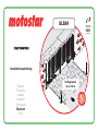
SLS24
W
A
R
R
A
N
T
Y
•
G
A
R
A
N
T
I
E
•
G
A
R
A
N
Z
I
A
•
G
A
R
A
N
T
I
A
•
G
A
R
A
N
T
I
E
•
G
A
R
A
N
T
I
E
•
Y
E
A
R
S
•
A
N
S
•
A
N
N
I
•
A
Ñ
O
S
•
A
N
O
•
J
A
H
R
E
•
3
Installation
manual
OPERATOR
OPERATOR
FOR
FOR
SWING GATES
SWING GATES
width of gate leaf
2.2 m max
English
Français
Italiano
Español
Português
Deutsch
Türk

2
-
FG00703M07
-
1
- 06/2017
ENGLISH
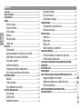
Summary
GENERAL WARNINGS ...................................................................3
KEY ..............................................................................................5
DESCRIPTION ...............................................................................5
Intended use ...........................................................5
Limits to use ...........................................................5
Technical data ..........................................................6
Dimensions ..............................................................6
Description of parts .................................................7
Standard installation ................................................8
INSTALLING ..................................................................................9
Preliminary checks ...................................................9
Checking measurements and applicative dimensions ...10
Cable type and minimum thicknesses ........................11
Preliminary works ...................................................12
Fastening the braces ...............................................13
Fastening the operator ............................................15
Establishing the limit-switch points ...........................18
CONTROL PANEL .........................................................................20
Dimensions ............................................................ 20
Main components .................................................. 21
Fastening and mounting the box .............................. 22
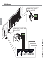
ELECTRICAL CONNECTIONS .........................................................23
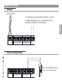
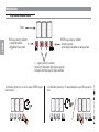
Power supply ......................................................... 23
Electric lock ........................................................... 23
Gearmotors ........................................................... 24
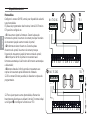
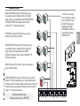
Command and control devices ................................. 25
Safety devices ....................................................... 26
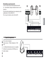
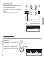
Signaling devices .................................................... 27
PROGRAMMING .........................................................................28
Description of programming commands .................... 28
Functions menu ..................................................... 29
SETTING UP ................................................................................34
Motor type ........................................................... 34
Number of motors ................................................. 34
Motors test .......................................................... 35
Self-learning of the gate-leaf travel .......................... 36
MANAGING USERS .....................................................................38
Adding users with an associated command ............... 38
Deleting a single user ............................................. 39
ILLUSTRATION OF THE SLOW-DOWN AND APPROACH AREAS AND
POINTS ......................................................................................40
ERROR MESSAGE ........................................................................41
FINAL OPERATIONS.....................................................................41
INWARD OPENING CONNECTIONS AND INSTALLING ....................42
Measurements and applicative dimensions ............... 42
Fastening braces and gearmotors............................ 43
Electrical connections ............................................. 43
DISMANTLING AND DISPOSAL ....................................................44
DECLARATION OF CONFORMITY ...................................................44

3
-
FG00703M07
-
1
- 06/2017
ENGLISH
This product must only be used for its specifi cally intended
purpose. Any other use is dangerous. LABEL HABITAT SAS
is not liable for any damage caused by improper, wrongful
or unreasonable use of this product. • This manual's
product is defi ned by machinery directive 2006/42/CE as
"partly-completed machinery". Quasi-completed machinery
is a set that almost constitutes a machine, but which,
alone, cannot ensure a clearly defi ned application. Partly-
completed machinery is only destined to be incorporated or
assembled to other machinery or other partly-completed
machinery or apparatuses to build machinery that is
regulated by Directive 2006/42/CE. The fi nal installation
must be compliant with European directive 2006/42/CE and
European reference standards:
EN 13241-1, EN 12453, EN 12445 and EN 12635.
Given these considerations, all procedures stated in
this manual must be exclusively performed by expert,
qualifi ed staff.• The operator cannot be used with gates
fi tted with pedestrian doors, unless its operation can
be activated only when the pedestrian door is in safety
position • Make sure that people are not entrapped
between the gate's moving and fi xed parts due to the
gate's movement • Before installing the operator, check
that the gate is in proper mechanical conditions, that it
is properly balanced and that it properly closes: if any of
these conditions are not met, do not continue before having
met all safety requirements • Make sure that opening and
closing limiters are fi tted • Make sure the operator is
installed onto a sturdy surface that is protected from any
impacting shocks • Make sure that mechanical stops are
already installed • If the operator is installed lower than
2.5 from the ground or from any other access level, fi t any
protections and signs to prevent hazardous situations •
Do not fi t the operator upside down or onto elements that
could yield to its weight If necessary, add reinforcements
to the fastening points • Do not install door or gate leaves
on tilted surfaces • Check that no lawn watering devices
spray the operator with water from the bottom up •
Suitably section off and demarcate the entire installation
site to prevent unauthorized persons from entering the
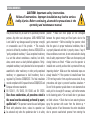
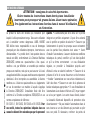
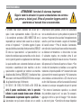
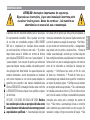
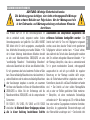
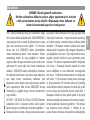
CAUTION: Important safety instructions.
Follow all instructions. Improper installation may lead to serious
bodily injuries. Before continuing, alsoread the precautions in the
operating and maintenance manual.
GENERAL WARNINGS

4
-
FG00703M07
-
1
- 06/2017
ENGLISH
area, especially minors and children • Fit cautionary signs,
such as the gate plate, wherever needed and in plain sight
• Use proper protections to prevent mechanical hazards
when people are loitering around the machinery's range
of action, for example avoid crushing of fi ngers between
the drive shaft and the mechanical stops, avoid crushing
when the gate is opening • The electrical cables must run
through the cable glands and not touch any parts that may
overheat, such as the motor, transformer, and so on • All
command and control devices must be installed at least
1.85 m from the perimeter of the gate's range of action
or where they cannot be reached through the gate from
the outside • All switches in maintained action mode must
be positioned so that the moving gates leaves, the transit
areas and vehicle thru-ways are completely visible, and yet
the switches must be also away from any moving parts •
Unless a key switch is used, all control devices must be
fi tted at a height of at least 1.5 mand wherethey are not
accessible to the public • Before handing over to users,
check that the system is compliant with the 2006/42/
CEuniformed Machinery DirectiveMake sure that the
operator has been properly adjusted and that the safety
and protection devices, and the manual release, are working
properly • Affi x a permanent tag, that describes how to
use the manual release mechanism, close to the mechanism
• Make sure to hand over to the end user, all operating
manuals for the products that make up the fi nal machinery
• Set up a suitable dual pole cut off device along the power
supply that is compliant with the installation rules. It should
completely cut off the power supply according to category III
surcharge conditions • The gearmotor must be exclusively
powered by very low safety voltage, which corresponds to
what is stated in the markings on the motor itself, and by
using the control panel supplied in the KIT.

5
-
FG00703M07
-
1
- 06/2017
0
50
100
150
200
250
300
350
0
1
1,25 1,5 1,75 2 2,25
2,2
215
ENGLISH
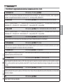
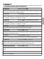
KEY
This symbol shows which parts to read carefully.
This symbol shows which parts describe safety issues
This symbol shows which parts to tell users about.
THE MEASUREMENTS, UNLESS OTHERWISE STATED, ARE IN MILLIMETERS. THE CONTENTS OF THIS MANUAL MAY CHANGE, AT ANY TIME, AND WITHOUT NOTICE.
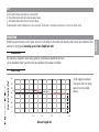
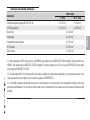
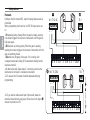
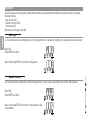
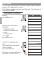
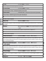
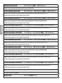
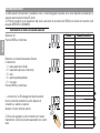
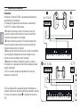
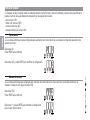
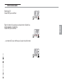
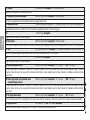
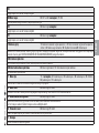
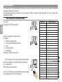
DESCRIPTION
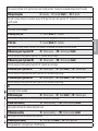
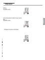
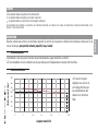
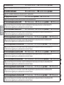
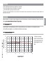
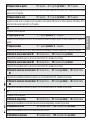
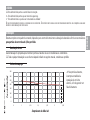
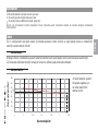
Complete system featuring control panel, device for controlling the movement and detecting obstructions plus mechanical limit-
switches for swing gates measuring up to 2.2 m in length (per leaf).
Intended use
This operator is designed to power swing gates for residential and apartment block use.
Any installation and/or use other than that specifi ed in this manual is forbidden.
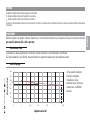
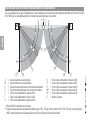
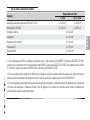
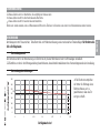
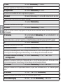
Gate-leaf weight (Kg)
Gate-leaf length (m)
We suggest you always
fi t an electrolock onto swing
gates for a more reliable
closure.
Limits to use

6
-
FG00703M07
-
1
- 06/2017
#
#
#
#
IP54
IP44
ENGLISH
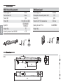
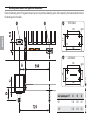
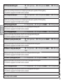
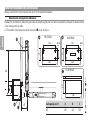
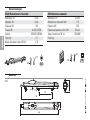
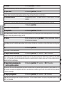
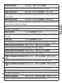
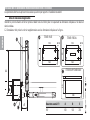
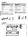
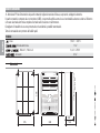
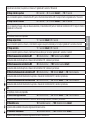
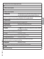
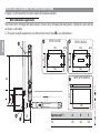
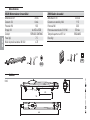
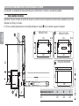
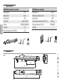
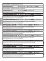
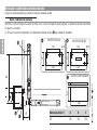
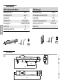
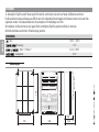
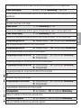
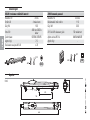
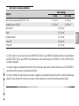
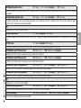
Dimensions
(mm)
Technical data
SLS24 (Irreversible gearmotor) ZL92 (Control panel)
Power supply (V) 24 DC Power supply (V) 230 AC
Current draw (A) 4 max. Consumption in stand-by mode (mA) 110
Power (W) 100 Power (W) 300
Thrust (N) from 400 to 2,000 Power of 24 V (W) accessories 50 max
Cycles/hr CONTINUOUS
SERVICES Opening time at 90° (s) ADJUSTABLE
Weight (Kg) 7.5 Weight (Kg) -
Acoustic pressure level (dB (A)) ≤70

7
-
FG00703M07
-
1
- 06/2017
}
x 2
}
x 1
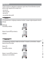
ENGLISH
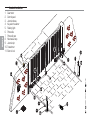
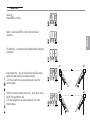
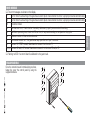
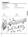
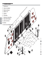
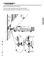
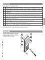
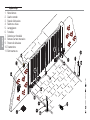
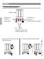
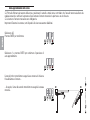
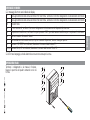
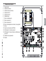
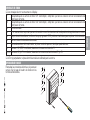
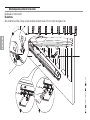
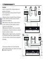
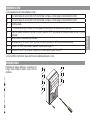
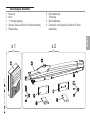
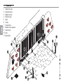
Description of parts
1. Control panel
2. Gearmotor
Release hatch
4. Bolt, nut and bushing for tail brace
5. Post bracket
6. Tail brace
7. Gate bracket
8. Head brace
9. Distancer, washer and nut for head brace

8
-
FG00703M07
-
1
- 06/2017
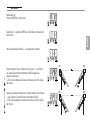
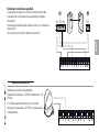
ENGLISH
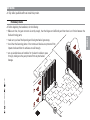
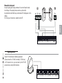
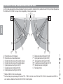
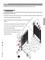
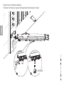
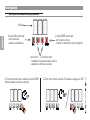
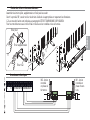
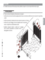
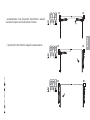
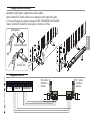
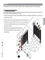
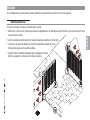
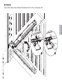
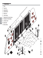
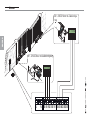
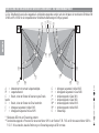
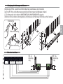
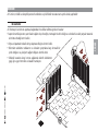
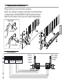
Standard installation
1. Gearmotor
2. Control panel
3. Junction boxes
4. Key-switch selector
5. Flashing light
6. Photocells
7. Photocell post
8. Mechanical stop
9. Junction pit
10. Transmitter
11. Electric lock

9
-
FG00703M07
-
1
- 06/2017
ENGLISH
Preliminary checks
Before beginning the installation, do the following:
• Make sure that, the gate structure is sturdy enough, that the hinges work effi ciently and that there is no friction between the
fi xed and moving parts;
• make sure you have fi tted opening and closing mechanical gate stops;
• check that the fastening points of the motors and devices are protected from
impact shocks and that the surfaces are solid enough.
• set up suitable tubes and conduits for the electric cables to pass
through, making sure they are protected from any mechanical
damage.
INSTALLING
Only skilled, qualifi ed staff must install this product.

10
-
FG00703M07
-
1
- 06/2017
60
140
40
110 Ø 10
60
140
40
110 Ø 10
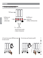
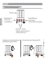
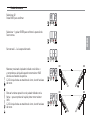
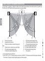
ENGLISH
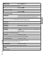
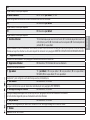
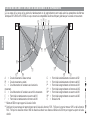
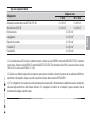
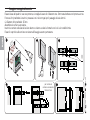
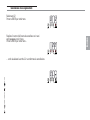
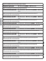
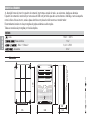
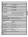
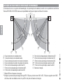
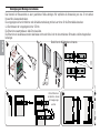
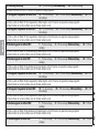
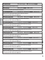
Checking measurements and applicative dimensions
Check the fastening point of the gate brace and set up the post brace fastening point, while respecting the measurements shown in
the drawing and in the table.
Leaf opening arc (°) A B C
90° 130 130 60
120° 130 110 50
POST BRACE
GATE BRACE

11
-
FG00703M07
-
1
- 06/2017
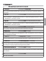
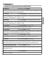
ENGLISH
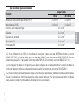
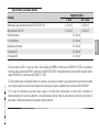
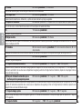
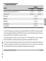
Cable type and minimum thicknesses
Connection cable length
< 20 m 20 < 30 m
Control board power supply 230 V AC (1P+N) 2 x 1.5 mm22 x 2.5 mm2
24 V DC gearmotor 3 x 1.5 mm23 x 2.5 mm2
Electric lock 2 x 0.5 mm2
Flashing light 2 x 0.5 mm2
Command and control devices 2 x 0.5 mm2
TX Photocells 2 x 0.5 mm2
RX photocells 4 x 0.5 mm2
When operating at 230 V and outdoors, use H05RN-F-type cables that are 60245 IEC 57 (IEC) compliant; whereas indoors, use
H05VV-F-type cables that are 60227 IEC 53 (IEC) compliant. For power supplies up to 48 V, you can use FROR 20-22 II-type cables
that comply with EN 50267-2-1 (CEI).
If cable lengths differ from those specified in the table, establish the cable sections depending on the actual power draw of the
connected devices and according to the provisions of regulation CEI EN 60204-1.
For multiple, sequential loads along the same line, the dimensions on the table need to be recalculated according to the actual
power draw and distances. For connecting products that are not contemplated in this manual, see the literature accompanying said
products

12
-
FG00703M07
-
1
- 06/2017
ENGLISH
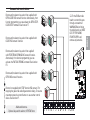
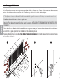
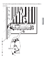
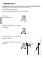
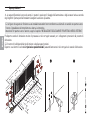
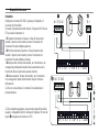
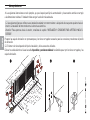
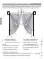
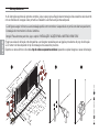
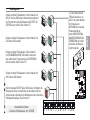
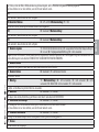
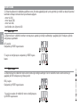
Preliminary works
The following illustrations are mere examples in that the space for fastening the operator and accessories varies depending on
the installation area. It is up to the fi tter, therefore, to choose the most suitable solution.
The fi gures below refer to a standard installation with gearmotor fi tted on the left and gate opening inward. Installing the
gearmotor on the right is symmetrical.
Warning! For outward opening gate leaves, follow the chapter titled "INSTALLING AND CONNECTING FOR OUTWARD OPENING".
Set up junction boxes fi tted with cable glands and corrugated conduits for the connections coming form the junction pit.
The number of tubes depends on the type of system and the accessories you are going to fi t.
Lay the electrical cables (see the table on types of cables and minimum thicknesses) by running them through the corrugated
conduits and junction boxes.

13
-
FG00703M07
-
1
- 06/2017
54
720
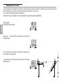
ENGLISH
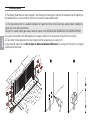
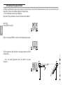
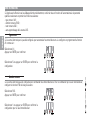
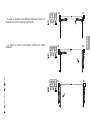
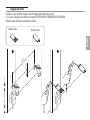
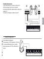
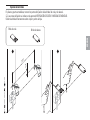
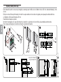
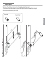
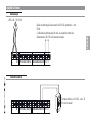
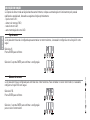
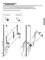
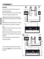
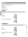
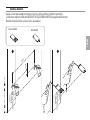
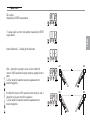
Fastening the braces
On metal posts and leaves, mark the fastening points for the tail and head braces.
The fastening measurements are listed in the paragraph titled CHECKING MEASUREMENTS AND APPLICATIVE DIMENSIONS.
Weld the braces directly onto the post and the gate leaf.
Head brace
Tail brace

14
-
FG00703M07
-
1
- 06/2017
110
40
54
110
4
0
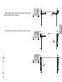
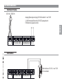
ENGLISH
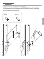
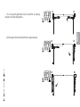
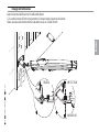
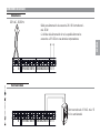
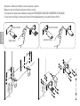
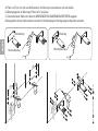
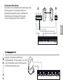
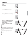
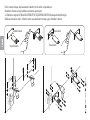
On non metal posts and leaves, assemble and weld the braces.
Mark the brace fastening points (post and gate).
The fastening measurements are listed in the paragraph titled CHECKING MEASUREMENTS AND APPLICATIVE DIMENSIONS.
Drill the anchoring points, fit the dowels or use plugs that will hold fast the screws.
Gate bracket
Head brace
Post bracket
Tail brace

15
-
FG00703M07
-
1
- 06/2017
UNI 5737 8x35
UNI 5588 M8
ENGLISH
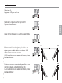
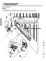
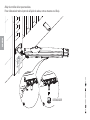
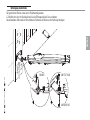
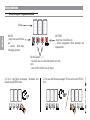
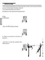
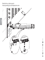
Fastening the operator
Fit the bushing (lubricated) into the post brace hole.
The brace is pre-drilled to vary the gate-opening angle.
Fasten the gearmotor's jointed-tail to the brace by using the supplied bolt and nut.
BUSHING

16
-
FG00703M07
-
1
- 06/2017
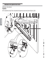
ENGLISH
Loosen the screws on the mechanical stops.
Fit the distances on the head attaching pin as shown in the drawing.
DISTANCER

17
-
FG00703M07
-
1
- 06/2017
UNI 7474 M12
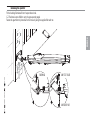
ENGLISH
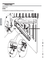
Open the leaf, fit the gearmotor attaching pin in to the eyelet hole on the head brace and fasten it by using the supplied washer and nut.
WASHER Ø26

18
-
FG00703M07
-
1
- 06/2017
ENGLISH
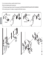
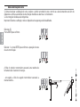
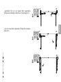
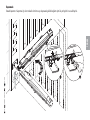
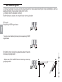
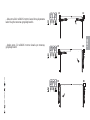
Establishing the limit-switch points
Release the gearmotor.
When opening.
Entirely open the gate leaf. Place the opening-thrust mechanical stop with the attachment pin and fasten it.

19
-
FG00703M07
-
1
- 06/2017
ENGLISH
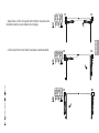
When closing.
Close the leaf. Place the closing-thrust mechanical stop with the attachment pin and fasten it.

20
-
FG00703M07
-
1
- 06/2017
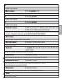
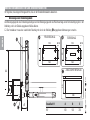
295
320
215 240 145
120
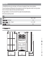
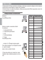
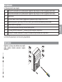
ENGLISH
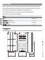
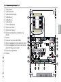
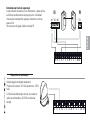
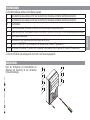
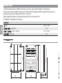
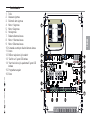
CONTROL PANEL
Warning! Before working on the control panel, cut off the main current supply and, if present, remove any batteries.
The control panel features an ABS casing with a fully opening hatch door which can fit hinges either to the left or to the right. Inside is
fitted the control board complete with radio receiver board and transformer.
We suggest installing it in an area that is protected from any impact shocks and possible tampering.
All connections are quick-fuse protected.
FUSES
- Line 1.6 A-F = 230 V
- Control board 1 A-F
- Motor 1 / Motor 2 6.3 A = 250 V
- Accessories 2 A-F
Dimensions
Sayfa yükleniyor...
Sayfa yükleniyor...
Sayfa yükleniyor...
Sayfa yükleniyor...
Sayfa yükleniyor...
Sayfa yükleniyor...
Sayfa yükleniyor...
Sayfa yükleniyor...
Sayfa yükleniyor...
Sayfa yükleniyor...
Sayfa yükleniyor...
Sayfa yükleniyor...
Sayfa yükleniyor...
Sayfa yükleniyor...
Sayfa yükleniyor...
Sayfa yükleniyor...
Sayfa yükleniyor...
Sayfa yükleniyor...
Sayfa yükleniyor...
Sayfa yükleniyor...
Sayfa yükleniyor...
Sayfa yükleniyor...
Sayfa yükleniyor...
Sayfa yükleniyor...
Sayfa yükleniyor...
Sayfa yükleniyor...
Sayfa yükleniyor...
Sayfa yükleniyor...
Sayfa yükleniyor...
Sayfa yükleniyor...
Sayfa yükleniyor...
Sayfa yükleniyor...
Sayfa yükleniyor...
Sayfa yükleniyor...
Sayfa yükleniyor...
Sayfa yükleniyor...
Sayfa yükleniyor...
Sayfa yükleniyor...
Sayfa yükleniyor...
Sayfa yükleniyor...
Sayfa yükleniyor...
Sayfa yükleniyor...
Sayfa yükleniyor...
Sayfa yükleniyor...
Sayfa yükleniyor...
Sayfa yükleniyor...
Sayfa yükleniyor...
Sayfa yükleniyor...
Sayfa yükleniyor...
Sayfa yükleniyor...
Sayfa yükleniyor...
Sayfa yükleniyor...
Sayfa yükleniyor...
Sayfa yükleniyor...
Sayfa yükleniyor...
Sayfa yükleniyor...
Sayfa yükleniyor...
Sayfa yükleniyor...
Sayfa yükleniyor...
Sayfa yükleniyor...
Sayfa yükleniyor...
Sayfa yükleniyor...
Sayfa yükleniyor...
Sayfa yükleniyor...
Sayfa yükleniyor...
Sayfa yükleniyor...
Sayfa yükleniyor...
Sayfa yükleniyor...
Sayfa yükleniyor...
Sayfa yükleniyor...
Sayfa yükleniyor...
Sayfa yükleniyor...
Sayfa yükleniyor...
Sayfa yükleniyor...
Sayfa yükleniyor...
Sayfa yükleniyor...
Sayfa yükleniyor...
Sayfa yükleniyor...
Sayfa yükleniyor...
Sayfa yükleniyor...
Sayfa yükleniyor...
Sayfa yükleniyor...
Sayfa yükleniyor...
Sayfa yükleniyor...
Sayfa yükleniyor...
Sayfa yükleniyor...
Sayfa yükleniyor...
Sayfa yükleniyor...
Sayfa yükleniyor...
Sayfa yükleniyor...
Sayfa yükleniyor...
Sayfa yükleniyor...
Sayfa yükleniyor...
Sayfa yükleniyor...
Sayfa yükleniyor...
Sayfa yükleniyor...
Sayfa yükleniyor...
Sayfa yükleniyor...
Sayfa yükleniyor...
Sayfa yükleniyor...
Sayfa yükleniyor...
Sayfa yükleniyor...
Sayfa yükleniyor...
Sayfa yükleniyor...
Sayfa yükleniyor...
Sayfa yükleniyor...
Sayfa yükleniyor...
Sayfa yükleniyor...
Sayfa yükleniyor...
Sayfa yükleniyor...
Sayfa yükleniyor...
Sayfa yükleniyor...
Sayfa yükleniyor...
Sayfa yükleniyor...
Sayfa yükleniyor...
Sayfa yükleniyor...
Sayfa yükleniyor...
Sayfa yükleniyor...
Sayfa yükleniyor...
Sayfa yükleniyor...
Sayfa yükleniyor...
Sayfa yükleniyor...
Sayfa yükleniyor...
Sayfa yükleniyor...
Sayfa yükleniyor...
Sayfa yükleniyor...
Sayfa yükleniyor...
Sayfa yükleniyor...
Sayfa yükleniyor...
Sayfa yükleniyor...
Sayfa yükleniyor...
Sayfa yükleniyor...
Sayfa yükleniyor...
Sayfa yükleniyor...
Sayfa yükleniyor...
Sayfa yükleniyor...
Sayfa yükleniyor...
Sayfa yükleniyor...
Sayfa yükleniyor...
Sayfa yükleniyor...
Sayfa yükleniyor...
Sayfa yükleniyor...
Sayfa yükleniyor...
Sayfa yükleniyor...
Sayfa yükleniyor...
Sayfa yükleniyor...
Sayfa yükleniyor...
Sayfa yükleniyor...
Sayfa yükleniyor...
Sayfa yükleniyor...
Sayfa yükleniyor...
Sayfa yükleniyor...
Sayfa yükleniyor...
Sayfa yükleniyor...
Sayfa yükleniyor...
Sayfa yükleniyor...
Sayfa yükleniyor...
Sayfa yükleniyor...
Sayfa yükleniyor...
Sayfa yükleniyor...
Sayfa yükleniyor...
Sayfa yükleniyor...
Sayfa yükleniyor...
Sayfa yükleniyor...
Sayfa yükleniyor...
Sayfa yükleniyor...
Sayfa yükleniyor...
Sayfa yükleniyor...
Sayfa yükleniyor...
Sayfa yükleniyor...
Sayfa yükleniyor...
Sayfa yükleniyor...
Sayfa yükleniyor...
Sayfa yükleniyor...
Sayfa yükleniyor...
Sayfa yükleniyor...
Sayfa yükleniyor...
Sayfa yükleniyor...
Sayfa yükleniyor...
Sayfa yükleniyor...
Sayfa yükleniyor...
Sayfa yükleniyor...
Sayfa yükleniyor...
Sayfa yükleniyor...
Sayfa yükleniyor...
Sayfa yükleniyor...
Sayfa yükleniyor...
Sayfa yükleniyor...
Sayfa yükleniyor...
Sayfa yükleniyor...
Sayfa yükleniyor...
Sayfa yükleniyor...
Sayfa yükleniyor...
Sayfa yükleniyor...
Sayfa yükleniyor...
Sayfa yükleniyor...
Sayfa yükleniyor...
Sayfa yükleniyor...
Sayfa yükleniyor...
Sayfa yükleniyor...
Sayfa yükleniyor...
Sayfa yükleniyor...
Sayfa yükleniyor...
Sayfa yükleniyor...
Sayfa yükleniyor...
Sayfa yükleniyor...
Sayfa yükleniyor...
Sayfa yükleniyor...
Sayfa yükleniyor...
Sayfa yükleniyor...
Sayfa yükleniyor...
Sayfa yükleniyor...
Sayfa yükleniyor...
Sayfa yükleniyor...
Sayfa yükleniyor...
Sayfa yükleniyor...
Sayfa yükleniyor...
Sayfa yükleniyor...
Sayfa yükleniyor...
Sayfa yükleniyor...
Sayfa yükleniyor...
Sayfa yükleniyor...
Sayfa yükleniyor...
Sayfa yükleniyor...
Sayfa yükleniyor...
Sayfa yükleniyor...
Sayfa yükleniyor...
Sayfa yükleniyor...
Sayfa yükleniyor...
Sayfa yükleniyor...
Sayfa yükleniyor...
Sayfa yükleniyor...
Sayfa yükleniyor...
Sayfa yükleniyor...
Sayfa yükleniyor...
Sayfa yükleniyor...
Sayfa yükleniyor...
Sayfa yükleniyor...
Sayfa yükleniyor...
Sayfa yükleniyor...
Sayfa yükleniyor...
Sayfa yükleniyor...
Sayfa yükleniyor...
Sayfa yükleniyor...
Sayfa yükleniyor...
Sayfa yükleniyor...
Sayfa yükleniyor...
Sayfa yükleniyor...
Sayfa yükleniyor...
Sayfa yükleniyor...
Sayfa yükleniyor...
Sayfa yükleniyor...
Sayfa yükleniyor...
Sayfa yükleniyor...
Sayfa yükleniyor...
Sayfa yükleniyor...
Sayfa yükleniyor...
Sayfa yükleniyor...
Sayfa yükleniyor...
Sayfa yükleniyor...
Sayfa yükleniyor...
Sayfa yükleniyor...
Sayfa yükleniyor...
Sayfa yükleniyor...
Sayfa yükleniyor...
Sayfa yükleniyor...
Sayfa yükleniyor...
Sayfa yükleniyor...
Sayfa yükleniyor...
Sayfa yükleniyor...
Sayfa yükleniyor...
Sayfa yükleniyor...
Sayfa yükleniyor...
Sayfa yükleniyor...
Sayfa yükleniyor...
Sayfa yükleniyor...
Sayfa yükleniyor...
Sayfa yükleniyor...
Sayfa yükleniyor...
Sayfa yükleniyor...
Sayfa yükleniyor...
Sayfa yükleniyor...
Sayfa yükleniyor...
Sayfa yükleniyor...
Sayfa yükleniyor...
Sayfa yükleniyor...
Sayfa yükleniyor...
Sayfa yükleniyor...
-
 1
1
-
 2
2
-
 3
3
-
 4
4
-
 5
5
-
 6
6
-
 7
7
-
 8
8
-
 9
9
-
 10
10
-
 11
11
-
 12
12
-
 13
13
-
 14
14
-
 15
15
-
 16
16
-
 17
17
-
 18
18
-
 19
19
-
 20
20
-
 21
21
-
 22
22
-
 23
23
-
 24
24
-
 25
25
-
 26
26
-
 27
27
-
 28
28
-
 29
29
-
 30
30
-
 31
31
-
 32
32
-
 33
33
-
 34
34
-
 35
35
-
 36
36
-
 37
37
-
 38
38
-
 39
39
-
 40
40
-
 41
41
-
 42
42
-
 43
43
-
 44
44
-
 45
45
-
 46
46
-
 47
47
-
 48
48
-
 49
49
-
 50
50
-
 51
51
-
 52
52
-
 53
53
-
 54
54
-
 55
55
-
 56
56
-
 57
57
-
 58
58
-
 59
59
-
 60
60
-
 61
61
-
 62
62
-
 63
63
-
 64
64
-
 65
65
-
 66
66
-
 67
67
-
 68
68
-
 69
69
-
 70
70
-
 71
71
-
 72
72
-
 73
73
-
 74
74
-
 75
75
-
 76
76
-
 77
77
-
 78
78
-
 79
79
-
 80
80
-
 81
81
-
 82
82
-
 83
83
-
 84
84
-
 85
85
-
 86
86
-
 87
87
-
 88
88
-
 89
89
-
 90
90
-
 91
91
-
 92
92
-
 93
93
-
 94
94
-
 95
95
-
 96
96
-
 97
97
-
 98
98
-
 99
99
-
 100
100
-
 101
101
-
 102
102
-
 103
103
-
 104
104
-
 105
105
-
 106
106
-
 107
107
-
 108
108
-
 109
109
-
 110
110
-
 111
111
-
 112
112
-
 113
113
-
 114
114
-
 115
115
-
 116
116
-
 117
117
-
 118
118
-
 119
119
-
 120
120
-
 121
121
-
 122
122
-
 123
123
-
 124
124
-
 125
125
-
 126
126
-
 127
127
-
 128
128
-
 129
129
-
 130
130
-
 131
131
-
 132
132
-
 133
133
-
 134
134
-
 135
135
-
 136
136
-
 137
137
-
 138
138
-
 139
139
-
 140
140
-
 141
141
-
 142
142
-
 143
143
-
 144
144
-
 145
145
-
 146
146
-
 147
147
-
 148
148
-
 149
149
-
 150
150
-
 151
151
-
 152
152
-
 153
153
-
 154
154
-
 155
155
-
 156
156
-
 157
157
-
 158
158
-
 159
159
-
 160
160
-
 161
161
-
 162
162
-
 163
163
-
 164
164
-
 165
165
-
 166
166
-
 167
167
-
 168
168
-
 169
169
-
 170
170
-
 171
171
-
 172
172
-
 173
173
-
 174
174
-
 175
175
-
 176
176
-
 177
177
-
 178
178
-
 179
179
-
 180
180
-
 181
181
-
 182
182
-
 183
183
-
 184
184
-
 185
185
-
 186
186
-
 187
187
-
 188
188
-
 189
189
-
 190
190
-
 191
191
-
 192
192
-
 193
193
-
 194
194
-
 195
195
-
 196
196
-
 197
197
-
 198
198
-
 199
199
-
 200
200
-
 201
201
-
 202
202
-
 203
203
-
 204
204
-
 205
205
-
 206
206
-
 207
207
-
 208
208
-
 209
209
-
 210
210
-
 211
211
-
 212
212
-
 213
213
-
 214
214
-
 215
215
-
 216
216
-
 217
217
-
 218
218
-
 219
219
-
 220
220
-
 221
221
-
 222
222
-
 223
223
-
 224
224
-
 225
225
-
 226
226
-
 227
227
-
 228
228
-
 229
229
-
 230
230
-
 231
231
-
 232
232
-
 233
233
-
 234
234
-
 235
235
-
 236
236
-
 237
237
-
 238
238
-
 239
239
-
 240
240
-
 241
241
-
 242
242
-
 243
243
-
 244
244
-
 245
245
-
 246
246
-
 247
247
-
 248
248
-
 249
249
-
 250
250
-
 251
251
-
 252
252
-
 253
253
-
 254
254
-
 255
255
-
 256
256
-
 257
257
-
 258
258
-
 259
259
-
 260
260
-
 261
261
-
 262
262
-
 263
263
-
 264
264
-
 265
265
-
 266
266
-
 267
267
-
 268
268
-
 269
269
-
 270
270
-
 271
271
-
 272
272
-
 273
273
-
 274
274
-
 275
275
-
 276
276
-
 277
277
-
 278
278
-
 279
279
-
 280
280
-
 281
281
-
 282
282
-
 283
283
-
 284
284
-
 285
285
-
 286
286
-
 287
287
-
 288
288
-
 289
289
-
 290
290
-
 291
291
-
 292
292
-
 293
293
-
 294
294
-
 295
295
-
 296
296
-
 297
297
-
 298
298
-
 299
299
-
 300
300
-
 301
301
-
 302
302
-
 303
303
-
 304
304
-
 305
305
-
 306
306
-
 307
307
-
 308
308


CAME MOTOSTAR Kullanım kılavuzu
- Tip
- Kullanım kılavuzu
- Bu kılavuz aynı zamanda aşağıdakiler için de uygundur:
diğer dillerde
- italiano: CAME MOTOSTAR Manuale utente
- Deutsch: CAME MOTOSTAR Benutzerhandbuch
- português: CAME MOTOSTAR Manual do usuário
İlgili makaleler
-
CAME MOTOSTAR Yükleme Rehberi
-
-
-
-
-
-
-
-
-
Diğer belgeler
-
Genius Blizzard 400C 800C Kullanma talimatları
-
Genius Blizzard 500C 900C Kullanma talimatları
-
-
Yamaha N3X El kitabı
-
-
SICK Sicherheits-Encoder Kullanma talimatları
-
BALTUR Minicomist 11 Kullanım kılavuzu
-
BFT CLONIX1-2 Kullanım kılavuzu
-
-