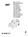
Simplicity 2691391-01 Kullanım kılavuzu
- Kategori
- Çim biçme makinaları
- Tip
- Kullanım kılavuzu
Bu kılavuz aynı zamanda aşağıdakiler için de uygundur:

Not for
Reproduction
80026844EST
B

Not for
Reproduction
1
2
3
4
5
6
7
8
9
10
2

Not for
Reproduction
11
12
13
14
15
16
17
18
19
20
3

Not for
Reproduction
21
22
23
24
25
4

Not for
Reproduction
Products Covered by This
Manual
The following products are covered by this manual:
2691351-00, 2691351-01, 2691352-00, 2691352-01,
2691353-00, 2691353-01, 2691353-02, 2691357-00,
2691357-01, 2691359-00, 2691359-01, 2691359-02,
2691391-00, 2691391-01, 2691395-00, 2691395-01,
2691410-00, 2691410-01, 2691411-00, 2691411-01,
2691412-00
Manual Contents:
Operator Safety.....................................................................5
Safety Interlock Systems Checks......................................10
Features and Controls........................................................11
Operation.............................................................................11
Maintenance.........................................................................16
Troubleshooting..................................................................19
Specifications......................................................................19
Save these instructions. This manual contains safety
information to make you aware of the hazards and risks
associated with the product and how to avoid them. It also
contains important instructions that should be followed during
the initial set-up, operation, and maintenance of the product.
Save these original instructions for future reference.
Note:
For instructions to install, remove, and level the mower
deck (including belt replacement), see the Mower Deck Manual
supplied with this machine.
Note:
The engine information contained in this manual applies
to Briggs & Stratton engines only. For information regarding
non-Briggs engines, refer to the engine manual supplied with
your unit.
The images in this document are representative, and are meant
to complement the instructional copy they accompany. Your
unit may vary from the images displayed.
LEFT
and
RIGHT
are
as seen from the operator's position.
Operator Safety
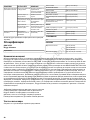
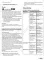
Safety Symbols And Meanings
StopShockMoving PartsFire
On / OffExplosionKickbackToxic Fumes
ChokeHot SurfaceHazardous
Chemical
Wear Eye
Protection
OilSlowFastRead Manual
Amputation
Hazard
Roll-Over HazardFuel Shut-OffFuel
Safety Alert Symbol and Signal Words
The safety alert symbol is used to identify safety information
about hazards that can result in personal injury. A signal word
(DANGER, WARNING, or CAUTION) is used with the alert
symbol to indicate the likelihood and the potential severity of
injury. In addition, a hazard symbol may be used to represent
the type of hazard.
DANGER indicates a hazard which, if not avoided, will
result in death or serious injury.
WARNING indicates a hazard which, if not avoided, could
result in death or serious injury.
CAUTION indicates a hazard which, if not avoided, could
result in minor or moderate injury.
NOTICE
indicates an situation that could result in damage
to the product.
Carbon Monoxide Warning
WARNING
Running engine gives off carbon monoxide, an odorless,
colorless, poison gas.
Breathing carbon monoxide can cause headache, fatigue,
dizziness, vomiting, confusion, seizures, nausea, fainting
or death.
• Operate equipment ONLY outdoors.
• Keep exhaust gas from entering a confined area through
windows, doors, ventilation intakes, or other openings.
5

Not for
Reproduction
General Operating Safety Instructions
WARNING
Read these safety rules and follow them closely. Failure to
obey these rules could result in loss of control of unit, severe
personal injury or death to you, or bystanders, or damage to
property or equipment. This mowing deck is capable of
amputating hands and feet and throwing objects. The
triangle in text signifies important cautions or warnings which
must be followed.
General Operation
1. Read, understand, and follow all instructions in the manual
and on the unit before starting.
2. Do not put hands or feet near rotating parts or under the
machine. Keep clear of the discharge opening at all times.
3. Only allow responsible adults, who are familiar with the
instructions, to operate the unit (local regulations can restrict
operator age).
4. Clear the area of objects such as rocks, toys, wire, etc.,
which could be picked up and thrown by the blade(s).
5. Be sure the area is clear of other people before mowing.
Stop the unit if anyone enters the area.
6. Never carry passengers.
7. Do not mow in reverse unless absolutely necessary. Always
look down and behind before and while traveling in reverse.
8. Never direct discharge material toward anyone. Avoid
discharging material against a wall or obstruction. Material
may ricochet back toward the operator. Stop the blade(s)
when crossing gravel surfaces.
9. Do not operate the machine without the entire grass catcher,
discharge guard (deflector), or other safety devices in place.
10. Slow down before turning.
11. Never leave a running unit unattended. Always disengage
the PTO, set parking brake, stop engine, and remove keys
before dismounting.
12. Disengage blades (PTO) when not mowing. Shut off engine
and wait for all parts to come to a complete stop before
cleaning the machine, removing the grass catcher, or
unclogging the discharge guard.
13. Operate the machine only in daylight or good artificial light.
14. Do not operate the unit while under the influence of alcohol
or drugs.
15. Watch for traffic when operating near or crossing roadways.
16. Use extra care when loading or unloading the unit into a
trailer or truck.
17. Always wear eye protection when operating this unit.
18. Data indicates that operators, age 60 years and above, are
involved in a large percentage of power equipment-related
injuries. These operators should evaluate their ability to
operate the equipment safely enough to protect themselves
and others from injury.
19. Follow the manufacturer’s recommendations for wheel
weights or counterweights.
20. Keep in mind the operator is responsible for accidents
occurring to other people or property.
21. All drivers should seek and obtain professional and practical
instruction.
22. Always wear substantial footwear and trousers. Never
operate when barefoot or wearing sandals.
23. Before using, always visually check that the blades and
blade hardware are present, intact, and secure. Replace
worn or damaged parts.
24. Disengage attachments before: refueling, removing an
attachment, making adjustments (unless the adjustment
can be made from the operator’s position).
25. When the machine is parked, stored, or left unattended,
lower the cutting means unless a positive mechanical lock
is used.
26. Before leaving the operator’s position for any reason,
disengage the PTO, engage the parking brake (if equipped),
stop the engine, and remove the key.
27. To reduce fire hazard, keep the unit free of grass, leaves,
& excess oil. Do not stop or park over dry leaves, grass, or
combustible materials.
28. It is a violation of California Public Resource Code Section
4442 to use or operate the engine on or near any
forest-covered, brush-covered, or grass-covered land unless
the exhaust system is equipped with a spark arrester
meeting any applicable local or state laws. Other states or
federal areas may have similar laws.
Transporting And Storage
1. When transporting the unit on an open trailer, make sure it
is facing forward, in the direction of travel. If the unit is facing
backwards, wind lift could damage the unit.
2. Always observe safe refueling and fuel handling practices
when refueling the unit after transportation or storage.
3. Never store the unit (with fuel) in an enclosed poorly
ventilated structure. Fuel vapors can travel to an ignition
source (such as a furnace, water heater, etc.) and cause
an explosion. Fuel vapor is also toxic to humans and
animals.
4. Always follow the engine manual instructions for storage
preparations before storing the unit for both short and long
term periods.
5. Always follow the engine manual instructions for proper
start-up procedures when returning the unit to service.
6. Never store the unit or fuel container inside where there is
an open flame or pilot light, such as in a water heater. Allow
unit to cool before storing.
6

Not for
Reproduction
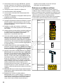
WARNING
Unsafe Operation Hazard
Do not load this zero-turn rider on a trailer or truck using two
separate ramps. Only use a single ramp that is at least one
foot wider than the width of the rear wheels of this rider. This
rider has a zero turning radius and the rear wheels could fall
off the ramps, or the rider could tip over injuring the operator
or bystanders.
Slope Operation
Slopes are a major factor related to loss-of-control and tipover
accidents, which can result in severe injury or death. Operation
on all slopes requires extra caution. If you feel uneasy on a
slope, do not operate on it.
Control of a walk-behind or ride-on machine sliding on a slope
will not be regained by the application of the brake. The main
reasons for loss of control are: insufficient tire grip on the ground,
speed too fast, inadequate braking, the type of machine is
unsuitable for its task, lack of awareness of the ground
conditions, incorrect hitching and load distribution.
1. Mow up and down slopes, not across.
2. Watch for holes, ruts, or bumps. Uneven terrain could
overturn the unit. Tall grass can hide obstacles.
3. Choose a slow speed so that you will not have to stop or
change speeds while on the slope.
4. Do not mow on wet grass. Tires may loose traction.
5. Always keep unit in gear especially when traveling down
slopes. Do not shift to neutral and coast downhill.
6. Avoid starting, stopping, or turning on a slope. If tires lose
traction, disengage the blade(s) and proceed slowly straight
down the slope.
7. Keep all movement on slopes slow and gradual. Do not
make sudden changes in speed or direction, which could
cause the machine to rollover.
8. Use extra care while operating machines with grass catchers
or other attachments; they can affect the stability of the unit.
Do not use on steep slopes.
9. Do not try to stabilize the machine by putting your foot on
the ground (ride-on units).
10. Do not mow near drop-offs, ditches, or embankments. The
mower could suddenly turn over if a wheel is over the edge
of a cliff or ditch, or if an edge caves in.
11. Do not use grass catchers on steep slopes.
12. Do not mow slopes you cannot back up.
13. See your authorized dealer/retailer for recommendations
of wheel weights or counterweights to improve stability.
14. Remove obstacles such as rocks, tree limbs, etc.
15. Use slow speed. Tires may lose traction on slopes even
through the brakes are functioning properly.
16. Do not turn on slopes unless necessary, and then, turn
slowly and gradually downhill, if possible.
WARNING
Unsafe Operation Hazard
Never operate on slopes greater than 17.6 percent (10°) which
is a rise of 3-1/2 feet (106 cm) vertically in 20 feet (607 cm)
horizontally.
When operating on slopes use additional wheel weights or
counterweights. See your dealer/retailer to determine which
weights are available and appropriate for your unit.
Select slow ground speed before driving onto slope. In addition
to front weights, use extra caution when operating on slopes
with rear-mounted grass catchers.
Mow UP and DOWN the slope, never across the face, use
caution when changing directions and DO NOT START OR
STOP ON SLOPE.
Towed Equipment (Ride-On Units)
1. Tow only with a machine that has a hitch designed for
towing. Do not attach towed equipment except at the hitch
point.
2. Follow the manufacturer’s recommendations for weight limit
for towed equipment and towing on slopes.
3. Never allow children or others in or on towed equipment.
4. On slopes, the weight of the towed equipment may cause
loss of traction and loss of control.
5. Travel slowly and allow extra distance to stop.
6. Do not shift to neutral and coast down hill.
Children
Tragic accidents can occur if the operator is not alert to the
presence of children. Children are often attracted to the unit
and the mowing activity. Never assume that children will remain
where you last saw them.
1. Keep children out of the mowing area and under the
watchful care of another responsible adult.
2. Be alert and turn unit off if children enter the area.
3. Before and during reverse operation, look behind and down
for small children.
4. Never carry children, even with the blade(s) off. They may
fall off and be seriously injured or interfere with safe unit
7

Not for
Reproduction
operation. Children who have been given rides in the past
may suddenly appear in the mowing area for another ride
and be run over or backed over by the machine.
5. Never allow children to operate the unit.
6. Use extra care when approaching blind corners, shrubs,
trees, or other objects that may obscure vision.
Emissions
1. Engine exhaust from this product contains chemicals known,
in certain quantities, to cause cancer, birth defects, or other
reproductive harm.
2. Look for the relevant Emissions Durability Period and Air
Index information on the engine emissions label.
Service And Maintenance
Safe Handling Of Gasoline
1. Extinguish all cigarettes, cigars, pipes, and other sources
of ignition.
2. Use only approved gasoline containers.
3. Never remove the gas cap or add fuel with the engine
running. Allow the engine to cool before refueling.
4. Never fuel the machine indoors.
5. Never store the machine or fuel container where there is
an open flame, spark, or pilot light such as near a water
heater or other appliance.
6. Never fill containers inside a vehicle or on a truck bed with
a plastic bed liner. Always place containers on the ground
away from your vehicle before filling.
7. Remove gas-powered equipment from the truck or trailer
and refuel it on the ground. If this is not possible, then refuel
such equipment on a trailer with a portable container, rather
than from a gasoline dispenser nozzle.
8. Keep nozzle in contact with the rim of the fuel tank or
container opening at all times until fueling is complete. Do
not use a nozzle lock-open device.
9. If fuel is spilled on clothing, change clothing immediately.
10. Never over-fill the fuel tank. Replace gas cap and tighten
securely.
11. Use extra care in handling gasoline and other fuels. They
are flammable and vapors are explosive.
12. If fuel is spilled, do not attempt to start the engine but move
the machine away from the area of spillage and avoid
creating any source of ignition until fuel vapors have
dissipated.
13. Replace all fuel tank caps and fuel container caps securely.
Service & Maintenance
1. Never run the unit in an enclosed area where carbon
monoxide fumes may collect.
2. Keep nuts and bolts, especially blade attachment bolts, tight
and keep equipment in good condition.
3. Never tamper with safety devices. Check their proper
operation regularly and make necessary repairs if they are
not functioning properly.
4. Keep unit free of grass, leaves, or other debris buildup.
Clean up oil or fuel spillage. and remove any fuel-soaked
debris. Allow machine to cool before storage.
5. If you strike an object, stop and inspect the machine. Repair,
if necessary, before restarting.
6. Never make adjustments or repairs with the engine running.
7. Check grass catcher components and the discharge guard
frequently and replace with manufacturer’s recommended
parts, when necessary.
8. Mower blades are sharp. Wrap the blade or wear gloves,
and use extra caution when servicing them.
9. Check brake operation frequently. Adjust and service as
required.
10. Maintain or replace safety and instructions labels, as
necessary.
11. Do not remove the fuel filter when the engine is hot as
spilled gasoline may ignite. Do not spread fuel line clamps
further than necessary. Ensure clamps grip hoses firmly
over the filter after installation.
12. Do not use gasoline containing METHANOL, gasohol
containing more than 10% ETHANOL, gasoline additives,
or white gas because engine/fuel system damage could
result.
13. If the fuel tank must be drained, it should be drained
outdoors.
14. Replace faulty silencers/mufflers.
15. Use only factory authorized replacement parts when making
repairs.
16. Always comply with factory specifications on all settings
and adjustments.
17. Only authorized service locations should be utilized for
major service and repair requirements.
18. Never attempt to make major repairs on this unit unless you
have been properly trained. Improper service procedures
can result in hazardous operation, equipment damage and
voiding of manufacturer’s warranty.
19. On multiple blade mowers, take care as rotating one blade
can cause other blades to rotate.
20. Do not change engine governor settings or over-speed the
engine. Operating the engine at excessive speed can
increase the hazard of personal injury.
21. Disengage drive attachments, stop the engine, remove the
key, and disconnect the spark plug wire(s) before: clearing
attachment blockages and chutes, performing service work,
striking an object, or if the unit vibrates abnormally. After
striking an object, inspect the machine for damage and
make repairs before restarting and operating the equipment.
8

Not for
Reproduction
22. Never place hands near the moving parts, such as a hydro
pump cooling fan, when the tractor is running. (Hydro pump
cooling fans are typically located on top of the transaxle).
23. Units with hydraulic pumps, hoses, or motors: WARNING:
Hydraulic fluid escaping under pressure may have sufficient
force to penetrate skin and cause serious injury. If foreign
fluid is injected into the skin it must be surgically removed
within a few hours by a doctor familiar with this form of injury
or gangrene may result. Keep body and hands away from
pin holes or nozzles that eject hydraulic fluid under high
pressure. Use paper or cardboard, and not hands, to search
for leaks. Make sure all hydraulic fluid connections are tight
and all hydraulic hoses and lines are in good condition
before applying pressure to the system. If leaks occur, have
the unit serviced immediately by your authorized dealer.
24. WARNING: Stored energy device. Improper release of
springs can result in serious personal injury. Springs should
be removed by an authorized technician.
25. Models equipped with an engine radiator: WARNING: Stored
energy device. To prevent serious bodily injury from hot
coolant or steam blow-out, never attempt to remove the
radiator cap while the engine is running. Stop the engine
and wait until it is cool. Even then, use extreme care when
removing the cap.
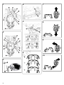
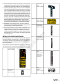
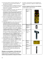
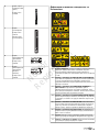
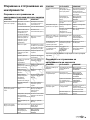
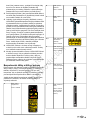
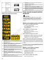
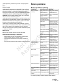
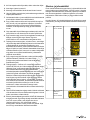
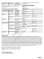
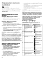
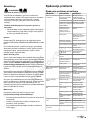
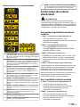
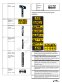
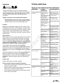
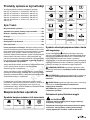
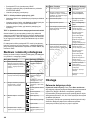
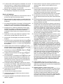
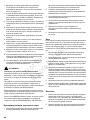
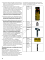
Safety and Instructional Decals
Before operating your unit, read and understand the safety and
instructional decals. Compare Figure 1 with the table following.
The cautions, warnings, and instructions are for your safety. To
avoid personal injury or damage to the unit, understand and
follow all the decals.
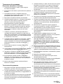
If any safety or instructional decals become worn or damaged,
and cannot be read, order replacement decals from your dealer.
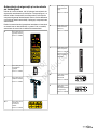
Decal, Main Safety
Part No. 1759648
A
Decal, Tracking
Adjustment
Part No. 1759724
B
Decal, Cutting
Height
Part No. 1759253
C
Decal, Danger,
Thrown Objects
Part No. 7106109
D, H
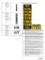
Decal, Engine
Speed (Choke)
Part No. 7105770
E
Decal, Engine
Speed (No Choke)
Part No. 7105868
E
Decal, Parking
Brake
Part No. 1760177
(Models with
manual parking
brake only)
F
Decal,
Transmission
Release
Part No. 1758366
G
9

Not for
Reproduction
Decal,
Transmission
Release
(Suspension
Models)
Part No. 1758366
G
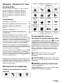
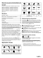
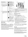
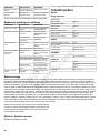
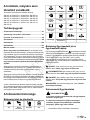
Safety Decal Icon Definitions
WARNING: Read and understand the Operator's Manual before using
this machine. Know the location and function of all controls. Do not
operate this machine unless you are trained.
A
DANGER - AMPUTATION AND DISMEMBERMENT HAZARD: To
avoid injury from rotating blades and moving parts, keep safety devices
(guards, shields and switches) in place and working.
B
DANGER - THROWN OBJECTS AND AMPUTATION HAZARD: To
avoid injury, keep bystanders and children away. Remove objects that
can be thrown by the blades. Do not mow without discharge chute or
entire grass catcher in place.
C
DANGER - TIPOVER / ROLLOVER HAZARD: Mow up and down
slopes, not across. Do not operate on slopes over 10 degrees. Slow
down when turning.
D
DANGER - AMPUTATION HAZARD: Never carry riders, especially
children, even with the blades off. Do not mow in reverse unless
absolutely necessary. Look down and behind - before and while
backing.
E
DANGER - CONTROL HAZARD: If traction is lost on slope, stop
forward movement, turn off PTO, and slowly back down slope.
F
DANGER: Engage parking brake, remove key, and consult technical
literature before performing service or maintenance.
G
DANGER - FIRE HAZARD: Remove key and wait three (3) minutes
before refueling.
H
DANGER - THROWN OBJECTS HAZARD: Do not mow without
discharge chute or entire grass catcher in place.
I
DANGER - THROWN OBJECTS AND AMPUTATION HAZARD: To
avoid injury from rotating blades, stay clear of deck edge and keep
others away.
J
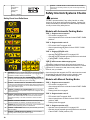
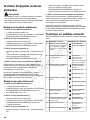
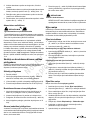
Safety Interlock Systems Checks
WARNING
DO NOT operate machine if any safety interlock or safety
device is not in place and functioning properly. Contact your
dealer immediately for assistance. DO NOT attempt to defeat,
modify or remove any safety device.
Models with Automatic Parking Brake
TEST 1 - Engine must not crank if:
• PTO switch is engaged, OR,
• Ground speed levers are not locked in their START / PARK
positions.
TEST 2 - Engine should crank if:
• PTO switch is NOT engaged, AND,
• Ground speed levers are locked in their START / PARK
positions.
TEST 3 - Engine must shut off if:
• Operator rises off seat with PTO engaged, OR
• Operator rises off seat with ground speed levers not locked
in their START / PARK positions.
TEST 4 - Check mower blade stopping time
The mower blades and mower drive belt should come to a
complete stop within five seconds after the electric PTO switch
is turned off. If mower drive belt does not stop within five
seconds, see your dealer.
Once the engine has stopped, the PTO switch must be turned
off, and the ground speed levers must be locked in their
START/PARK positions in order to start the engine.
Models with Manual Parking Brake
TEST 1 - Engine must not crank if:
• PTO switch is engaged, OR,
• Ground speed levers are not locked in their START / PARK
positions, OR,
• Parking brake is not engaged.
TEST 2 - Engine should crank if:
• PTO switch is NOT engaged, AND,
• Ground speed levers are locked in their START / PARK
positions, AND,
• Parking brake is engaged.
TEST 3 - Engine must shut off if:
• Operator rises off seat with PTO engaged, OR
• Operator rises off seat with ground speed levers not locked
in their START / PARK positions, OR,
10

Not for
Reproduction
• Operator rises off seat with parking brake not engaged.
TEST 4 - Check mower blade stopping time
The mower blades and mower drive belt should come to a
complete stop within five seconds after the electric PTO switch
is turned off. If mower drive belt does not stop within five
seconds, see your dealer.
Once the engine has stopped, the PTO switch must be turned
off, the parking brake must be engaged, and the ground speed
levers must be locked in their START/PARK positions in order
to start the engine.
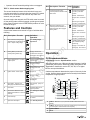
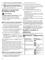
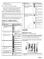
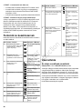
Features and Controls
Compare the features and controls in Figure 2 with the table
following.
Definition /
Operation
Icon(s)Description / FunctionRef.
See
Cutting Height
Adjustment
Deck Lift Pedal, Cutting Height
Adjustment Pin and Deck Lift Lock
Lever - adjusts cutting height
A
Engage - Move lever
forward and to the right
Disengage - Move lever to
the left and back
Parking Brake (models with
manual parking brake only)
B
Choke on (closed) - Briggs
engines only
Engine Speed Control - controls
engine speed
C
Engine speed fast
Engine speed slow
Engine offIgnition Switch - starts engineD
Engine on (run)
Engine start
PTO engage - pull up on
switch
PTO Switch - engages and
disengages mower blade clutch
E
Indicates total hours of
engine operation
Hour MeterF
See
Pushing the Unit by
Hand
Transmission Release Levers -
release transmissions so unit can
roll freely
G
Turn cap counterclockwise
to remove
Fuel Tank CapH
See
Seat Adjustments
Operator's Seat AdjustI
Definition /
Operation
Icon(s)Description / FunctionRef.
Forward ground speed
increase - push lever
forward
Neutral - release lever
Engine start - move lever
out
Reverse ground speed
increase - pull lever back
Left Ground Speed Lever -
controls speed and direction of left
drive wheel
J
Forward ground speed
increase - push lever
forward
Neutral - release lever
Engine start - move lever
out
Reverse ground speed
increase - pull lever back
Right Ground Speed Lever -
controls speed and direction of
right drive wheel; also engages
parking brake *
K
* Parking brake (models
with automatic parking
brake only)
Engage - move lever out
Disengage - move lever in
Operation
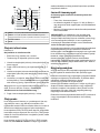
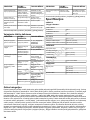
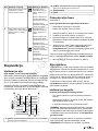
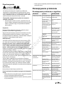
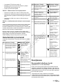
Oil Recommendations
Oil Capacity: See the
Specifications
section.
We recommend the use of Briggs & Stratton Warranty Certified
oils for best performance. Other high-quality detergent oils are
acceptable if classified for service SF, SG, SH, SJ or higher.
Do not use special additives.
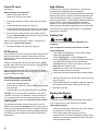
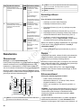
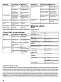
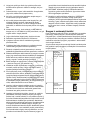
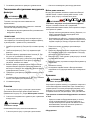
Outdoor temperatures determine the proper oil viscosity for the
engine. Use the chart to select the best viscosity for the outdoor
temperature range expected.
SAE 30 - Below 40 °F (4 °C) the use of SAE 30 will result in hard
starting.
A
10W-30 - Above 80 °F (27 °C) the use of 10W-30 may cause increased
oil consumption. Check oil level more frequently.
B
Synthetic 5W-30C
5W-30D
11

Not for
Reproduction
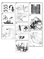
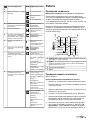
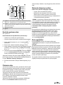
Check Oil Level
See Figure: 3
Before adding or checking the oil
• Make sure the engine is level.
• Clean the oil fill area of any debris.
1. Remove the dipstick (A, Figure 3) and wipe with a clean
cloth.
2. Install and tighten the dipstick (A, Figure 3).
3. Remove the dipstick and check the oil level. Correct oil level
is at the top of the full indicator (B, Figure 3) on the dipstick.
4. If oil level is low, slowly add oil into the engine oil fill (C,
Figure 3). Do not overfill. After adding oil, wait one minute
and then recheck the oil level.
Note:
Do not add oil at the quick oil drain , if equipped. For
location, see
Features and Controls.
5. Reinstall and tighten the dipstick (A, Figure 3).
Oil Pressure
If the oil pressure is too low, a pressure switch (if equipped) will
either stop the engine or activate a warning device on the
equipment. If this occurs, stop the engine and check the oil level
with the dipstick.
If the oil level is below the ADD mark, add oil until it reaches
the FULL mark. Start the engine and check for proper pressure
before continuing to operate.
If the oil level is between the ADD and FULL marks, do not
start the engine. Contact an authorized dealer to have the oil
pressure problem corrected.
Fuel Recommendations
Fuel must meet these requirements:
• Clean, fresh, unleaded gasoline.
• A minimum of 87 octane / 87 AKI (91 RON). For high altitude
use, see below.
• Gasoline with up to 10% ethanol (gasohol) is acceptable.
NOTICE
Do not use unapproved gasolines, such as E15
and E85. Do not mix oil in gasoline or modify the engine to
run on alternate fuels. Use of unapproved fuels will cause
damage to engine components, which will not be covered
under warranty.
To protect the fuel system from gum formation, mix a fuel
stabilizer into the fuel. See Storage. All fuel is not the same. If
starting or performance problems occur, change fuel providers
or change brands. This engine is certified to operate on gasoline.
The emissions control system for this engine is EM (Engine
Modifications).
High Altitude
At altitudes over 5,000 feet (1524 meters), a minimum 85
octane/85 AKI (89 RON) gasoline is acceptable.
For carbureted engines, high altitude adjustment is required to
maintain performance. Operation without this adjustment will
cause decreased performance, increased fuel consumption,
and increased emissions. Contact a Briggs & Stratton Authorized
Service Dealer for high altitude adjustment information.
Operation of the engine at altitudes below 2,500 feet (762
meters) with the high altitude adjustment is not recommended.
For Electronic Fuel Injection (EFI) engines, no high altitude
adjustment is necessary.
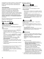
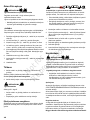
Adding Fuel
WARNING
Fuel and its vapors are extremely flammable and
explosive.
Fire or explosion can cause severe burns or death.
When Adding Fuel
• Turn engine off and let engine cool at least 3 minutes
before removing the fuel cap.
• Fill fuel tank outdoors or in well-ventilated area.
• Do not overfill fuel tank. To allow for expansion of the fuel,
do not fill above the bottom of the fuel tank neck.
• Keep fuel away from sparks, open flames, pilot lights,
heat, and other ignition sources.
• Check fuel lines, tank, cap, and fittings frequently for
cracks or leaks. Replace if necessary.
• If fuel spills, wait until it evaporates before starting engine.
1. Clean the fuel cap area of dirt and debris. Remove the fuel
cap (A, Figure 4).
2. Fill the fuel tank with fuel. To allow for expansion of the fuel,
do not fill above the bottom of the fuel tank neck (B).
3. Reinstall the fuel cap.
Starting the Engine
WARNING
Fuel and its vapors are extremely flammable and explosive.
Fire or explosion can cause severe burns or death.
When Starting Engine
• Ensure that spark plug, muffler, fuel cap, and air cleaner
(if equipped) are in place and secured.
• Do not crank engine with spark plug removed.
• If engine floods, set choke (if equipped) to OPEN / RUN
position, move throttle (if equipped) to FAST position and
crank until engine starts.
12

Not for
Reproduction
WARNING
Running engine gives off carbon monoxide, an odorless,
colorless, poison gas.
Breathing carbon monoxide can cause headache, fatigue,
dizziness, vomiting, confusion, seizures, nausea, fainting or
death.
• Operate equipment ONLY outdoors.
• Keep exhaust gas from entering a confined area through
windows, doors, ventilation intakes, or other openings.
WARNING
• If you do not understand how a specific control functions,
or have not yet thoroughly read the
Features & Controls
section, do so now.
• Do NOT attempt to operate the tractor without first
becoming familiar with the location and function of all
controls.
1. While sitting in the operator's seat:
• Models with automatic parking brake: Make sure the
PTO switch is disengaged and the ground speed control
levers are locked in the START/PARK position. (The
parking brake is automatically engaged when the
ground speed levers are locked in the START/PARK
position.)
• Models with manual parking brake: Make sure the
PTO switch is disengaged, the parking brake is
engaged, and the ground speed control levers are
locked in the START/PARK position.
2. Set the engine speed control past the FAST position to the
CHOKE position.
A warm engine does not require choking.
Some engines are equipped with a separate choke control.
Some engines are equipped with a ReadyStart
®
feature,
and do not feature a choke.
3. Insert the key into the ignition switch and turn it to START.
4. After the engine starts, turn off the choke (if equipped), and
warm up the engine by running it for at least a minute before
engaging the PTO switch or driving the rider.
5. After warming the engine, always operate the unit at full
engine speed when mowing.
In the event of an emergency the engine can be stopped
by simply turning the ignition switch to STOP.
Use this
method only in emergency situations. For normal engine shut
down follow the procedure given in
Stopping The Rider And
Engine
.
Stopping the Rider
1. Return the ground speed levers to the middle (or
neutral
‘N’
) position to stop rider movement. Pivot the levers
outward to lock them in the START/PARK position.
2. Engage the parking brake.
On models with an automatic parking brake, moving the
ground speed levers to the START/ PARK position
automatically engages the parking brake.
3. Disengage the PTO by pushing down on the PTO switch.
4. Move the engine speed control to the SLOW position and
turn the ignition switch to OFF. Remove the key.
Mowing
1. Make sure the PTO switch is disengaged, the ground speed
control levers are locked in their START/PARK positions,
and the operator is in the seat. On models with a manual
parking brake, make sure the parking brake is engaged.
2. Start the engine. See
Starting the Engine
.
3. Set the mower cutting height. See
Cutting Height
Adjustment
.
4. Set the engine speed control to FAST.
5. Engage the PTO by pulling up on the PTO switch.
6. Pivot the ground speed levers in from the START/PARK
position to the neutral ‘N’ position.
7. Begin mowing. See
Operator Safety
for tips on safe
mowing practices.
8. When finished, shut off the PTO.
9. Stop the engine. See
Stopping The Rider And Engine
.
Pushing the Rider By Hand
WARNING
Unsafe Operation Hazard.
DO NOT disengage the transmissions and coast down slopes.
DO NOT use Roll Release to disengage the transmissions
unless machine motion can be controlled and engine is off.
NOTICE
Do not tow rider. Towing the unit will cause transmission
damage. Do not use another vehicle to push or pull this unit.
1. Disengage the PTO, lock the ground speed levers into their
START/PARK positions, turn the ignition OFF, remove the
key, and wait for all moving parts to stop. On models with
a manual parking brake, engage the parking brake.
2. To disengage the transmissions, move the roll release levers
(A or B, Figure 5, depending on model), into the PUSH
position as shown.
3. Disengage the parking brake. On models with an automatic
parking brake, pivot the ground speed levers in from the
13

Not for
Reproduction
START/ PARK position to the neutral ‘N’ position to
disengage the parking brake.
4. The rider can now be pushed by hand.
5. After moving the rider, re-engage the transmissions by
moving the roll release levers back to the DRIVE position.
Driving
Zero Turn Driving Practice
Before attempting to drive the zero-turn riding mower make sure
you have read the
Features and Controls
section and
understand the location and function of all of the unit’s controls.
The ground speed control levers of this zero-turn riding mower
are responsive, and learning to gain a smooth and efficient
control of the unit’s forward, reverse, and turning movements
will take some practice.
Spending some time going through the maneuvers shown and
becoming familiar with how the unit accelerates, travels, and
steers, before you begin mowing, is absolutely essential to
getting the most out of the zero-turn riding mower.
Locate a smooth, flat area of your lawn, one with plenty of room
to maneuver. Clear the area of objects, people, and animals
before you begin. Operate the unit at mid-throttle during this
practice session (ALWAYS operate at full throttle when mowing),
and turn slowly to prevent tire slippage and damage to your
lawn.
We suggest you begin with the
Smooth Travel
procedure, and
then advance through the forward, reverse, and turning
maneuvers.
Smooth Travel
The lever controls of the Zero Turn rider are responsive.
The BEST method of handling the ground speed control levers
is in three steps — as shown in Figure 6.
FIRST place your hands onto the levers as shown.
SECOND, to go forward gradually push the levers forward with
your palms.
THIRD, to speed up move the levers farther forward. To slow
down smoothly, slowly move the levers toward neutral.
Basic Driving
Forward Travel Practice
Gradually move both ground speed control levers — evenly
FORWARD from neutral. Slow down and repeat.
NOTE: Straight forward travel takes practice. If necessary, top
speed can be balance-adjusted — see the Speed Balancing
Adjustment in the Adjustments section near the back of this
manual.
Reverse Travel Practice
LOOK DOWN & BEHIND, then gradually move both ground
speed control levers evenly BACK from neutral. Slow down and
repeat.
NOTE: Practice backing up for several minutes before
attempting to do so near objects. The rider turns sharply in
reverse as well as forward, and backing up straight takes
practice.
Practice Turning Around A Corner
While traveling forward allow one handle to gradually return
back toward neutral. Repeat several times.
NOTE: To prevent pivoting directly on the tire tread, it is best
to keep both wheels going at least slightly forward.
Practice Turning in Place
To turn in place, “Zero Turn,” gradually move one ground speed
control lever forward from neutral and one lever back from
neutral simultaneously. Repeat several times.
NOTE: Changing the amount each lever is pulled—forward or
back, changes the “pivot point” you turn on.
Advanced Driving
Executing an End-Of-Row Zero Turn
Your Zero Turn Rider’s unique ability to turn in place allows you
to turn around at the end of a cutting row rather than having to
stop and Y-turn before starting a new row.
For example, to execute a left end-of row zero turn:
1. Slow down at the end of the row.
2. Move the RIGHT ground speed control lever forward slightly
while moving the LEFT ground speed control lever back to
center and then slightly back from center.
3. Begin mowing forward again.
This technique turns the rider LEFT and slightly overlaps the
row just cut —eliminating the need to back up and re-cut missed
grass.
As you become more familiar and experienced with operating
the Zero Turn rider, you will learn more maneuvers that will
make your mowing time easier and more enjoyable.
Remember, the more you practice, the better your control
of the Zero Turn will be!
Attaching a Trailer
Secure the trailer with an appropriately sized clevis pin (A, Figure
12) and clip (B). See
Operator Safety
for additional safety
information regarding trailers and towing.
WARNING
Towing Hazard
Towed loads can be hazardous and cause loss of control on
slopes.
• The max gross (trailer & load) weight of trailer is 200 lbs
(91kg).
• Do not operate on slope exceeding 5 degrees.
• Reduce speed and use extreme caution on slopes.
14

Not for
Reproduction
Cutting Height Adjustment
The cutting height adjust pedal adjusts the mower cutting height.
See
Specifications
for cutting height adjustment range.
To adjust cutting height:
1. Fully depress the cutting height adjust pedal (A, Figure 13)
until the transport release rod (B) locks the deck into the
highest position (transport position).
2. Remove the pin (C, Figure 13) from the adjustment bracket,
and insert it in the desired hole.
Note:
Make sure the pin is inserted into the holes in both upper
and lower plates of the adjustment bracket.
3. Depress the cutting height adjust pedal, move the transport
release rod outward, and slowly release the pedal until it
rests against the pin.
Mower Removal And Installation
Refer to the Mower Deck Manual for instructions on removing
and installing the mower deck.
Mower Deck Leveling
Refer to the Mower Deck Manual for instructions on leveling
the mower deck.
Cargo Bed (select models)
The cargo bed is designed to carry up to 50 lbs (22,7 kg). Slots
in the rear of the bed will accommodate a 2 x 4 or 2 x 6 to help
secure loads during transport.
WARNING
Amputation Hazard
Rotating blades cut off arms and legs. Do not carry riders
(especially children) even with the blades off. They may fall
off or return for another ride when you are not expecting it.
WARNING
Loss of Control and Roll-Over Hazard
Operating with loads in the cargo bed greater than 50 lbs can
be hazardous and cause loss of control and roll-overs.
The cargo bed can be raised to access the engine compartment
without removing it.
To raise the cargo bed
1. Raise the seat (A, Figure 14).
2. Pull up firmly on the rear of the bed (B, Figure 14).
3. When lowering the bed, press down firmly to secure the
rear of the bed in place with the locking clips (D).
To remove the cargo bed
1. Remove the pins (C, Figure 14) securing the front of the
bed to the rider frame.
2. Pull up firmly on the rear of the bed to release the locking
clips (D, Figure 14).
3. Lift and remove the cargo bed from the rider.
CAUTION
To avoid injury, assistance is required when removing or
installing the cargo bed.
To install the cargo bed
1. Position the bed over the engine compartment, aligning the
holes in the front of the bed with the holes in the frame
brackets.
2. Install the pins (C, Figure 14) into the holes.
3. Lower the rear of the bed, pressing down firmly to secure
with the locking clips (D, Figure 14).
CAUTION
To avoid injury, assistance is required when removing or
installing the cargo bed.
Suspension Adjustment (if equipped)
The shock assemblies (A, Figure 15 - front shown, rear similar)
can be adjusted to vary the amount of pre-load applied to the
springs. This allows the operator to customize the ride according
to operator’s weight and operating conditions.
Less Pre-Load:
• Light operator weight
• Softer, more cushioned ride
• Best for relatively flat terrain
More Pre-Load:
• Heavy operator weight
• Stiffer, more rigid ride
• Better handling and greater stability on hilly terrain
To Adjust the Spring Pre-Load:
1. Park machine on a flat, level surface. Disengage the PTO,
pivot the ground speed levers out to the START/ PARK
position, and stop the engine.
2. Turn the pre-load adjustment collar (B, Figure 15) to a higher
notch (-) to decrease the pre-load, or to a lower notch (+)
to increase the pre-load. Make sure all shocks are set to
the same amount of pre-load.
15

Not for
Reproduction
Maintenance
Maintenance Schedule
WARNING
Unintentional sparking can result in fire or electric shock.
Unintentional start-up can result in entanglement, traumatic
amputation, or laceration.
Before performing adjustments or repairs:
• Disconnect the spark plug wire and keep it away from the
spark plug.
• Disconnect battery at negative terminal (only engines with
electric start).
• Use only correct tools.
• Do not tamper with governor spring, links, or other parts
to increase engine speed.
• Replacement parts must be of the same design and
installed in the same position as the original parts. Other
parts may not perform as well, may damage the unit, and
may result in injury.
• Do not strike the flywheel with a hammer or hard object
because the flywheel may shatter during operation.
TRACTOR AND MOWER
Every 8 Hours or Daily
Check safety interlock system
Clean debris off tractor and mower deck
Clean debris from engine compartment
Every 25 Hours or Annually *
Check mower blade stopping time
Check tractor and mower for loose hardware
Check tire pressure
Every 50 Hours or Annually *
Check tractor brakes
Clean battery and cables
See Dealer Annually to
Lubricate tractor and mower
Check mower blades **
* Whichever comes first
** Check blades more often in regions with sandy soils or high
dust conditions.
ENGINE
First 5 Hours
Change engine oil
Every 8 Hours or Daily
Check engine oil level
Every 25 Hours or Annually *
Clean engine air filter and pre-cleaner **
Every 50 Hours or Annually *
ENGINE
Change engine oil
Replace oil filter
Annually
Replace air filter
Replace pre-cleaner
See Dealer Annually to
Inspect muffler and spark arrester
Replace spark plug
Replace fuel filter
Clean engine air cooling system
* Whichever comes first
** Clean more often in dusty conditions or when airborne debris
is present.
Checking Tire Pressures
Tire pressure should be checked periodically (see Figure 16),
and maintained at the levels shown in the
Specifications
chart.
Note that these pressures may differ slightly from the "Max
Inflation" stamped on the side-wall of the tires. The pressures
shown provide proper traction and extend tire life.
Check Mower Blade Stopping Time
Mower blades and mower drive belt should come to a complete
stop within five seconds after the electric PTO switch is turned
off.
WARNING
Unsafe Operation Hazard
If the mower blade does not come to a complete stop within
5 seconds, the blade must be adjusted. Do not operate the
machine until the proper adjustment has been performed by
an authorized dealer.
Check the mower blade for proper function. See Safety Interlock
System Tests. The blade should stop rotating in 5 seconds or
less after moving the blade control to the OFF position.
Battery Maintenance
WARNING
Explosion and Fire Hazard
When removing or installing battery cables, disconnect the
negative cable FIRST and reconnect it LAST. If not done in
this order, the positive terminal can be shorted to the frame
by a tool.
Cleaning the Battery and Cables
1. Disconnect the cables from the battery, negative cable first
(B, Figure 17).
16

Not for
Reproduction
2. Clean the battery terminals and cable ends with a wire brush
until shiny.
3. Reinstall the battery and reattach the battery cables, positive
cable first (A, Figure 17).
4. Coat the cable ends and battery terminals with petroleum
jelly or non-conducting grease.
5. Be sure to replace the terminal cover over the positive
battery terminal (A, Figure 17.
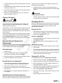
Charging The Battery
WARNING
Explosion and Fire Hazard
Keep open flames and sparks away from the battery; the
gasses coming from it are highly explosive. Ventilate the
battery well during charging.
A dead battery or one too weak to start the engine may be the
result of a defect in the charging system or other electrical
component. If there is any doubt about the cause of the problem,
see your dealer.
To charge the battery, follow the instructions provided by the
battery charger manufacturer as well as all warnings included
in the
Operator Safety
section of this manual. Charge the
battery until fully charged. Do not charge at a rate higher than
10 amps.
Seat And Ground Speed Lever
Adjustments
The seat and ground speed levers should be adjusted so that
the ground speed levers can be moved through their full range
of motion without contacting the operator’s legs.
Seat Adjustment
1. Raise the seat.
2. Loosen the adjustment hardware (A or B, Figure 18,
depending on seat type) under the seat base.
3. Slide the seat forward or backward to the desired position.
4. Tighten the hardware to 80 lb-in (9 Nm).
Ground Speed Lever Adjustment
1. Loosen the ground speed lever mounting hardware (A,
Figure 19) to adjust the levers forward and backward.
2. Remove the hardware to raise or lower the levers.
3. Always be sure to adjust both levers so that they are aligned
(B, Figure 19).
4. After adjustment is complete, tighten the hardware to 13
lb-ft (18 Nm).
Speed Balancing (Tracking) Adjustment
If the rider drifts to the right or left when the ground speed levers
are in the maximum forward position, the top speed of each of
these levers can be balanced. Only adjust the speed of the
wheel that is traveling faster.
1. Tighten the knob (A, Figure 20) of the faster wheel by
1/2-turn (clockwise) increments until the rider travels (tracks)
straight.
WARNING
Unsafe Operation Hazard
DO NOT adjust the rider for a faster overall speed forward
or reverse than it was designed.
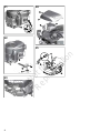
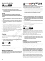
Changing The Oil
Used oil is a hazardous waste product and must be disposed
of properly. Do not discard with household waste. Check with
your local authorities, service center, or dealer for safe
disposal/recycling facilities.
Draining The Oil
1. With engine off but still warm, disconnect the spark plug
wire (A, Figure 21) and keep it away from the spark plug.
2. Remove the dipstick (B, Figure 21).
Standard Oil Drain Plug
1. Remove the oil drain plug (C, Figure 21). Drain the oil into
an approved container.
2. After the oil has drained, install and tighten the oil drain
plug.
Optional Quick Oil Drain
1. Disconnect the oil drain hose (H, Figure 22) from the side
of the engine.
2. Turn and remove the oil drain cap (I, Figure 22). Carefully
lower the quick oil drain (H) into an approved container (J).
3. After the oil has drained, install the oil drain cap. Attach the
oil drain hose to the side of the engine.
Changing The Oil Filter
For replacement intervals, see
Maintenance Schedule.
1. Drain the oil from the engine. See
Draining The Oil
.
2. Remove the oil filter (K, Figure 23) and dispose of properly.
3. Before installing the new oil filter, lightly lubricate the oil
filter gasket with fresh, clean oil.
4. Install the oil filter by hand until the gasket contacts the oil
filter adapter, then tighten the oil filter 1/2 to 3/4 turns.
5. Add oil. See
Operation
-
Check Oil Level
.
6. Start and run the engine. As the engine warms up, check
for oil leaks.
7. Stop the engine and check the oil level.
17

Not for
Reproduction
Servicing The Air Filter
WARNING
Fire and Explosion Hazard
Fuel and its vapors are extremely flammable and explosive.
Fire or explosion can cause severe burns or death.
• Never start or run the engine with the air cleaner assembly
or air filter removed.
NOTICE
Do not use pressurized air or solvents to clean the filter.
Pressurized air can damage the filter and solvents will dissolve
the filter.
1. Loosen the fasteners (A, Figure 24) and remove the cover
(B).
2. To remove the filter (C, Figure 24), lift the end of the filter.
3. Remove the pre-cleaner (D, Figure 24), if equipped, from
the filter.
4. To loosen debris, gently tap the filter on a hard surface. If
the filter is excessively dirty, replace with a new filter.
5. Wash the pre-cleaner in liquid detergent and water. Then
allow it to thoroughly air dry. Do not oil the precleaner.
6. Assemble the dry pre-cleaner to the filter.
7. Install the filter into the engine base (E, Figure 24) and push
down until the filter snaps in place.
8. Install the cover.
Cleaning
1. Clean dirt and debris from the rider and mower deck.
Note:
Some mower decks feature a washout port. See
Washing
The Mower Deck
.
2. Clean any debris buildup in the engine compartment and
from on or around the engine.
WARNING
Fire Hazard
Yard debris is combustible.
• Clean dirt and debris from the rider and mower deck.
• Clean build-up from around the engine.
Washing The Mower Deck
The washout port allows you to connect a typical garden hose
to the left-hand side of the mower deck to remove grass and
debris from the underside.
WARNING
Amputation and Thrown Object Hazard
Contact with the mower blades, or with objects thrown by the
mower blades, could result in death or serious injury.
• Before running the mower, make sure the hose is properly
connected and does not come into contact with the blades.
• When the mower is running and the blades are engaged,
the person cleaning the mower deck must be in the
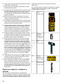
operator position, with no bystanders in the area.
1. Place the unit on a smooth level surface.
2. Attach the quick disconnect (A, Figure 25) to garden hose
(B) and connect to the washout port (C) on the mower deck.
3. Run water to remove grass and debris from the underside
of the mower deck.
4. Turn the mower on and place in the highest cutting position.
5. Turn the mower off.
6. Remove the garden hose and quick disconnect from the
washout port when completed.
Storage
WARNING
Fire and Explosion Hazard
Never store the unit (with fuel) in an enclosed, unventilated
structure. Fuel vapors can travel to an ignition source (such
as a furnace, water heater, etc.) and cause an explosion. Fuel
vapor is also toxic to humans and animals.
When Storing Fuel Or Equipment With Fuel in Tank
• Store away from furnaces, stoves, water heaters, or other
appliances that have pilot lights or other ignition sources
because they can ignite fuel vapors.
Equipment
Disengage the PTO, lock the ground speed levers in the
START/PARK position, and remove the key.
Battery life will be increased if it is removed. Put in a cool, dry
place and keep fully charged during storage. If the battery is
left in the unit, disconnect the negative cable.
Fuel System
Fuel can become stale when stored over 30 days. Stale fuel
causes acid and gum deposits to form in the fuel system or on
essential carburetor parts. To keep fuel fresh, use Briggs &
Stratton® Advanced Formula Fuel Treatment & Stabilizer,
available wherever Briggs & Stratton genuine service parts are
sold.
There is no need to drain gasoline from the engine if a fuel
stabilizer is added according to instructions. Run the engine for
2 minutes to circulate the stabilizer throughout the fuel system.
The engine and fuel can then be stored up to 24 months.
18

Not for
Reproduction
If gasoline in the tank has not been treated with a fuel stabilizer,
it must be drained into an approved container. Run the engine
until it stops from lack of fuel. The use of a fuel stabilizer in the
storage container is recommended to maintain freshness.
Engine Oil
While the engine is still warm, change the engine oil.
Before starting the unit after it has been stored:
• Check all fluid levels. Check all maintenance items.
• Perform all recommended checks and procedures found in
this manual.
• Allow the engine to warm up for several minutes before use.
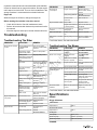
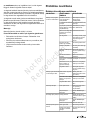
Troubleshooting
Troubleshooting The Rider
REMEDYLOOK FORPROBLEM
Lock ground speed
levers in START/ PARK
positions.
Ground speed levers not
in START/PARK
positions.
Engine will not turnover
or start.
Place in OFF position.PTO (electric clutch)
switch in ON position.
Engage parking brakeParking brake
disengaged (models with
manual parking brake
only)
If engine is hot, allow it to
cool, then refill the fuel
tank.
Out of fuel.
Open fuel valve.Fuel valve closed (if
equipped).
Open the choke (if
equipped).
Engine flooded.
Drain fuel and replace
with fresh fuel.
Gas is old or stale.
Clean the battery
terminals.
Battery terminals require
cleaning.
Recharge or replace.Battery discharged or
dead.
Clean and gap or
replace.
Spark plug(s) faulty,
fouled or incorrectly
gapped.
Drain fuel and refill with
fresh fuel.
Water in fuel.
Clean air filter. Check the
choke (if equipped).
Fuel mixture too rich.Engine starts hard or
runs poorly.
Clean and gap or
replace.
Spark plug faulty, fouled,
or incorrectly gapped.
Replace fuel filter.Fuel filter dirty.
Check/add oil as
required.
Low oil level.Engine knocks.
See
Oil
Recommendations
.
Using wrong grade oil.
REMEDYLOOK FORPROBLEM
Check engine fins,
blower screen, and air
cleaner.
Engine running too hot.Excessive oil
consumption.
See
Oil
Recommendations
.
Using wrong grade oil.
Drain excess oil.Too much oil in
crankcase.
Replace air filter.Dirty air filter.Engine exhaust is black.
Open choke control (if
equipped).
Engine choke control is
in closed position.
Unlock roll release
lever(s).
Transmission(s)
disengaged.
Engine runs, but rider will
not drive.
Clean as required.Pulleys or belt greasy or
oily.
Rider drive belt slips.
Check and tighten any
loose connections.
Steering linkage is loose.Rider steers or handles
poorly.
For all other issues, see authorized dealer.
Troubleshooting The Mower
REMEDYLOOK FORPROBLEM
See
Mower Removal
And Installation
.
Mower deck not properly
installed.
Mower will not raise.
See
Mower Deck
Leveling
.
Mower not leveled
properly.
Mower cut is uneven.
See
Maintenance
section.
Rider tires not inflated
equally or properly.
See engine speed control
to FAST.
Engine speed too slow.Mower cut is rough
looking.
Decrease ground speed.Ground speed too fast.
Set engine speed control
to FAST.
Engine speed too slow.Engine stalls easily with
mower engaged.
Decrease ground speed.Ground speed too fast.
Cut tall grass at
maximum cutting height
during first pass.
Cutting height set too
low.
Cut grass with discharge
pointing toward
previously cut area.
Discharge chute jamming
with cut grass.
Tighten to 50-60 ft-lbs
(68-81 Nm).
Blade mounting hardware
is loose.
Excessive mower
vibration.
For all other issues, see authorized dealer.
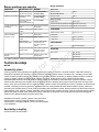
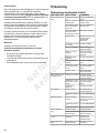
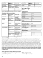
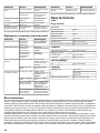
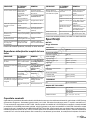
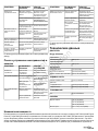
Specifications
ENGINE
Briggs & Stratton
Intek™ Series
656 ccDisplacement
Professional Series™
724 ccDisplacement
All Engines
64 oz (1,9 L)Oil Capacity
0.030 in. (0,76 mm)Spark Plug Gap
180 in-lbs (20 Nm)Spark Plug Torque
CHASSIS
19

Not for
Reproduction
3 gal (11,4 L)Fuel Tank Capacity
Inflation Pressure
22 psi (1,52 bar)- Front Wheels
12 psi (0,83 bar)- Rear Wheels
TRANSMISSION
Hydro-Gear® EZT®Type
MOWER
42” (107 cm)Width of Cut
46” (117 cm)
48” (122 cm)
1.5” - 4.5” (3,8 - 11,7 cm)Cutting Height
Power Ratings
The gross power rating for individual gasoline engine models is labeled in accordance with SAE (Society of Automotive Engineers)
code J1940 Small Engine Power & Torque Rating Procedure, and is rated in accordance with SAE J1995. Torque values are
derived at 2600 RPM for those engines with “rpm” called out on the label and 3060 RPM for all others; horsepower values are
derived at 3600 RPM. The gross power curves can be viewed at www.BRIGGSandSTRATTON.COM. Net power values are
taken with exhaust and air cleaner installed whereas gross power values are collected without these attachments. Actual gross
engine power will be higher than net engine power and is affected by, among other things, ambient operating conditions and
engine-to-engine variability. Given the wide array of products on which engines are placed, the gasoline engine may not develop
the rated gross power when used in a given piece of power equipment. This difference is due to a variety of factors including,
but not limited to, the variety of engine components (air cleaner, exhaust, charging, cooling, carburetor, fuel pump, etc.), application
limitations, ambient operating conditions (temperature, humidity, altitude), and engine-to-engine variability. Due to manufacturing
and capacity limitations, Briggs & Stratton may substitute an engine of higher rated power for this engine.
Note:
The engine information contained in this manual applies
to Briggs & Stratton engines only. For information regarding
non-Briggs engines, refer to the engine manual supplied with
your unit.
Parts And Accessories
See an Authorized Service Dealer.
20
Sayfa yükleniyor...
Sayfa yükleniyor...
Sayfa yükleniyor...
Sayfa yükleniyor...
Sayfa yükleniyor...
Sayfa yükleniyor...
Sayfa yükleniyor...
Sayfa yükleniyor...
Sayfa yükleniyor...
Sayfa yükleniyor...
Sayfa yükleniyor...
Sayfa yükleniyor...
Sayfa yükleniyor...
Sayfa yükleniyor...
Sayfa yükleniyor...
Sayfa yükleniyor...
Sayfa yükleniyor...
Sayfa yükleniyor...
Sayfa yükleniyor...
Sayfa yükleniyor...
Sayfa yükleniyor...
Sayfa yükleniyor...
Sayfa yükleniyor...
Sayfa yükleniyor...
Sayfa yükleniyor...
Sayfa yükleniyor...
Sayfa yükleniyor...
Sayfa yükleniyor...
Sayfa yükleniyor...
Sayfa yükleniyor...
Sayfa yükleniyor...
Sayfa yükleniyor...
Sayfa yükleniyor...
Sayfa yükleniyor...
Sayfa yükleniyor...
Sayfa yükleniyor...
Sayfa yükleniyor...
Sayfa yükleniyor...
Sayfa yükleniyor...
Sayfa yükleniyor...
Sayfa yükleniyor...
Sayfa yükleniyor...
Sayfa yükleniyor...
Sayfa yükleniyor...
Sayfa yükleniyor...
Sayfa yükleniyor...
Sayfa yükleniyor...
Sayfa yükleniyor...
Sayfa yükleniyor...
Sayfa yükleniyor...
Sayfa yükleniyor...
Sayfa yükleniyor...
Sayfa yükleniyor...
Sayfa yükleniyor...
Sayfa yükleniyor...
Sayfa yükleniyor...
Sayfa yükleniyor...
Sayfa yükleniyor...
Sayfa yükleniyor...
Sayfa yükleniyor...
Sayfa yükleniyor...
Sayfa yükleniyor...
Sayfa yükleniyor...
Sayfa yükleniyor...
Sayfa yükleniyor...
Sayfa yükleniyor...
Sayfa yükleniyor...
Sayfa yükleniyor...
Sayfa yükleniyor...
Sayfa yükleniyor...
Sayfa yükleniyor...
Sayfa yükleniyor...
Sayfa yükleniyor...
Sayfa yükleniyor...
Sayfa yükleniyor...
Sayfa yükleniyor...
Sayfa yükleniyor...
Sayfa yükleniyor...
Sayfa yükleniyor...
Sayfa yükleniyor...
Sayfa yükleniyor...
Sayfa yükleniyor...
Sayfa yükleniyor...
Sayfa yükleniyor...
Sayfa yükleniyor...
Sayfa yükleniyor...
Sayfa yükleniyor...
Sayfa yükleniyor...
Sayfa yükleniyor...
Sayfa yükleniyor...
Sayfa yükleniyor...
Sayfa yükleniyor...
Sayfa yükleniyor...
Sayfa yükleniyor...
Sayfa yükleniyor...
Sayfa yükleniyor...
Sayfa yükleniyor...
Sayfa yükleniyor...
Sayfa yükleniyor...
Sayfa yükleniyor...
Sayfa yükleniyor...
Sayfa yükleniyor...
Sayfa yükleniyor...
Sayfa yükleniyor...
Sayfa yükleniyor...
Sayfa yükleniyor...
Sayfa yükleniyor...
Sayfa yükleniyor...
Sayfa yükleniyor...
Sayfa yükleniyor...
Sayfa yükleniyor...
Sayfa yükleniyor...
Sayfa yükleniyor...
Sayfa yükleniyor...
Sayfa yükleniyor...
Sayfa yükleniyor...
Sayfa yükleniyor...
Sayfa yükleniyor...
Sayfa yükleniyor...
Sayfa yükleniyor...
Sayfa yükleniyor...
Sayfa yükleniyor...
Sayfa yükleniyor...
Sayfa yükleniyor...
Sayfa yükleniyor...
Sayfa yükleniyor...
Sayfa yükleniyor...
Sayfa yükleniyor...
Sayfa yükleniyor...
Sayfa yükleniyor...
Sayfa yükleniyor...
Sayfa yükleniyor...
Sayfa yükleniyor...
Sayfa yükleniyor...
Sayfa yükleniyor...
Sayfa yükleniyor...
Sayfa yükleniyor...
Sayfa yükleniyor...
Sayfa yükleniyor...
Sayfa yükleniyor...
Sayfa yükleniyor...
Sayfa yükleniyor...
Sayfa yükleniyor...
Sayfa yükleniyor...
Sayfa yükleniyor...
Sayfa yükleniyor...
Sayfa yükleniyor...
Sayfa yükleniyor...
Sayfa yükleniyor...
Sayfa yükleniyor...
Sayfa yükleniyor...
Sayfa yükleniyor...
Sayfa yükleniyor...
Sayfa yükleniyor...
Sayfa yükleniyor...
Sayfa yükleniyor...
Sayfa yükleniyor...
Sayfa yükleniyor...
Sayfa yükleniyor...
Sayfa yükleniyor...
Sayfa yükleniyor...
Sayfa yükleniyor...
Sayfa yükleniyor...
Sayfa yükleniyor...
Sayfa yükleniyor...
Sayfa yükleniyor...
Sayfa yükleniyor...
Sayfa yükleniyor...
Sayfa yükleniyor...
Sayfa yükleniyor...
Sayfa yükleniyor...
Sayfa yükleniyor...
Sayfa yükleniyor...
Sayfa yükleniyor...
Sayfa yükleniyor...
Sayfa yükleniyor...
Sayfa yükleniyor...
Sayfa yükleniyor...
Sayfa yükleniyor...
Sayfa yükleniyor...
Sayfa yükleniyor...
Sayfa yükleniyor...
Sayfa yükleniyor...
Sayfa yükleniyor...
Sayfa yükleniyor...
Sayfa yükleniyor...
Sayfa yükleniyor...
Sayfa yükleniyor...
Sayfa yükleniyor...
Sayfa yükleniyor...
Sayfa yükleniyor...
Sayfa yükleniyor...
Sayfa yükleniyor...
Sayfa yükleniyor...
Sayfa yükleniyor...
Sayfa yükleniyor...
Sayfa yükleniyor...
Sayfa yükleniyor...
Sayfa yükleniyor...
Sayfa yükleniyor...
Sayfa yükleniyor...
Sayfa yükleniyor...
Sayfa yükleniyor...
Sayfa yükleniyor...
Sayfa yükleniyor...
Sayfa yükleniyor...
Sayfa yükleniyor...
Sayfa yükleniyor...
Sayfa yükleniyor...
Sayfa yükleniyor...
Sayfa yükleniyor...
Sayfa yükleniyor...
Sayfa yükleniyor...
Sayfa yükleniyor...
Sayfa yükleniyor...
Sayfa yükleniyor...
Sayfa yükleniyor...
Sayfa yükleniyor...
Sayfa yükleniyor...
Sayfa yükleniyor...
Sayfa yükleniyor...
Sayfa yükleniyor...
Sayfa yükleniyor...
Sayfa yükleniyor...
Sayfa yükleniyor...
Sayfa yükleniyor...
Sayfa yükleniyor...
Sayfa yükleniyor...
Sayfa yükleniyor...
Sayfa yükleniyor...
Sayfa yükleniyor...
Sayfa yükleniyor...
Sayfa yükleniyor...
Sayfa yükleniyor...
Sayfa yükleniyor...
Sayfa yükleniyor...
-
 1
1
-
 2
2
-
 3
3
-
 4
4
-
 5
5
-
 6
6
-
 7
7
-
 8
8
-
 9
9
-
 10
10
-
 11
11
-
 12
12
-
 13
13
-
 14
14
-
 15
15
-
 16
16
-
 17
17
-
 18
18
-
 19
19
-
 20
20
-
 21
21
-
 22
22
-
 23
23
-
 24
24
-
 25
25
-
 26
26
-
 27
27
-
 28
28
-
 29
29
-
 30
30
-
 31
31
-
 32
32
-
 33
33
-
 34
34
-
 35
35
-
 36
36
-
 37
37
-
 38
38
-
 39
39
-
 40
40
-
 41
41
-
 42
42
-
 43
43
-
 44
44
-
 45
45
-
 46
46
-
 47
47
-
 48
48
-
 49
49
-
 50
50
-
 51
51
-
 52
52
-
 53
53
-
 54
54
-
 55
55
-
 56
56
-
 57
57
-
 58
58
-
 59
59
-
 60
60
-
 61
61
-
 62
62
-
 63
63
-
 64
64
-
 65
65
-
 66
66
-
 67
67
-
 68
68
-
 69
69
-
 70
70
-
 71
71
-
 72
72
-
 73
73
-
 74
74
-
 75
75
-
 76
76
-
 77
77
-
 78
78
-
 79
79
-
 80
80
-
 81
81
-
 82
82
-
 83
83
-
 84
84
-
 85
85
-
 86
86
-
 87
87
-
 88
88
-
 89
89
-
 90
90
-
 91
91
-
 92
92
-
 93
93
-
 94
94
-
 95
95
-
 96
96
-
 97
97
-
 98
98
-
 99
99
-
 100
100
-
 101
101
-
 102
102
-
 103
103
-
 104
104
-
 105
105
-
 106
106
-
 107
107
-
 108
108
-
 109
109
-
 110
110
-
 111
111
-
 112
112
-
 113
113
-
 114
114
-
 115
115
-
 116
116
-
 117
117
-
 118
118
-
 119
119
-
 120
120
-
 121
121
-
 122
122
-
 123
123
-
 124
124
-
 125
125
-
 126
126
-
 127
127
-
 128
128
-
 129
129
-
 130
130
-
 131
131
-
 132
132
-
 133
133
-
 134
134
-
 135
135
-
 136
136
-
 137
137
-
 138
138
-
 139
139
-
 140
140
-
 141
141
-
 142
142
-
 143
143
-
 144
144
-
 145
145
-
 146
146
-
 147
147
-
 148
148
-
 149
149
-
 150
150
-
 151
151
-
 152
152
-
 153
153
-
 154
154
-
 155
155
-
 156
156
-
 157
157
-
 158
158
-
 159
159
-
 160
160
-
 161
161
-
 162
162
-
 163
163
-
 164
164
-
 165
165
-
 166
166
-
 167
167
-
 168
168
-
 169
169
-
 170
170
-
 171
171
-
 172
172
-
 173
173
-
 174
174
-
 175
175
-
 176
176
-
 177
177
-
 178
178
-
 179
179
-
 180
180
-
 181
181
-
 182
182
-
 183
183
-
 184
184
-
 185
185
-
 186
186
-
 187
187
-
 188
188
-
 189
189
-
 190
190
-
 191
191
-
 192
192
-
 193
193
-
 194
194
-
 195
195
-
 196
196
-
 197
197
-
 198
198
-
 199
199
-
 200
200
-
 201
201
-
 202
202
-
 203
203
-
 204
204
-
 205
205
-
 206
206
-
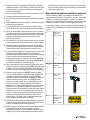 207
207
-
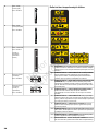 208
208
-
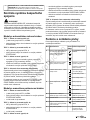 209
209
-
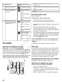 210
210
-
 211
211
-
 212
212
-
 213
213
-
 214
214
-
 215
215
-
 216
216
-
 217
217
-
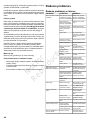 218
218
-
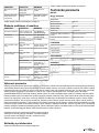 219
219
-
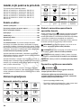 220
220
-
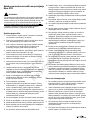 221
221
-
 222
222
-
 223
223
-
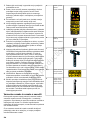 224
224
-
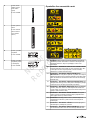 225
225
-
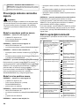 226
226
-
 227
227
-
 228
228
-
 229
229
-
 230
230
-
 231
231
-
 232
232
-
 233
233
-
 234
234
-
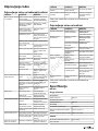 235
235
-
 236
236
-
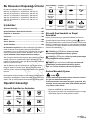 237
237
-
 238
238
-
 239
239
-
 240
240
-
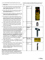 241
241
-
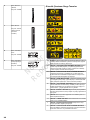 242
242
-
 243
243
-
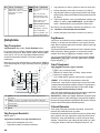 244
244
-
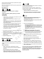 245
245
-
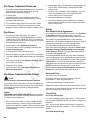 246
246
-
 247
247
-
 248
248
-
 249
249
-
 250
250
-
 251
251
-
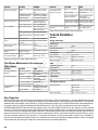 252
252
-
 253
253
-
 254
254
-
 255
255
-
 256
256


Simplicity 2691391-01 Kullanım kılavuzu
- Kategori
- Çim biçme makinaları
- Tip
- Kullanım kılavuzu
- Bu kılavuz aynı zamanda aşağıdakiler için de uygundur:
diğer dillerde
İlgili makaleler
-
Simplicity TRACTOR, EURO, RDLT Kullanım kılavuzu
-
-
Simplicity RIDER, SPX, SNAPPER Kullanım kılavuzu
-
Briggs & Stratton 2691264-00 Kullanım kılavuzu
-
Briggs & Stratton 2691266-00 Kullanım kılavuzu
-
-
-
-
-
Simplicity 2691070 Kullanım kılavuzu