Nilfisk-Euroclean CS7000 Instructions For Use Manual
- Tip
- Instructions For Use Manual


A-2 / ENGLISH
A-2 - FORM NO. 56041980 - CS7000
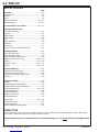
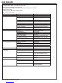
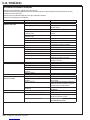
TABLE OF CONTENTS
Page
Introduction ................................................................................... A-2
Parts and Service ........................................................................... A-3
Nameplate ...................................................................................... A-3
Delivery ........................................................................................... A-3
Cautions and Warnings .........................................................A-4 – A-5
General Information ...............................................................A-6 – A-7
Know Your Machine / Control Panel ................................ A-8 – A-12
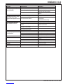
Preparing the Machine for Use
Pre-Operational Checklist ............................................................. A-13
Engine Oil ................................................................................... A-14
Engine Coolant ........................................................................... A-14
Engine Air Filter .......................................................................... A-15
Fuel ............................................................................................. A-15
Battery Installation ...................................................................... A-16
Main Broom .................................................................................. A-17
Scrub Brushes .............................................................................. A-17
Filling the Solution Tank & DustGuard™ Tank .............................. A-18
Operating the Machine ............................................................... A-19
Starting the Diesel Engine ............................................................ A-19
Starting the Propane Engine ........................................................ A-19
Starting the Gasoline / Petrol Engine ........................................... A-19
Detergent System (EcoFlex™ only) ..................................A-20 – A-21
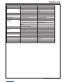
Sweeping ...........................................................................A-22 – A-23
Emptying the Hopper .........................................................A-22 – A-23
Scrubbing ..........................................................................A-24 – A-25
After Using the Machine ............................................................ A-26
Shutting Down the Diesel Engine ................................................. A-26
Shutting Down the Propane Engine ............................................. A-26
Shutting Down the Gasoline / Petrol Engine ................................ A-26
Hydraulic Oil ................................................................................. A-26
Maintenance Schedule ............................................................... A-27
Lubrication .................................................................................... A-28
Charging the Battery (Battery Models) ......................................... A-29
Charging the Battery Pack (Hybrid Models) ................................. A-30
Main Broom Maintenance ..................................................A-31 – A-32
Side Broom Maintenance ............................................................. A-33
Squeegee Maintenance ................................................................ A-34
Hopper Dust Control Filter ............................................................ A-35
Side Skirt Maintenance ................................................................. A-36
Troubleshooting .................................................................A-37 – A-39
Circuit Breaker Location ............................................................... A-37
Technical Specifi cations ............................................................... A-40
Material Composition and Recyclability ........................................ A-41
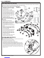
INTRODUCTION
This manual will help you get the most from your Nilfi sk™ Sweeper / Scrubber. Read it thoroughly before operating the machine. References to
“right” and “left” in this manual mean right or left as seen from the driver’s seat.
Note: Bold numbers or letters in parentheses indicate an item illustrated on pages A-8 – A-12 unless referred to a specifi c fi gure number.
revised 8/13

ENGLISH / A-3
FORM NO. 56041980 - CS7000 - A-3
PARTS AND SERVICE
Repairs, when required, should be performed by your Authorized Nilfi sk Service Center, who employs factory trained service personnel, and
maintains an inventory of Nilfi sk original replacement parts and accessories.
Call the Nilfi sk Authorized Service named below for repairs or service. Please specify the Model and Serial Number when discussing your
machine.
(Dealer, affi x service sticker here.)
NAMEPLATE
The Model Number and Serial Number of your machine are shown on the Nameplate. One nameplate is located on the wall of the operator’s
compartment just below the circuit breaker decal. The second nameplate is located on the chassis beneath the recovery tank. This information is
needed when ordering repair parts for the machine. Use the space below to note the Model Number and Serial Number of your machine for future
reference.
MODEL ________________________________________________
SERIAL NUMBER ________________________________________
DATE CODE ____________________________________________
Note: Reference the separately supplied engine manufacture’s maintenance and operator manual for more detailed engine specifi cation and
service data.
UN-CRATING
Upon delivery, carefully inspect the shipping crate and the machine for damage. If damage is evident, save all parts of the shipping crate so that
they can be inspected by the trucking company that delivered the machine. Contact the trucking company immediately to fi le a freight damage
claim.
1 After removing the crate, remove the wooden blocks next to the wheels.
2 Check the engine oil and coolant levels.
3 Check the hydraulic oil level.
4 Read the instructions in the Preparing the Machine For Use section of this manual, then fi ll the fuel tank.
5 Place a ramp next to the front end of the pallet.
6 Read the instructions in the Operating Controls and Operating the Machine sections of this manual and start the engine. Slowly drive the
machine forward down the ramp to the fl oor. Keep your foot lightly on the brake pedal until the machine is off the pallet.
CAUTION!
• Use extreme CAUTION when operating this machine. Be certain that you are thoroughly familiar with all operating instructions
before using this machine. If you have any questions, contact your supervisor or your local Nilfi sk Industrial Dealer.
• If the machine malfunctions, do not try to correct the problem unless your supervisor directs you to do so. Have a qualifi ed
company mechanic or an authorized Nilfi sk Dealer service person make any necessary corrections to the equipment.
• Use extreme care when working on this machine. Loose clothing, long hair, and jewelry can get caught in moving parts. Turn the
Key Ignition Switch OFF and remove the key before servicing the machine. Apply the parking brake before getting off of the machine.
Use good common sense, practice good safety habits and pay attention to the yellow decals on this machine.
• Drive the machine slowly on inclines. Use the Brake Pedal (38) to control machine speed while descending inclines. DO NOT turn
the machine on an incline; drive straight up or down.
• The maximum rated incline for sweeping and scrubbing is 10°. The maximum rated incline during transport is 10°.
MODIFICATIONS
Modifi cations and additions to the cleaning machine which affect capacity and safe operation shall not be performed by the customer or user
without prior written approval from Nilfi sk-Advance Inc. Unapproved modifi cations will void the machine warranty and make the customer liable for
any resulting accidents.

A-4 / ENGLISH
A-4 - FORM NO. 56041980 - CS7000
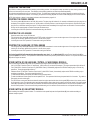
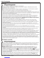
CAUTIONS AND WARNINGS
Nilfi sk uses the symbols below to signal potentially dangerous conditions. Always read this information carefully and take
the necessary steps to protect personnel and property.
DANGER!
Is used to warn of immediate hazards that will cause severe personal injury or death.
WARNING!
Is used to call attention to a situation that could cause severe personal injury.
CAUTION!
Is used to call attention to a situation that could cause minor personal injury or damage to the machine or other property.
Read all instructions before using.
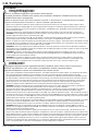
GENERAL SAFETY INSTRUCTIONS
Specifi c Cautions and Warnings are included to warn you of potential danger of machine damage or bodily harm.
This machine is only suitable for commercial use, for example at manufacturing plants, warehouses, cement block & brick facilities,
parking garages, municipal parks, entertainment and transportation facilities.
DANGER!
• This machine emits exhaust gases (carbon monoxide) that can cause serious injury or death, always provide
adequate ventilation when using machine. (Diesel & LPG models only.)
WARNING!
• This machine shall be used only by properly trained and authorized persons.
• This machine is not intended for use by persons (including children) with reduced physical, sensory or mental
capabilities, or lack of experience and knowledge.
• While on ramps or inclines, avoid sudden stops. Avoid abrupt sharp turns. Use low speed down ramps.
• To avoid hydraulic oil injection or injury, always wear appropriate clothing and eye protection when working with or
near hydraulic system.
• Keep sparks, fl ame and smoking materials away from battery. Explosive gases are vented during normal operation.
• Charging the battery produces highly explosive hydrogen gas. Charge battery only in well-ventilated areas away
from open fl ame. Do not smoke while charging the battery.
• Remove all jewelry when working near electrical components.
• Turn the key switch off (O) and disconnect the batteries before servicing electrical components.
• Never work under a machine without safety blocks or stands to support the machine.
• Do not dispense fl ammable cleaning agents, operate the machine on or near these agents, or operate in areas where
fl ammable liquids exist.
• Do not pressure wash operator control panel, fuse panel, contactor panel or engine compartment area.
• Do not inhale exhaust gas fumes. Only use indoors when adequate ventilation is provided, and when a second person
has been instructed to look after you.
• Do not use the machine without a falling object protective structure (FOPS) in areas where it is likely that the operator
is hit by falling objects.
• Machines shall be parked safely.
• The machine shall be inspected by a qualifi ed person regularly, in particular regarding the LPG container and their
connections, as required for safe operation by regional or national regulations.
• Observe the Gross Vehicle Weight, GVW, of the machine when loading, driving, lifting or supporting the machine.
revised 2/13

ENGLISH / A-5
FORM NO. 56041980 - CS7000 - A-5
CAUTION!
• This machine is not approved for use on public paths or roads.
• This machine is not suitable for picking up hazardous dust.
• Use care when using scarifi er discs and grinding stones. Nilfi sk will not be held responsible for any damage to fl oor
surfaces caused by scarifi ers or grinding stones.
• When operating this machine, ensure that third parties, particularly children, are not endangered.
• Before performing any service function, carefully read all instructions pertaining to that function.
• Do not leave the machine unattended without fi rst turning the key switch off (O), removing the key and applying the
parking brake.
• Turn the key switch off (O) before changing the brushes, and before opening any access panels.
• Take precautions to prevent hair, jewelry, or loose clothing from becoming caught in moving parts.
• Use caution when moving this machine in below freezing temperature conditions. Any water in the solution or recovery
tanks or in the hose lines could freeze.
• The battery must be removed from the machine before the machine is scrapped. The disposal of the battery should
be safely done in accordance with your local environmental regulations.
• Do not use on surfaces having a gradient exceeding that marked on the machine.
• Before use, all doors and hoods should be properly latched.
SAVE THESE INSTRUCTIONS

A-6 / ENGLISH
A-6 - FORM NO. 56041980 - CS7000
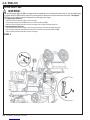
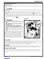
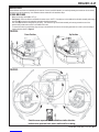
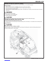
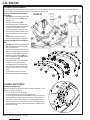
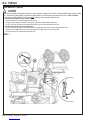
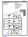
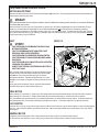
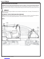
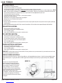
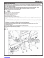
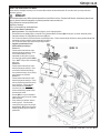
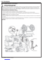
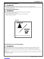
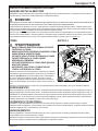
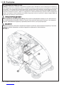
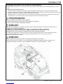
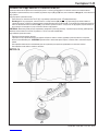
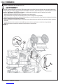
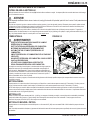
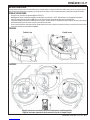
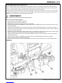
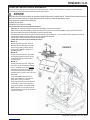
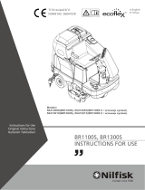
HOPPER SAFETY BAR
WARNING!
Make sure the Hopper Safety Bar (23) is engaged whenever attempting to do any maintenance work under or near the raised hopper.
The Hopper Safety Bar (23) holds the hopper in the raised position to allow work to be performed under the hopper. See Figure 1.
NEVER rely on the machine’s hydraulic components to safely support the hopper.
A - To Engage Hopper Safety Bar:
1. Press and hold the hopper raise switch to raise the hopper.
2. Pull the hopper safety bar handle (21) toward you to retract the safety bar (23).
3. Press and hold the hopper lower switch to lower the hopper until it contacts the hopper safety bar.
B - To Disengage Hopper Safety Bar:
1. Press and hold the hopper raise switch to raise the hopper slightly so it lifts off of the hopper safety bar.
2. Push the hopper safety bar handle (21) toward the front of the machine to extend the safety bar (23).
3. Press and hold the hopper lower switch to lower the hopper.
FIGURE 1

ENGLISH / A-7
FORM NO. 56041980 - CS7000 - A-7
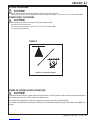
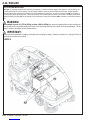
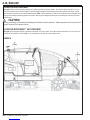
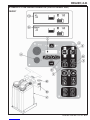
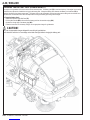
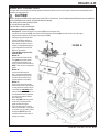
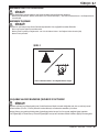
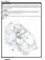
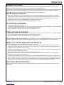
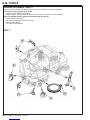
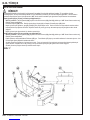
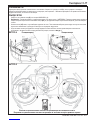
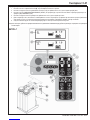
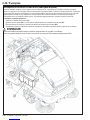
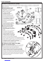
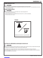
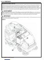
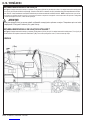
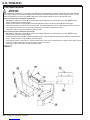
FIGURE 2
TOWING OR PUSHING A DISABLED MACHINE
CAUTION!
If the machine must be towed or pushed, make sure the Key Switch is in the Off position and do not move the machine faster than a
normal walking pace (2-3 mph, 3-5 kph) and for short distances only.
A second option which will allow for steering while pushing or towing the machine is to do the following:
-Turn the Key Switch (A) ON while pressing and holding both the Speed Switch (K) and the High Pressure Wash Switch (N) for two
seconds.
JACKING THE MACHINE
CAUTION!
Never work under a machine without safety stands or blocks to support the machine.
• When jacking the machine, do so at designated locations (Do Not jack on the hopper) - see Jack Point / Tie Down Point locations (33).
TRANSPORTING THE MACHINE
CAUTION!
Before transporting the machine on an open truck or trailer, make sure that . . .
• All access doors are latched securely.
• The machine is tied down securely - see Jack Point / Tie Down Point locations (33).
• The machine parking brake is set.
Jack Point / Tie Down Point symbol

A-8 / ENGLISH
A-8 - FORM NO. 56041980 - CS7000
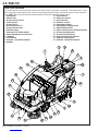
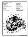
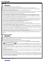
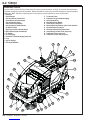
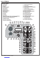
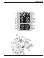
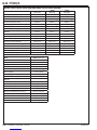
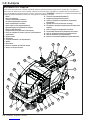
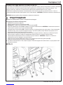
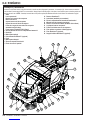
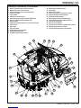
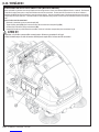
KNOW YOUR MACHINE
As you read this manual, you will occasionally run across a bold number or letter in parentheses - example: (2). These numbers refer to an item
shown on these pages unless otherwise noted. Refer back to these pages whenever necessary to pinpoint the location of an item mentioned in
the text. NOTE: Refer to the service manual for detailed explanations of each item illustrated on the next 5 pages.
1 Steering Wheel
2 Operator’s Seat
3 Recovery Tank Tip-Out Lock
4 Solution Tank Fill
5 Recovery Tank Lid
6 Vacuum Filter Access Lid
7 Recovery Tank Drain Hose
8 Left Skirt Assembly
9 Exhaust Pipe (LPG & Diesel models)
10 Engine Compartment Access Panel Latch
11 Front Wheel
12 Left Side Broom
13 DustGuard™ Spray Nozzles (optional)
14 Headlights
15 Right Side Broom
16 Hopper Cover Latches
17 Dust Control Filter
18 DustGuard™Tank Fill
19 Battery (battery models)
20 Engine/Battery Compartment Latch
21 Hopper Safety Bar Handle
22 Engine Coolant Reservoir (LPG & Diesel models)
51 Recovery Tank Debris Basket
52 Recovery Tank Shutoff Floats
54 High Pressure Wash Filter (optional)
55 DustGuard™Filter (optional)
56 DustGuard™Shut-Off Valve (optional)
54
123456
7
8
9
10
11
12
14
15
16
18
20 21
13
17
19
22
51
52
56
55

ENGLISH / A-9
FORM NO. 56041980 - CS7000 - A-9
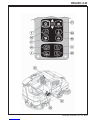
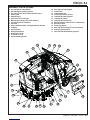
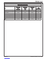
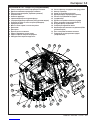
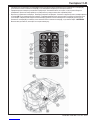
KNOW YOUR MACHINE (CONTINUED)
24 Recovery Tank Lid Latch
25 Recovery Tank Tip-Out Grip
26 Circuit Breaker Panel (see troubleshooting)
27 Control Panel
28 Radiator Cap
29 Air Filter Service Indicator
30 Engine Starting Battery (LPG & Diesel models)
31 LPG Fuel Tank (LPG models)
32 Battery Pack
33 Jack Point / Tie Down Point Location
34 Lower Cover
35 Right Side Door
36 Broom Access Door
37 Drive Pedal, Directional/Speed
38 Brake Pedal/Parking Brake
39 Right Scrub Skirt Assy
40 Edge Guard Retainer Knob
41 Solution Filter
42 Solution Shut-Off Valve
43 Solution Tank Drain Hose
44 Squeegee Removal Knobs
45 Squeegee Assembly
46 Squeegee Tilt Adjustment Handle
47 Detergent Cartridges (EcoFlex™ models only)
48 Engine Air Filter
49 Hydraulic Oil Reservoir
50 Engine Oil Dipstick (LPG & Diesel models)
53 Steering Wheel Tilt Adjust Lever
57 Rear Squeegee Guard (optional)
24
25
26 27 28 29
30
31
32
33
34
35
36
37
38
39
40
41
42
43
44 45
46
33
47
50 48
49
53
57

A-10 / ENGLISH
A-10 - FORM NO. 56041980 - CS7000
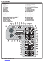
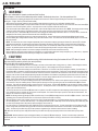
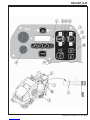
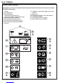
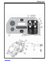
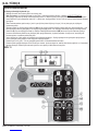
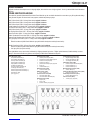
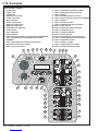
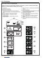
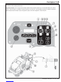
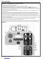
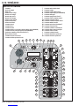
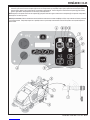
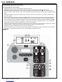
CONTROL PANEL
A Key Switch
B Emergency Stop
C LCD Display
D Left Turn Indicator
E Left Turn Signal
F Hazard Flasher
G Right Turn Signal
H Right Turn Indicator
I Attention Indicator
J Warning Indicator
K Speed Switch
L Headlight Switch
M Horn Switch
N High-Pressure Wash Switch (optional see IS56090038)
O Extended Scrub Switch (optional see IS56090061)
P Burst of Power Switch (EcoFlex™ only)
Q Scrub Pressure Increase
R One-Touch™ Scrub Switch
S Scrub Pressure Decrease Switch
T Solution Flow Increase Switch
U Solution Switch
V Solution Flow Decrease Switch
W Vacuum/Wand Switch (see IS56090054)
X Detergent Switch
Y One-Touch™ Sweep Switch
Z Broom Height Raise Switch
AA Broom Select Switch
BB Broom Height Lower Switch
CC Side Broom Switch
DD DustGuard™Spray Switch
EE Filter Shaker Switch
FF Dust Control Fan Switch
GG Main Broom Float Switch
HH Hopper Raise Switch
II Hopper Lower Switch
JJ Hopper Door Open Switch
KK Hopper Door Close Switch
A
B
I C D E F G H J
K L M
O
N
P
Q R S
T
U
V
W
X
Y
Z
AA
CC
BB
DD
EE
JJ
KK
GG
FF
HH
II

ENGLISH / A-11
FORM NO. 56041980 - CS7000 - A-11
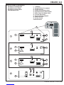
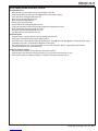
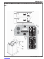
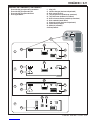
CONTROL PANEL (CONTINUED)
1 Main Display Screen Battery Model
2 Main Display Screen LPG Model
3 Main Display Screen Diesel Model
4 Broom Adjustment Screen
C LCD Display
C1 Detergent Indicator (if so equipped)
C2 Solution Tank Level
C3 Sweep/Scrub Time (Battery models)
C4 Engine Run Time (LPG & Diesel models)
C5 Battery Charge Level (Battery models)
C6 Fuel Level (Diesel model)
C7 Recycle System (if so equipped)
C8 Main Broom Position
C9 Broom(s) Selected
C10 Broom Direction
1
C1
2
3
C1
C1
C7
C8
C3
C4
C4
C5
C6
C
4
C2
C2
C2
C9 C10
C7

A-12 / ENGLISH
A-12 - FORM NO. 56041980 - CS7000
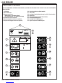
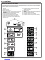
CONTROL PANEL (CONTINUED)
IF ANY OF THE WARNING / ATTENTION ICONS MARKED (X) BELOW ARE DISPLAYED PLEASE CONTACT YOUR NILFISK AUTHORIZED
SERVICE CENTER.
C LCD Display
C11 Non-Critical Fault
C12 Battery Low Indicator
(Battery models = low battery voltage)
(LPG & Diesel models = low battery pack voltage)
C13 Solution Level Low Caution Icon
C14 Hopper Temperature Caution Icon (optional)
C15 Hopper Filter Plugged Caution Icon (optional)
C16 Glow Plug Caution Icon (Diesel models)
C17 Critical Fault
C18 Low Engine Starting Battery Warning Icon (LPG & Diesel models)
C19 Engine Fault
C20 Low Fuel Warning Icon (LPG & Diesel models)
C21 Parking Brake Warning Icon
C22 Recovery Tank Full Warning Icon
C23 Engine Temperature Hot Warning Icon
C11
C
X
1.0
C12
C13
C14
C15
C17
C19
C20
C21
C22
C23
X
X
X
X
C16
C18

ENGLISH / A-13
FORM NO. 56041980 - CS7000 - A-13
PRE-OPERATIONAL CHECKLIST
Before Each Use:
* Inspect the machine for damage, oil or coolant leaks.
* Squeeze the rubber dust cup on the Engine Air Filter (48) to release built-up dust.
* Check the Air Filter Service Indicator (29).
* Check the engine coolant level (22).
* Check the engine oil level (50).
* Check the hydraulic oil level.
* Check the Fuel Gauge (C6) on the diesel models.
* Check the Fuel Gauge located on the LPG tank (31) for propane model.
* Check the Battery Charge Level (C5) on battery models.
* Make sure the battery charger is not connected to the machine.
* Make sure the recovery tank is empty.
In the Driver’s Seat:
* Be sure that you understand the operating controls and their functions.
* Adjust the seat to allow easy reach of all controls.
* Insert the Master Key and turn the Ignition Key Switch (A) to the ON position. Check for proper operation of the Horn (M), Hour Meter (C3 or
C4) and Headlights (L). Turn the Ignition Key Switch (A) OFF.
* Check the Brake Pedal (38). The pedal should be fi rm and should not go all the way down. The latch should hold the pedal when applied.
(Report all defects immediately to service personnel).
Plan Your Cleaning in Advance:
* Arrange long runs with a minimum of stopping or starting.
* Allow 6 inches (15 cm) of broom path overlap to ensure complete coverage.
* Avoid making sharp turns, bumping into posts, or scraping the side of the machine.

A-14 / ENGLISH
A-14 - FORM NO. 56041980 - CS7000
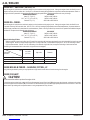
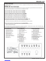
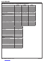
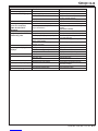
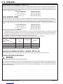
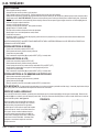
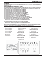
ENGINE OIL – GASOLINE / PETROL, LP
Check the engine oil level when the machine is parked on a level surface and the engine is cool. Change the engine oil after the fi rst 50 hours of
operation and every 200 hours after that. Use any SF or SG rated oil meeting API specifi cations and suited to seasonal temperatures. Refer to
the Engine Workshop manual for oil capacities and additional engine specifi cations. Replace the oil fi lter with every oil change.
TEMPERATURE RANGE OIL WEIGHT
Above 77 °F (25 °C) SAE 30 or SAE 10W-30
32 °F to 77 °F (0 °C to 25 °C) SAE 20 or SAE 10W-30
Below 32 °F (0 °C) SAE 10W or SAE 10W-30
ENGINE OIL - DIESEL
Check the engine oil level when the machine is parked on a level surface and the engine is cool. Change the engine oil after the fi rst 50 hours
of operation and every 200 hours after that. Use CF, CF-4 or CG-4 oil meeting API specifi cations and suited temperatures (*important reference
the oil/fuel type note below for further diesel oil recommendations). Refer to the Engine Workshop manual for oil capacities and additional engine
specifi cations. Replace the oil fi lter with every oil change.
TEMPERATURE RANGE OIL WEIGHT
Above 77 °F (25 °C) SAE 30 or SAE 10W-30
32 °F to 77 °F (0 °C to 25 °C) SAE 20 or SAE 10W-30
Below 32 °F (0 °C) SAE 10W or SAE 10W-30
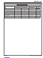
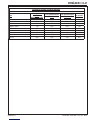
* Diesel Lubricating Oil Note:
With the emission control now in effect, the CF-4 and CG-4 lubricating oils have been developed for use with a low-sulfur fuel used in on-road
vehicle engines. When an off-road vehicle engine runs on a high-sulfur fuel, it is advisable to employ the CF, CD or CE lubricating oil with a
high total base number. If the CF-4 or CG-4 lubricating oil is used with a high-sulfur fuel, change the lubricating oil at shorter intervals.
• Lubricating oil recommended when a low-sulfur or high-sulfur fuel is employed.
Fuel
Lubricating
Oil class
Low sulfur
(0.5 % ≥)High sulfur Remarks
CF OO
TBN ≥ 10
CF-4 OX
CG-4 OX
O : Recommended X : Not recommended
ENGINE BREAK-IN PERIOD – GASOLINE / PETROL, LP
During initial engine break-in period you may experience a slight smell or small amount of smoke coming from the engine.
ENGINE COOLANT
CAUTION!
Do not remove the radiator cap when the engine is hot.
To check the engine coolant level, unlatch the Engine Compartment Access Panel Latch (10) and remove the side panel, and observe the coolant
level in the Engine Coolant Reservoir (22). If the level is low add automotive type anti-freeze appropriately diluted for the environment. Clean the
radiator exterior by washing with low-pressure water or using compressed air every 30 hours.
revised 8/13

ENGLISH / A-15
FORM NO. 56041980 - CS7000 - A-15
PRE-OPERATIONAL CHECKLIST
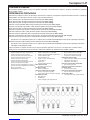
ENGINE AIR FILTER
Check the Air Filter Service Indicator (29) before each use of the machine. Do not service the air fi lter unless the red fl ag is visible in the service
indicator.
CAUTION!
When servicing the engine air fi lter elements, use extreme care to prevent loose dust from entering the engine. Dust can severely
damage the engine.
The engine air fi lter contains a Primary (outer) and a Safety (inner) fi lter element. The Primary Element may be cleaned twice before being
replaced. The Safety Element should be replaced every third time that the Primary Filter Element is replaced. Never attempt to clean the Inner
Safety Element.
To clean the Primary Filter Element, unsnap the 2 clips at the end of the air fi lter and remove the end housing. Pull the primary element out. Clean
the element with compressed air (maximum pressure 100 psi (6.89 bar)) or wash it with water (maximum pressure 40 psi (2.75 bar)). DO NOT put
the element back into the canister until it is completely dry.
P1
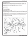
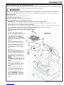
FUEL
WARNING!
• ALWAYS STOP THE ENGINE BEFORE FILLING THE FUEL
TANK.
• ALWAYS ROTATE THE DIESEL FUEL TANK OUTWARD
BEFORE REFUELING.
• DO NOT SMOKE WHILE FILLING THE FUEL TANK.
• FILL THE FUEL TANK IN A WELL-VENTILATED AREA.
• DO NOT FILL THE FUEL TANK NEAR SPARKS OR OPEN
FLAME.
• USE ONLY THE FUEL SPECIFIED ON THE FUEL TANK
DECAL.
On machines with diesel and gasoline / petrol engines, a decal near the
fuel tank fi ller neck shows the proper fuel to use in the machine. See
Figure 2.5. Pull out quick release Pin (P1) then rotate the fuel tank.
Before removing the cap from the tank, wipe all dust and dirt from the cap
and from the top of the tank to keep the fuel as clean as possible.
On machines with propane engines, a decal near the tank gives specifi c
information about the proper type of tank to be used on the machine.
DIESEL ENGINE
Fill the tank with Number 2 Diesel Fuel if the machine will be used in an area where the temperature is 30° Fahrenheit (0° Celsius) or higher. Use
Number 1 Diesel Fuel if the machine will be used in an area where the temperature is below 30° Fahrenheit (0° Celsius).
NOTE: If the diesel machine runs out of fuel completely, the fuel system must be bled before the engine can be re-started. To avoid this situation,
fi ll the fuel tank when the fuel gauge indicates 1/4 tank. Fuel tank capacity is 10.25 gallons (38.8 liters).
LPG ENGINE
Mount a standard 33 lb. (14.85 kg) liquid withdrawal propane tank on the machine, connect the fuel hose and open the shutoff valve on the tank.
Wear gloves when connecting or disconnecting the fuel hose. Shut the propane tank service valve OFF when the machine is not in use.
GASOLINE / PETROL ENGINE
Fill the tank with unleaded (AKI) 87 octane regular gasoline/petrol that is the average of the RON + MON indicated on pumps as (R+M)/2.
Note: Reference the separately supplied engine manufacture’s maintenance and operator manuals for more detailed engine specifi cation and
service data.
FIGURE 2.5
revised 8/13

A-16 / ENGLISH
A-16 - FORM NO. 56041980 - CS7000
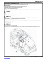
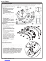
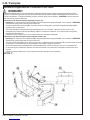
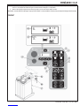
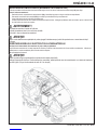
BATTERY INSTALLATION
See Figure 3. The battery required for this machine is sold separately. The maximum battery weight for this machine is 1,875 lbs (850 kg); the
minimum battery weight is 1,400 lbs (635kg). For proper battery installation, please consult your Nilfi sk Industrial Dealer. DO NOT attempt to
install the battery with an overhead hoist or forklift; it can only be installed with a battery cart. Connect the connector plug (AB) on the battery to
the machine plug behind the steering wheel. Make sure the battery is fi rmly seated against the brace on the left side of the battery compartment.
Reinstall the battery Stop Plate (AC) on the right side of the compartment and snug up the Bumpers (AD) so the battery cannot slide from side-to-
side.
WARNING!
Battery weight in excess of 1,875 lbs (850 kg) or below 1,400 lbs (635kg) may cause the premature failure of parts including the
tires, and may result in decreased stability and control, which could cause personal injury or death and/or property damage. Use of a
battery in excess of the weight limit will void the warranty.
IMPORTANT!
Follow instructions packed with the battery and charger before charging the battery. Read the instructions for Charging the Battery in
the Maintenance section of this manual.
FIGURE 3

ENGLISH / A-17
FORM NO. 56041980 - CS7000 - A-17
MAIN BROOM
Several different main brooms are available for this machine. Contact your Nilfi sk dealer if you need help selecting the best broom for the surface
and litter that you will be sweeping. Note: Reference broom maintenance for installation steps.
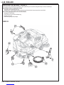
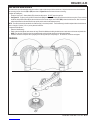
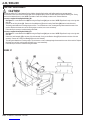
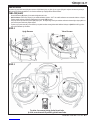
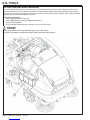
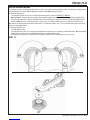
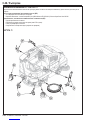
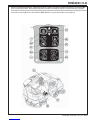
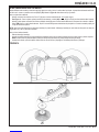
SCRUB BRUSHES
1 Make sure the Key Switch (B) is OFF (O).
2 See Figure 4. Raise the side skirt assemblies for easier access. NOTE: Lift straight up on the middle of the side skirt assembly and engage
the catch (AE) to keep the skirt assembly raised while installing the brushes.
3 Pull Lever (AF) outward to disengage the gas spring. This allows the right scrub brush assembly to be swung towards the rear of the
machine and provide easier access to the middle scrub brush.
4 To mount the brushes (or pad holders) align the lugs on the brush with the holes on the mounting plate and turn to lock in place according to
rotation directions shown in Figure 5.
FIGURE 4 Down Position Up Position
Outside arrows represent brush installation rotation direction.
Inside arrows represent brush motor rotation while scrubbing.
FIGURE 5

A-18 / ENGLISH
A-18 - FORM NO. 56041980 - CS7000
FILLING THE SOLUTION TANK
See Figure 6. Fill the solution tank with a maximum of 75 gallons (284 Liters) of cleaning solution. Do not fi ll the solution tank above 7.5 cm (3
inches) from the bottom of the Solution Fill (4). The solution should be a mixture of water and the proper cleaning chemical for the job. Always
follow the dilution instructions on the chemical container label. NOTE: EcoFlex machines can either be used conventionally with detergent mixed
in the tank or the detergent dispensing system can be used. When using the detergent dispensing do not mix detergent in the tank, plain water
should be used.
CAUTION!
Use only low-foaming, non-fl ammable liquid detergents intended for machine application. Water temperature should not exceed 130
degrees Fahrenheit (54.4 degrees Celsius).
FILLING THE DUSTGUARD™ SOLUTION TANK
See Figure 6. Fill the solution tank with a maximum of 29 gallons (110 Liters) of water. Do not fi ll the solution tank above 7.5 cm (3 inches) from
the bottom of the DustGuard™ Tank Fill (18). Do not mix detergent in the tank, plain water should be used.
FIGURE 6

ENGLISH / A-19
FORM NO. 56041980 - CS7000 - A-19
OPERATING THE MACHINE
The CS7000 is a rider-type automatic fl oor sweeping and scrubbing machine. It is designed to sweep up debris, lay down cleaning solution, scrub
the fl oor, and vacuum dry all in one pass. The sweeping and scrubbing operations can also be performed separately.
The controls were designed with one touch operation in mind. For single pass scrubbing the user can simply depress one switch and all scrub
functions on the machine will be enabled. For sweeping, the operator can simply depress one switch and all sweeping functions will be enabled.
NOTE: Bold numbers or letters in parentheses indicate an item illustrated on pages 8-12.
STARTING THE DIESEL ENGINE
1 Turn the key switch (A) clockwise to the RUN (ON) position. The glow plugs will activate for 10 seconds as indicated by the glow plug icon on
the display. If the engine is already warm, turn the key switch to the start position to crank the engine. If the engine is cold, wait for the glow
plug icon to turn off before cranking the engine. The engine should start immediately. If the engine does not start within 15 seconds release
the key, wait for approximately one minute and repeat the above steps.
2 Let the engine run at IDLE speed for fi ve minutes before using the machine.
STARTING THE LPG ENGINE
1 Open the service valve on the LPG fuel tank.
2 Turn the Ignition Key Switch (A) clockwise to the START position and release it as soon as the engine starts. If the engine does not start after
cranking for 15 seconds, release the key, wait for 1 minute, then try again.
3 Let the engine run at “IDLE” speed for 5 minutes before using the machine.
STARTING THE GASOLINE / PETROL ENGINE
1 Turn the Ignition Key Switch (A) clockwise to the START position and release it as soon as the engine starts. If the engine does not start after
cranking for 15 seconds, release the key, wait for 1 minute, then try again.
2 Let the engine run at “IDLE” speed for 5 minutes before using the machine.
The Engine Speed (RPM) will automatically adjust depending upon load. Use the Drive Pedal (37) not the Engine Speed Switch (K) to
control the speed of the machine. The speed of the machine will increase as the pedal is pushed closer to the fl oor. Do not press the Drive Pedal
(37) until the engine has started.
SPEED SWITCH (K) ON GASOLINE / PETROL, LP AND DIESEL MODELS:
There are three engine speed settings that can be selected by the engine speed switch (K) on the control panel.
1 “Idle” (1700 RPM – Gasoline / Petrol, LP and Diesel). Use for warm up, cool down and transport. The engine speed switch light will be off.
2 “Run” (2500 RPM – Gasoline / Petrol and LP) (2200 RPM - Diesel). Automatically adjusts to this RPM for sweeping only or vacuum only
operations. The engine speed light will be on.
3 “Maximum Power” (2700 RPM – Gasoline / Petrol and LP) (2400 RPM - Diesel). Automatically adjusts to this RPM for scrubbing only or
scrubbing and sweeping. The engine speed light will be on.
4 To select between Idle and Run press and release the engine speed switch.
5 To select the Maximum Power speed, fi rst set the speed to Run. Then press and hold the engine speed switch for 2 seconds. To go back to
Run speed, press the switch again.
6 The CS7000 has an automatic idle feature that will reduce the engine speed to idle when the foot pedal (37) has been in the neutral position
for 20 seconds or more. The selected engine speed will automatically resume when the foot pedal is moved from neutral. If the engine speed
switch (K) is pressed while in idle-override, the automatic idle feature will be temporarily disabled until the next time the foot pedal is moved
from the neutral position. This can be useful during troubleshooting or if it is desired to let the machine run at full speed for warming up.
SPEED SWITCH (K) ON BATTERY MODELS:
While scrubbing the maximum speed is limited. To override the scrub speed limit press the Speed Switch (K), this enables scrubbing at
maximum transport speed.
revised 4/13

A-20 / ENGLISH
A-20 - FORM NO. 56041980 - CS7000
DETERGENT SYSTEM PREPARATION AND USE (ECOFLEX MODELS ONLY)
The Detergent Cartridges (47) are located below the Operator’s Seat (2). Fill the detergent cartridge with a maximum of 2.2 gallons (8.32 Liters) of
detergent. SERVICE NOTE: Remove the detergent cartridge from the detergent box prior to fi lling to avoid spilling detergent on the machine.
It is recommended that a separate cartridge be used for each detergent you plan to use. The detergent cartridges have a white decal on them so
you can write the detergent name on each cartridge to avoid mixing them up. When installing a new cartridge, remove the Cap (BC) and place the
cartridge in the detergent box. Install the Dry Break Cap (BD) as shown.
The system should be purged of previous detergent when switching to a different detergent. SERVICE NOTE: Move machine over fl oor drain
before purging because a small amount of detergent will be dispensed in the process.
To Purge When Changing Chemicals (SCRUB AND SOLUTION SYSTEMS MUST BE OFF):
1 Disconnect and remove the detergent cartridge.
2 Turn the key switch (A) to the RUN (ON) position. Wait a few seconds for the start-up sequence to fi nish.
3 Press and hold the Detergent Switch (X) and the Solution Switch (U) for approximately 2 seconds. Release the switch when the chemical
purge icon (C12) appears on the display and the indicator on the detergent switch (X) starts fl ashing. NOTE: Once activated the purge
process takes at least 20 seconds. See illustration on next page for Detergent System indicators. Normally one purge cycle is adequate to
purge the system.
To Purge Weekly (SCRUB AND SOLUTION SYSTEMS MUST BE OFF):
1 Disconnect and remove the detergent cartridge. Install and connect a Cartridge fi lled with clean warm water.
2 Turn the key switch (A) to the RUN (ON) position. Wait a few seconds for the start-up sequence to fi nish.
3 Press and hold the Detergent Switch (X) and the Solution Switch (U) for approximately 2 seconds. Release the switch when the chemical
purge icon (C12) appears on the display and the indicator on the detergent switch (X) starts fl ashing. NOTE: Once activated the purge
process takes at least 20 seconds. See illustration on next page for Detergent System indicators. Normally one purge cycle is adequate to
purge the system.
When the detergent level is nearing the bottom of the cartridge it is time to refi ll or replace the cartridge(s).
Detergent Percentage (SCRUB SYSTEM MUST BE ON):
No detergent is dispensed until the scrub and detergent systems are activated and the Drive Pedal (37) pushed forward.
The detergent mixture icon (C1) will always be displayed when the detergent system is on.
There are 4 modes of EcoFlex operation:
1. Minimum Concentration Detergent – Burst of Power Indicator (P1) ON (Activated by momentarily pressing Burst of Power switch when in
maximum concentration detergent mode). See below the steps “To program the Minimum Concentration Detergent Level”.
2. Maximum Concentration Detergent – Burst of Power Indicator (P1) OFF (Activated by pressing and holding Burst of Power switch for two
seconds). See below the steps “To program the Maximum Concentration Detergent Level”. Do not use a concentration level exceeding the
detergent manufacturer’s recommendation.
3. Burst of Power – Press the Burst of Power Switch (P) to increase the detergent percentage for one minute to the pre-programmed “maximum”
level of concentration (as noted in programming instructions below). This will also cause the solution fl ow rate to increase to the next level
and the scrub pressure to increase to the next level. Burst of Power Indicator (P1) will blink for one minute.
4. Plain Water - During scrubbing, the detergent system can be turned off at any time by pressing the Detergent ON/OFF Switch (X) to
allow scrubbing with water only. Detergent Indicator (X1) will be OFF.
To program the Minimum Concentration detergent level
Press the OneTouch™ Scrub switch 1. (R) to activate the scrub system.
Ensure the Burst of Power Indicator 2. (P1) is ON (minimum concentration detergent mode).
Press the Detergent ON/OFF Switch 3. (X) to turn off the detergent system (detergent indicator (X1) OFF).
Press and hold the detergent switch for approximately 2 seconds until the indicator fl ashes.4.
While the indicator is fl ashing, pressing and releasing the detergent switch will cycle through the available percentages (0.25%, 0.3%, 0.4%, 5.
0.5%, 0.7%, 0.8%, 1%, 1.5%, 2%, 3%, 3.8%).
Once the desired percentage is displayed on the screen 6. (C1), stop and it will save the setting after 3 seconds.
Whenever the minimum concentration setting is set to a higher concentration than the current maximum programmed concentration setting. 7.
The maximum concentration default setting will be equal to the minimum concentration setting until changed by the operator.
To program the Maximum Concentration detergent level
Press the OneTouch™ Scrub switch 1. (R) to activate the scrub system.
Press and hold the Burst of Power Switch 2. (P) for approximately 2 seconds until the indicator (P1) is OFF (maximum concentration detergent
mode).
Press the Detergent ON/OFF Switch 3. (X) to turn off the detergent system (detergent indicator (X1) OFF).
Press and hold the detergent switch for approximately 2 seconds until the indicator fl ashes.4.
While the indicator is fl ashing, pressing and releasing the detergent switch will cycle through the available percentages (Note: only percentages 5.
that are a higher concentration or equal to the minimum detergent setting will be available.
Once the desired percentage is displayed on the screen 6. (C1), stop and it will save the setting after 3 seconds.
Once set, the detergent fl ow rate automatically increases and decreases with the solution fl ow rate, but the detergent percentage remains the
same.
Sayfa yükleniyor...
Sayfa yükleniyor...
Sayfa yükleniyor...
Sayfa yükleniyor...
Sayfa yükleniyor...
Sayfa yükleniyor...
Sayfa yükleniyor...
Sayfa yükleniyor...
Sayfa yükleniyor...
Sayfa yükleniyor...
Sayfa yükleniyor...
Sayfa yükleniyor...
Sayfa yükleniyor...
Sayfa yükleniyor...
Sayfa yükleniyor...
Sayfa yükleniyor...
Sayfa yükleniyor...
Sayfa yükleniyor...
Sayfa yükleniyor...
Sayfa yükleniyor...
Sayfa yükleniyor...
Sayfa yükleniyor...
Sayfa yükleniyor...
Sayfa yükleniyor...
Sayfa yükleniyor...
Sayfa yükleniyor...
Sayfa yükleniyor...
Sayfa yükleniyor...
Sayfa yükleniyor...
Sayfa yükleniyor...
Sayfa yükleniyor...
Sayfa yükleniyor...
Sayfa yükleniyor...
Sayfa yükleniyor...
Sayfa yükleniyor...
Sayfa yükleniyor...
Sayfa yükleniyor...
Sayfa yükleniyor...
Sayfa yükleniyor...
Sayfa yükleniyor...
Sayfa yükleniyor...
Sayfa yükleniyor...
Sayfa yükleniyor...
Sayfa yükleniyor...
Sayfa yükleniyor...
Sayfa yükleniyor...
Sayfa yükleniyor...
Sayfa yükleniyor...
Sayfa yükleniyor...
Sayfa yükleniyor...
Sayfa yükleniyor...
Sayfa yükleniyor...
Sayfa yükleniyor...
Sayfa yükleniyor...
Sayfa yükleniyor...
Sayfa yükleniyor...
Sayfa yükleniyor...
Sayfa yükleniyor...
Sayfa yükleniyor...
Sayfa yükleniyor...
Sayfa yükleniyor...
Sayfa yükleniyor...
Sayfa yükleniyor...
Sayfa yükleniyor...
Sayfa yükleniyor...
Sayfa yükleniyor...
Sayfa yükleniyor...
Sayfa yükleniyor...
Sayfa yükleniyor...
Sayfa yükleniyor...
Sayfa yükleniyor...
Sayfa yükleniyor...
Sayfa yükleniyor...
Sayfa yükleniyor...
Sayfa yükleniyor...
Sayfa yükleniyor...
Sayfa yükleniyor...
Sayfa yükleniyor...
Sayfa yükleniyor...
Sayfa yükleniyor...
Sayfa yükleniyor...
Sayfa yükleniyor...
Sayfa yükleniyor...
Sayfa yükleniyor...
Sayfa yükleniyor...
Sayfa yükleniyor...
Sayfa yükleniyor...
Sayfa yükleniyor...
Sayfa yükleniyor...
Sayfa yükleniyor...
Sayfa yükleniyor...
Sayfa yükleniyor...
Sayfa yükleniyor...
Sayfa yükleniyor...
Sayfa yükleniyor...
Sayfa yükleniyor...
Sayfa yükleniyor...
Sayfa yükleniyor...
Sayfa yükleniyor...
Sayfa yükleniyor...
Sayfa yükleniyor...
Sayfa yükleniyor...
Sayfa yükleniyor...
Sayfa yükleniyor...
Sayfa yükleniyor...
Sayfa yükleniyor...
Sayfa yükleniyor...
Sayfa yükleniyor...
Sayfa yükleniyor...
Sayfa yükleniyor...
Sayfa yükleniyor...
Sayfa yükleniyor...
Sayfa yükleniyor...
Sayfa yükleniyor...
Sayfa yükleniyor...
Sayfa yükleniyor...
Sayfa yükleniyor...
Sayfa yükleniyor...
Sayfa yükleniyor...
Sayfa yükleniyor...
Sayfa yükleniyor...
Sayfa yükleniyor...
Sayfa yükleniyor...
Sayfa yükleniyor...
Sayfa yükleniyor...
Sayfa yükleniyor...
Sayfa yükleniyor...
Sayfa yükleniyor...
Sayfa yükleniyor...
Sayfa yükleniyor...
Sayfa yükleniyor...
Sayfa yükleniyor...
Sayfa yükleniyor...
Sayfa yükleniyor...
Sayfa yükleniyor...
Sayfa yükleniyor...
Sayfa yükleniyor...
Sayfa yükleniyor...
Sayfa yükleniyor...
Sayfa yükleniyor...
Sayfa yükleniyor...
Sayfa yükleniyor...
Sayfa yükleniyor...
Sayfa yükleniyor...
-
 1
1
-
 2
2
-
 3
3
-
 4
4
-
 5
5
-
 6
6
-
 7
7
-
 8
8
-
 9
9
-
 10
10
-
 11
11
-
 12
12
-
 13
13
-
 14
14
-
 15
15
-
 16
16
-
 17
17
-
 18
18
-
 19
19
-
 20
20
-
 21
21
-
 22
22
-
 23
23
-
 24
24
-
 25
25
-
 26
26
-
 27
27
-
 28
28
-
 29
29
-
 30
30
-
 31
31
-
 32
32
-
 33
33
-
 34
34
-
 35
35
-
 36
36
-
 37
37
-
 38
38
-
 39
39
-
 40
40
-
 41
41
-
 42
42
-
 43
43
-
 44
44
-
 45
45
-
 46
46
-
 47
47
-
 48
48
-
 49
49
-
 50
50
-
 51
51
-
 52
52
-
 53
53
-
 54
54
-
 55
55
-
 56
56
-
 57
57
-
 58
58
-
 59
59
-
 60
60
-
 61
61
-
 62
62
-
 63
63
-
 64
64
-
 65
65
-
 66
66
-
 67
67
-
 68
68
-
 69
69
-
 70
70
-
 71
71
-
 72
72
-
 73
73
-
 74
74
-
 75
75
-
 76
76
-
 77
77
-
 78
78
-
 79
79
-
 80
80
-
 81
81
-
 82
82
-
 83
83
-
 84
84
-
 85
85
-
 86
86
-
 87
87
-
 88
88
-
 89
89
-
 90
90
-
 91
91
-
 92
92
-
 93
93
-
 94
94
-
 95
95
-
 96
96
-
 97
97
-
 98
98
-
 99
99
-
 100
100
-
 101
101
-
 102
102
-
 103
103
-
 104
104
-
 105
105
-
 106
106
-
 107
107
-
 108
108
-
 109
109
-
 110
110
-
 111
111
-
 112
112
-
 113
113
-
 114
114
-
 115
115
-
 116
116
-
 117
117
-
 118
118
-
 119
119
-
 120
120
-
 121
121
-
 122
122
-
 123
123
-
 124
124
-
 125
125
-
 126
126
-
 127
127
-
 128
128
-
 129
129
-
 130
130
-
 131
131
-
 132
132
-
 133
133
-
 134
134
-
 135
135
-
 136
136
-
 137
137
-
 138
138
-
 139
139
-
 140
140
-
 141
141
-
 142
142
-
 143
143
-
 144
144
-
 145
145
-
 146
146
-
 147
147
-
 148
148
-
 149
149
-
 150
150
-
 151
151
-
 152
152
-
 153
153
-
 154
154
-
 155
155
-
 156
156
-
 157
157
-
 158
158
-
 159
159
-
 160
160
-
 161
161
-
 162
162
-
 163
163
-
 164
164


Nilfisk-Euroclean CS7000 Instructions For Use Manual
- Tip
- Instructions For Use Manual
diğer dillerde
- română: Nilfisk-Euroclean CS7000
Diğer belgeler
-
Nilfisk-Advance EcoFlex BR 1100 SC Kullanım kılavuzu
-
Nilfisk-ALTO CR 1500 Kullanım kılavuzu
-
Nilfisk-Advance 56601016 Hızlı başlangıç Kılavuzu
-
 Nilfisk-Advance America ECOFLEX BR1100S Kullanım kılavuzu
-
Stanley AV-30 Kullanım kılavuzu
-
Simplicity 2691250-00 Kullanım kılavuzu
-
-
Simplicity 2691070 Kullanım kılavuzu
-
-
