Rothenberger RODIACUT 400 PRO Kullanma talimatları
- Tip
- Kullanma talimatları

RODIACUT 400 PRO
RODIACUT 400 PRO
rothenberger.com
DE Bedienungsanleitung
EN Instructions for use
FR Instruction d’utilisation
ES Instrucciones de uso
IT Istruzioni d’uso
NL Gebruiksaanwijzing
PT Instruções de serviço
DA Brugsanvisning
SV Bruksanvisning
NO Bruksanvisning
FI Käyttöohje
PL Instrukcjaobsługi
CS Návodkpoužívání
TR Kullanim kilavuzu
HU Kezelési útmutató
SL Navodilo za uporabo
BGИнструкциязаексплоатация
EL Οδηγίεςχρήσεως
RU Инструкцияпоиспользованию

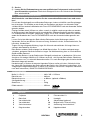
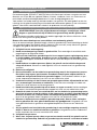
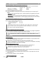
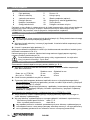
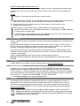
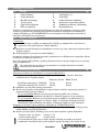
Overview
B Start up
A
1
23
1
7
3
6
* = optional
10
11
12
5
FF35120 FF35120
FF35121
FF35121
FF35120 = Ø15 x 65mm
FF35121 = Ø20 x 85mm
FF35120
FF35121
4
89*
2
FF30030

Intro
DEUTSCH - Originalbetriebsanleitung!
Bedienungsanleitung bitte lesen und aufbewahren! Nicht wegwerfen! Bei Schäden durch
Bedienungsfehler erlischt die Garantie! Technische Änderungen vorbehalten!
Seite 2
ENGLISH
Please read and retain these directions for use. Do not throw them away! The warranty does not
cover
damage caused by incorrect use of the equipment! Subject to technical modifications!
Page 9
FRANÇAIS
Lire attentivement le mode d’emploi et le ranger à un endroit sûr! Ne pas le jeter! La garantie est
annulée lors de dommages dûs à une manipulation erronée! Sous réserve de modifications
techniques!
Page 15
ESPAÑOL
¡Por favor, lea y conserve el manual de instrucciones! ¡No lo tire! ¡En caso de daños por errores de
manejo, la garantía queda sin validez!
Modificaciones técnicas reservadas!
Página 22
ITALIANO
Per favore leggere e conservare le istruzioni per l´uso! Non gettarle via! In caso di danni dovuti ad
errori
nell´uso, la garanzia si estingue!
Ci si riservano modifiche tecniche!
Pagina 29
NEDERLANDS
Lees de handleiding zorgvuldig door en bewaar haar goed! Niet weggooien! Bij schade door
bedieningsfouten komt de garantieverlening te vervallen! Technische wijzigingen voorbehouden!
Bladzijde 36
PORTUGUES
Queiram ler e guardar o manual de instruções! Não deitar fora! Em caso de avarias por utilização
incorrecta, extingue
-
se a garantia!
Reservado o direito de alterações técnicas!
Pagina 43
DANSK
Læs betjeningsvejledningen, og gem den til senere brug! Smid den ikke ud! Skader, som måtte
opstå som følge af betjeningsfejl, medfører, at garantien mister sin gyldighed! Ret til tekniske
ændringer forbeholdes!
Side 50
SVENSKA
Läs igenom bruksanvisningen och förvara den väl! Kasta inte bort den! Garantin upphör om
apparaten har använts eller betjänats på ett felaktigt sätt!
Med reservation för tekniska ändringar!
Sida 56
NORSK
Les bruksanvisningen og oppbevar den vel! Ikke kast den! Oppstår skader på grunn av
betjeningsfeil
opphører garantiens gyldighet! Tekniske forandringer forbeholdes!
Side 62
SUOMI
Lue ja säilytä tämä käyttöohje! Älä heitä pois! Takuu ei kata käyttövirheistä aiheutuvia vahinkoja!
Oikeudet teknisiin muutoksi
in pidätetään!
Sivulta 68
POLSKI
Instrukcję obslugi proszę przeczytać i zachować! Nie wyrzucać! Przy uszkodzeniach wynikajacych z
bl
ę
dów obs
ł
ugi wygasa gwarancja! Zmiany techniczne zastrze
ż
one!
Strony 74
CESKY
Navod k obsluze si prosim přečtěte a uschovejte jej! Nevyhazujte jej! V pripade poškozeni
zpusobenem chybnou obsluhou zanika zaruka! Technicke změny jsou vyhrazeny!
Stránky 81
TÜRKÇE
Kullanim açiklamalarini lütfen dikkatlice okuyunuz ve bir yerde muhafaza ediniz! Çöpe atmayiniz!
Kullaniminda yapilan hatalar, garantinin silinmesine neden olur! Teknik deðiþiklikler yapma hakkimiz
saklidir!
Sayfa 87
MAGYAR
Kérjük, olvassa el és őrizze meg a kezelési utasítást! Ne dobja el! A helytelen kezelésből származó
károsodások esetén megszûnik a jótállás!
Mûszaki változtatások fenntartva!
Oldaltól 94
SLOVENSKO
Preberite navodila za uporabo in jih shranite! Ne odvrzite jih! Ob poškodbah zaradi napak v uporabi
preneha veljati garancija!
Pridržujemo si pravico do tehničnih sprememb!
Stran 101
БЪЛГАРСКИ
Прочетете внимателно и запазете инструкцията за експлоатация! Не я захвърляйте или
унищожавайте! При настъпили дефекти вследствие на неправилно обслужване гаранцията отпада!
Технически изменения по уреда са изключително в
компетенцията на фирмата производител!
Страница 108
ΕΛΛΗΝΙΚΑ
Οδηγίες χειρισμού παρακαλείσθε να τις διαβάσετε και να τις φυλάσσετε! Μην τις πετάξετε! Σε ζημιες
από σφάλματα χειρισμού παυει να ισχύει η εγγύηση! Με επιφύλαξη για τεχνικές αλλαγές!
Σελίδα 115
PУCCKИЙ
Прочтите инструкцию по эксплуатации и сохраняйте её для дальнейшего использования! B
случае поломки инструмента из-за несоблюдения инструкции клиент теряет право на
обслуживание по гарантии!
Bозможны технические изменения!
Страница 122

2
DEUTSCH
Inhalt Seite
1
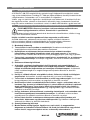
Hinweise zur Sicherheit ........................................................................................................ 3
1.1
Bestimmungsgemäße Verwendung .................................................................................... 3
1.2
Allgemeine Sicherheitshinweise für Elektrowerkzeuge........................................................ 3
1.3
Spezielle Sicherheitshinweise ............................................................................................. 5
2
Technische Daten ................................................................................................................. 5
3
Funktion des Gerätes ........................................................................................................... 5
3.1
Übersicht (A) ...................................................................................................................... 5
3.2
Inbetriebnahme .................................................................................................................. 6
3.3
Befestigungsmöglichkeiten (B) ........................................................................................... 6
3.4
Bedienung .......................................................................................................................... 7
4
Pflege und Wartung .............................................................................................................. 7
5
Zubehör ................................................................................................................................. 8
6
Kundendienst ........................................................................................................................ 8
7
Entsorgung............................................................................................................................ 8
Kennzeichnungen in diesem Dokument:
Gefahr!
Dieses Zeichen warnt vor Personenschäden.
Achtung!
Dieses Zeichen warnt vor Sach- oder Umweltschäden.
Aufforderung zu Handlungen

DEUTSCH
3
1 Hinweise zur Sicherheit
1.1 Bestimmungsgemäße Verwendung
Der Kernbohrständer RODIACUT 400 PRO dient ausschließlich zum Bohren von Löchern von
25 bis 400 mm (optional 500mm) Durchmesser in Beton, Stahlbeton, Kunst- und Naturstein und
Mauerwerk mit diamantbestückten Bohrkronen im Nass- oder Trockenbohrverfahren.
Für Arbeiten im oder unter Wasser sind die Bohrständer nicht geeignet. Jede darüber hinausge-
hende Verwendung sowie die Nichteinhaltung der Betriebsanleitung und/oder Wartungsbedie-
nungen gilt nicht als bestimmungsgemäß. Für hieraus resultierende Schäden haftet der Herstel-
ler nicht.
1.2 Allgemeine Sicherheitshinweise für Elektrowerkzeuge
WARNUNG! Lesen Sie alle Sicherheitshinweise, Anweisungen, Bebilderungen
und technischen Daten, mit denen dieses Elektrowerkzeug versehen ist.
Versäumnisse bei der Einhaltung der nachfolgenden Anweisungen können elektrischen Schlag,
Brand und/oder schwere Verletzungen verursachen.
Bewahren Sie alle Sicherheitshinweise und Anweisungen für die Zukunft auf.
Der in den Sicherheitshinweisen verwendete Begriff „Elektrowerkzeug“ bezieht sich auf netzbe-
triebene Elektrowerkzeuge (mit Netzkabel) und auf akkubetriebene Elektrowerkzeuge (ohne
Netzkabel).
1) Arbeitsplatzsicherheit
a) Halten Sie Ihren Arbeitsbereich sauber und gut beleuchtet. Unordnung oder unbeleuch-
tete Arbeitsbereiche können zu Unfällen führen.
b) Arbeiten Sie mit dem Elektrowerkzeug nicht in explosionsgefährdeter Umgebung, in
der sich brennbare Flüssigkeiten, Gase oder Stäube befinden. Elektrowerkzeuge er-
zeugen Funken, die den Staub oder die Dämpfe entzünden können.
c) Halten Sie Kinder und andere Personen während der Benutzung des Elektro-
werkzeugs fern. Bei Ablenkung können Sie die Kontrolle über das Elektrowerkzeug verlie-
ren.
2) Elektrische Sicherheit
a) Der Anschlussstecker des Elektrowerkzeuges muss in die Steckdose passen. Der
Stecker darf in keiner Weise verändert werden. Verwenden Sie keine Adapterstecker
gemeinsam mit schutzgeerdeten Elektrowerkzeugen. Unveränderte Stecker und pas-
sende Steckdosen verringern das Risiko eines elektrischen Schlages.
b) Vermeiden Sie Körperkontakt mit geerdeten Oberflächen, wie von Rohren, Heizungen,
Herden und Kühlschränken. Es besteht ein erhöhtes Risiko durch elektrischen Schlag,
wenn Ihr Körper geerdet ist.
c) Halten Sie Elektrowerkzeuge von Regen oder Nässe fern. Das Eindringen von Wasser in
ein Elektrogerät erhöht das Risiko eines elektrischen Schlages.
d) Zweckentfremden Sie die Anschlussleitung nicht, um das Elektrowerkzeug zu tragen,
aufzuhängen oder um den Stecker aus der Steckdose zu ziehen. Halten Sie die An-
schlussleitung fern von Hitze, Öl, scharfen Kanten oder sich bewegenden Teilen. Be-
schädigte oder verwickelte Kabel erhöhen das Risiko eines elektrischen Schlages.
e) Wenn Sie mit einem Elektrowerkzeug im Freien arbeiten, verwenden Sie nur Verlänge-
rungskabel, die auch für den Außenbereich geeignet sind. Die Anwendung eines für
den Außenbereich geeigneten Verlängerungsleitung verringert das Risiko eines elektrischen
Schlages.
f) Wenn der Betrieb des Elektrowerkzeuges in feuchter Umgebung nicht vermeidbar ist,
verwenden Sie einen Fehlerstromschutzschalter. Der Einsatz eines Fehlerstromschutz-
schalters vermindert das Risiko eines elektrischen Schlages.
3) Sicherheit von Personen
a) Seien Sie aufmerksam, achten Sie darauf, was Sie tun, und gehen Sie mit Vernunft an
die Arbeit mit einem Elektrowerkzeug. Benutzen Sie kein Elektrowerkzeug, wenn Sie
müde sind oder unter dem Einfluss von Drogen, Alkohol oder Medikamenten stehen.

4
DEUTSCH
Ein Moment der Unachtsamkeit beim Gebrauch des Elektrowerkzeuges kann zu ernsthaften
Verletzungen führen.
b) Tragen Sie persönliche Schutzausrüstung und immer eine Schutzbrille. Das Tragen
persönlicher Schutzausrüstung, wie Staubmaske, rutschfeste Sicherheitsschuhe, Schutz-
helm oder Gehörschutz, je nach Art und Einsatz des Elektrowerkzeuges, verringert das Ri-
siko von Verletzungen.
c) Vermeiden Sie eine unbeabsichtigte Inbetriebnahme. Vergewissern Sie sich, dass das
Elektrowerkzeug ausgeschaltet ist, bevor Sie es an die Stromversorgung und/oder
den Akku anschließen, es aufnehmen oder tragen. Wenn Sie beim Tragen des Elekt-
rowerkzeuges den Finger am Schalter haben oder das Elektrowerkzeug eingeschaltet an
die Stromversorgung anschließen, kann dies zu Unfällen führen.
d) Entfernen Sie Einstellwerkzeuge oder Schraubenschlüssel, bevor Sie das Elekt-
rowerkzeug einschalten. Ein Werkzeug oder Schlüssel, der sich in einem drehenden Teil
des Elektrowerkzeugs befindet, kann zu Verletzungen führen.
e) Vermeiden Sie eine abnormale Körperhaltung. Sorgen Sie für einen sicheren Stand
und halten Sie jederzeit das Gleichgewicht. Dadurch können Sie das Elektrowerkzeug in
unerwarteten Situationen besser kontrollieren.
f) Tragen Sie geeignete Kleidung. Tragen Sie keine weite Kleidung oder Schmuck. Hal-
ten Sie Haare, Kleidung und Handschuhe fern von sich bewegenden Teilen. Lockere
Kleidung, Schmuck oder lange Haare können von sich bewegenden Teilen erfasst werden.
g) Wenn Staubabsaug- und -Auffangeinrichtungen montiert werden können, sind diese
anzuschließen und richtig zu verwenden. Verwendung einer Staubabsaugung kann Ge-
fährdungen durch Staub verringern.
h) Wiegen Sie sich nicht in falscher Sicherheit und setzen Sie sich nicht über die Si-
cherheitsregeln für Elektrowerkzeuge hinweg, auch wenn Sie nach vielfachem Ge-
brauch mit dem Elektrowerkzeug vertraut sind. Achtloses Handeln kann binnen Sekun-
denbruchteilen zu schweren Verletzungen führen.
4) Verwendung und Behandlung des Elektrowerkzeuges
a) Überlasten Sie das Elektrowerkzeug nicht. Verwenden Sie für Ihre Arbeit das dafür
bestimmte Elektrowerkzeug. Mit dem passenden Elektrowerkzeug arbeiten Sie besser
und sicherer im angegebenen Leistungsbereich.
b) Benutzen Sie kein Elektrowerkzeug, dessen Schalter defekt ist. Ein Elektrowerkzeug,
das sich nicht mehr ein- oder ausschalten lässt, ist gefährlich und muss repariert werden.
c) Ziehen Sie den Stecker aus der Steckdose und/oder entfernen Sie einen abnehmba-
ren Akku, bevor Sie Geräteeinstellungen vornehmen, Zubehörteile wechseln oder das
Elektrowerkzeug weglegen. Diese Vorsichtsmaßnahme verhindert den unbeabsichtigten
Start des Elektrowerkzeuges.
d) Bewahren Sie unbenutzte Elektrowerkzeuge außerhalb der Reichweite von Kindern
auf. Lassen Sie keine Personen das Elektrowerkzeug benutzen, die mit diesem nicht
vertraut sind oder diese Anweisungen nicht gelesen haben. Elektrowerkzeuge sind ge-
fährlich, wenn Sie von unerfahrenen Personen benutzt werden.
e) Pflegen Sie Elektrowerkzeuge und Einsatzwerkzeuge mit Sorgfalt. Kontrollieren Sie,
ob bewegliche Geräteteile einwandfrei funktionieren und nicht klemmen, ob Teile ge-
brochen oder so beschädigt sind, dass die Funktion des Elektrowerkzeuges beein-
trächtigt ist. Lassen Sie beschädigte Teile vor dem Einsatz des Elektrowerkzeuges
reparieren. Viele Unfälle haben ihre Ursache in schlecht gewarteten Elektrowerkzeugen.
f) Halten Sie Schneidwerkzeuge scharf und sauber. Sorgfältig gepflegte Schneidwerk-
zeuge mit scharfen Schneidkanten verklemmen sich weniger und sind leichter zu führen.
g) Verwenden Sie Elektrowerkzeug, Einsatzwerkzeug, Einsatzwerkzeuge usw. entspre-
chend diesen Anweisungen. Berücksichtigen Sie dabei die Arbeitsbedingungen und
die auszuführende Tätigkeit. Der Gebrauch von Elektrowerkzeugen für andere als die
vorgesehenen Anwendungen kann zu gefährlichen Situationen führen.
h) Halten Sie Griffe und Griffflächen trocken, sauber und frei von Öl und Fett. Rutschige
Griffe und Griffflächen erlauben keine sichere Bedienung und Kontrolle des Elektrowerk-
zeugs in unvorhergesehenen Situationen.

DEUTSCH
5
5) Service
a) Lassen Sie Ihr Elektrowerkzeug nur von qualifiziertem Fachpersonal und nur mit Ori-
ginal-Ersatzteilen reparieren. Damit wird sichergestellt, dass die Sicherheit des Elektroge-
rätes erhalten bleibt.
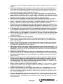
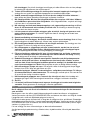
1.3 Spezielle Sicherheitshinweise
Alle Sicherheits- und Arbeitshinweise für den verwendeten Bohrmotor lesen und verste-
hen!
Die mit dem Kernbohrgerät auszuführenden Bohrungen sind ausschließlich vom Bauauftragge-
ber festzulegen. Für Schäden an der Statik von Bauwerken und daraus resultierende Folge-
schäden können weder die Mitarbeiter der Firma ROTHENBERGER noch der Anwender haftbar
gemacht werden.
Etwaige Schäden durch Kühlwasser sollten so weit als möglich vorab ausgeschlossen werden.
In Abstimmung mit der Bauleitung müssen erforderliche Gegenmaßnahmen getroffen werden.
Für verdeckte Wasserschäden (Hohlräume, Fugen, Risse, nicht sichtbare Rohre usw.) können
weder die Mitarbeiter der Firma ROTHENBERGER noch der Anwender haftbar gemacht wer-
den.
Lassen Sie bei der Montage des Bohrständers/Bohrmotors keine Werkzeuge stecken!
Verwenden Sie ihre persönliche Schutzausrüstung: Sicherheitsschuhe, Schutzhandschuhe, Ge-
hörschutz, Staubmaske!
Tragen Sie eng anliegende Kleidung, legen Sie Schmuck ab und binden Sie lange Haare zu-
sammen oder bedecken Sie diese.
Beim Bohren wird der Geräuschpegel von 90 db überschritten. Es ist daher zwingend vorge-
schrieben, geeignete Gehörschutzmittel zu tragen. Bei Nichtbeachtung kann es zu erheblichen
Gehörschäden kommen!
Während des Bohrens hat der Bediener das Bohrgerät aufmerksam zu beobachten. Bei ersten
Anzeichen für etwaige Störfälle (z.B. Kühlwasserausfall, sich lösender Bohrständer, Blockieren
der Bohrkrone usw.) ist sofort der Motor abzustellen. Erst nach Beseitigung der Ursache darf die
Bohrarbeit fortgesetzt werden.
Kernbohrungen in Decken mit darunter liegenden Räumen stellen ein hohes Sicherheitsrisiko
dar. Nach dem Durchbohren der Decke besteht die Gefahr, dass Bohrkerne herabstürzen. Hier
sind geeignete Gegenmaßnahmen zu treffen (z.B. Bereiche sichern bzw. absperren, Bohrkerne
nach oben entnehmen): BAUSTELLENABSICHERUNG.
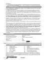
2 Technische Daten
Maße (L x B x H) ........................................ 460 x 305 x 1150 mm
Bohrhub max. ............................................ 680 mm
Bohrdurchmesser ....................................... ø 400mm (optional ø 500mm)
Schrägabstützung .......................................
ja
Gewicht ca. ................................................. 28 kg
Dübelsetzmaß ............................................ 350 mm
3 Funktion des Gerätes
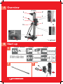
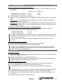
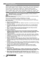
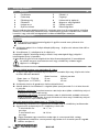
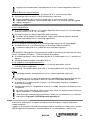
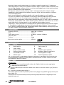
3.1 Übersicht (A)
1 Fußplatte 7 Feinvorschub 1:3
2 Bohrsäule 8 Handgriff
3 Vorschubeinheit 9 Absprießkopf (optional)
4 Vorschubhebel 10 Magnetischer Tiefenanschlag
5 Sechskantmutter 11 Arretierung Vorschubeinheit
6 Ringschrauben 12 Kippklemmhebel

6
DEUTSCH
Da das System aus aufeinander abgestimmte Komponenten besteht, verwenden Sie aus-
schließlich Original ROTHENBERGER Ersatzteile, Zubehör und Diamantbohrkronen, um jeder-
zeit die optimale Funktionsfähigkeit des Gerätes zu ermöglichen.
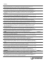
3.2 Inbetriebnahme
Positionierung:
Auf Position der Ringschrauben (6) achten! Ringschrauben dürfen nicht von der Unterkan-
te Bodenplatte überstehen!
Bohrloch vermessen und Bohrlochmitte anzeichnen. Dübelsetzmaß siehe technische Daten!
Fußplatte (1) justieren und befestigen.
Die jeweils optimale Befestigungsmöglichkeit ist von den Gegebenheiten der Baustelle abhängig
(siehe Befestigungsmöglichkeiten Pkt. 3.3).
Die abschließende Feinausrichtung bzw. Justierung des Bohrständers erreichen Sie durch an-
ziehen der vier Ringschrauben (6).
Vor jeder Inbetriebnahme sicherstellen, dass der Bohrständer fest fixiert ist und nicht
wackelt!
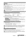
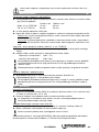
3.3 Befestigungsmöglichkeiten (B)
Dübelbefestigung in Beton oder Mauerwerk (Bild B-1):
Befestigungsloch für Dübelbefestigung vermessen und bohren. Dübelsetzmaß siehe tech-
nische Daten!
Durchmesser in mm Tiefe in mm
Beton (Art. Nr. FF35120) 15 mm 65 mm
Mauerwerk (Art. Nr. FF35121) 20 mm 85 mm
Bohrloch sorgfältig vom Bohrmehl säubern.
Betondübel mit Spreizkeil bzw. Mauerwerksdübel (bis 5 x wieder verwendbar) einsetzen.
Betonset: Kordelgewindestange in Dübel eindrehen. Bohrständer aufsetzen mit U-Scheibe
und Mutter fest anziehen.
Mauerwerkset: Kordelgewindestange mit Unterlegscheibe und montierter Mutter in den
Anker einschrauben. Mutter mit Gabelschlüssel anziehen. Bohrständer aufsetzen mit U-
Scheibe und Mutter fest anziehen.
Verspannung mit der Schnellspannsäule (Art. Nr. FF35015 Bild B-2):
Bohrständer ausrichten und Schnellspannsäule auf die Bodenplatte des Bohrständers auf-
setzen.
Schnellspannsäule ausfahren und Bohrständer festklemmen.
Mindesthöhe des Raumes: ca. 1,7 m
Max. Höhe des Raumes: ca. 3,0 m
Um Beschädigungen durch die Schnellspannsäule an Decken oder Wänden vorzubeugen,
legen Sie, zur Verteilung des Anpressdruckes auf eine größere Fläche, ein Stück Holz
oder ähnliches zwischen Säulenende und Decke!
Beigefügte Bedienungsanleitung der Schnellspannsäule lesen und verstehen!
Optional: Verspannung mit Absprießkopf:
Geeignetes Distanzstück zwischen Absprießkopf (9) und Wand/Decke setzen.
Absprießkopf herausdrehen und somit Bohrständer festklemmen.
Um B
eschädigungen durch das Distanzstück an Decken oder Wänden vorzubeugen,
legen Sie, zur Verteilung des Anpressdruckes auf eine größere Fläche, ein Stück Holz
oder ähnliches zwischen Säulenende und Decke!

DEUTSCH
7
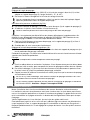
3.4 Bedienung
Bohrwinkel einstellen:
Sechskantmuttern SW24 (5) und Kippklemmhebel (12) lösen und Bohrsäule (2) auf ge-
wünschten Winkel (-15 -0- 45°) einstellen.
Sechskantmuttern und Kippklemmhebel wieder anziehen.
Beim Festziehen der Sechskantmuttern darauf achten, dass die Verzahnung der Stütz-
platte formschlüssig in die Verzahnung der Bohrsäule eingreift!
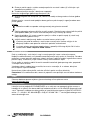
Diamantbohrmaschine einsetzen (Bild B-3):
Arretierung (11) lösen und Vorschubeinheit (3) von Bohrsäule (2) entnehmen.
Motor mit beiliegenden Schrauben an Vorschubeinheit (3) befestigen.
Auf richtige Lage der Pa
ssfedernut und Bohrungen achten!
Für eine Erweiterung des Bohrbereiches für RODIADRILL 500 können optional zusätzliche Dis-
tanzplatten verwendet werden: Bohrkronen Ø 500mm = FF35136 Distanzplatte 60mm.
Vorschubeinheit mit Bohrmotor auf Bohrsäule (2) einschieben und mittels Arretierung (11)
fixieren.
Zum Entnehmen in umgekehrter Reihenfolge vorgehen.
Magnetischen Tiefenanschlag (10) einstellen:
Magnetischen Tiefenanschlag (10) auf die Verzahnung der Bohrsäule in gewünschter Bohr-
tiefe stecken.
Bohrtiefe = Abstand zwischen Unterkante Vorschubgetriebe und Oberkante Tiefenanschlag.
Bohren:
Bedienungsanleitung zum Bohrmotor lesen und verstehen!
Wasserhahn aufdrehen bzw. Staubsauger einschalten. Es muss mindestens so viel Was-
serdruck (max. 4 bar!) vorhanden sein, dass die anfallenden Bohrschlämme aus dem Bohr-
loch gefördert werden.
Arretierung (11) Vorschubeinheit lösen und mit Vorschubhebel (4) Bohrmaschine bis zur
gewünschten Bohrtiefe herunterdrehen.
Motor ausschalten und Zurückkurbeln, bis die Bohrkrone vollständig sichtbar ist.
Sollte ein Klemmen auftreten, Bohrmotor mit niedriger Drehzahl unter Kühlwasser wieder
anfahren und Bohrkrone zurückziehen!
Notfalls den Vorgang wiederholen bzw. mittels Gabelschlüssel SW 41 an der Bohrkrone
drehen.
Achtung: PRCD Schalter ausschalten!
4 Pflege und Wartung
Arbeiten zur Instandhaltung, Wartung und Pflege dürfen nur im Anlagestillstand durchgeführt
werden.
Die besten Instandhaltungsmaßnahmen sind das tägliche Entfernen von Schlamm, Staub und
Schmutz. Besonderes Augenmerk ist auf Führungssäule und Gleitführung sowie auf Zahnstan-
ge und Vorschubritzel zu legen. Die Spindel sollte nach jeder Reinigung leicht eingeölt werden.
Die Gleitführungen sind in regelmäßigen Abständen auf Spiel zu kontrollieren und bei Bedarf
nachzustellen.
Bohrsäule und Zahnstange nicht fetten, da das Fett mit dem anhaftenden Schmutz wie
eine Schleifpaste wirkt und den Verschleiß erhöht!
Die Stellschrauben der Fußplatte täglich reinigen und leichtgängig halten.
Wichtig! Alle Wartungs-, Instandsetzungs- und Reparaturarbeiten dürfen nur von eingewiese-
nem Fachpersonal durchgeführt werden.

8
DEUTSCH
5 Zubehör
Geeignetes Zubehör finden Sie im Hauptkatalog oder unter www.rothenberger.com
6 Kundendienst
Die ROTHENBERGER Kundendienst-Standorte stehen zur Verfügung, um Ihnen zu helfen (sie-
he Liste im Katalog oder online), und Ersatzteile und Kundendienst werden durch dieselben
Standorte angeboten. Bestellen Sie Ihre Zubehör- und Ersatzteile bei Ihrem Fachhändler oder
online über RO SERVICE+: ℡ + 49 (0) 61 95/ 800 8200 + 49 (0) 61 95/ 800 7491
service@rothenberger.com - www.rothenberger.com
7 Entsorgung
Teile des Gerätes sind Wertstoffe und können der Wiederverwertung zugeführt werden. Hierfür
stehen zugelassene und zertifizierte Verwerterbetriebe zur Verfügung. Zur umweltverträglichen
Entsorgung der nicht verwertbaren Teile (z.B. Elektronikschrott) befragen Sie bitte Ihre zustän-
dige Abfallbehörde.
Nur für EU-Länder:
Werfen Sie Elektrowerkzeuge nicht in den Hausmüll! Gemäß der Europäischen Richtli-
nie 2012/19/EU über Elektro- und Elektronik-Altgeräte und ihrer Umsetzung in nationa-
les Recht müssen nicht mehr gebrauchsfähige Elektrowerkzeuge getrennt gesammelt
und einer umweltgerechten Wiederverwertung zugeführt werden.

ENGLISH
9
Contents Page
1
Safety Notes ........................................................................................................................ 10
1.1
Intended use..................................................................................................................... 10
1.2
General Power Tool Safety Warnings ............................................................................... 10
1.3
Special Safety Instructions ............................................................................................... 11
2
Technical Data .................................................................................................................... 12
3
Function of the Unit ............................................................................................................ 12
3.1
Overview (A) ..................................................................................................................... 12
3.2
Start of operation .............................................................................................................. 12
3.3
Fastening possibilities (B) ................................................................................................. 13
3.4
Handling ........................................................................................................................... 13
4
Care and Maintenance ........................................................................................................ 14
5
Accessories......................................................................................................................... 14
6
Customer service ................................................................................................................ 14
7
Disposal ............................................................................................................................... 14
Markings in this document:
Markings in this document!
This sign warns against the danger of personal injuries.
Caution!
This sign warns against the danger of property damage and damage to the environment.
Call for action

10
ENGLISH
1 Safety Notes
1.1 Intended use
The RODIACUT 400 PRO core drill rig serves exclusively to drill holes of 25 to 400 mm (optional
500mm) in diameter in concrete, reinforced concrete, artificial and natural stone and brickwork
using diamond-equipped core bits for the wet or dry drilling process.
The drill rigs are not suitable for work in or under water. Every application beyond this as well as
failure to comply with the instructions for use and/or maintenance handling shall be regarded as
not in accordance with regulations. The manufacturer shall not be liable for damages as a result
of this.
1.2 General Power Tool Safety Warnings
WARNING
! Read all safety warnings, instructions, illustrations and specifications
provided with this power tool.
Failure to follow all instructions listed below may result in electric shock, fire and/or serious inju-
ry.
Save all warnings and instructions for future reference.
The term “power tool” in the warnings refers to your electrically-operated (corded) power tool or
battery-operated (cordless) power tool.
1) Work area safety
a) Keep work area clean and well lit. Cluttered and dark areas invite accidents.
b) Do not operate power tools in explosive atmospheres, such as in the presence of
flammable liquids, gases or dust. Power tools create sparks which may ignite the dust or
fumes.
c) Keep children and bystanders away while operating a power tool. Distractions can
cause you to lose control.
2) Electrical safety
a) Power tool plugs must match the outlet. Never modify the plug in any way. Do not use
any adapter plugs with earthed (grounded) power tools. Unmodified plugs and matching
outlets will reduce risk of electric shock.
b) Avoid body contact with earthed or grounded surfaces, such as pipes, radiators,
ranges and refrigerators. There is an increased risk of electric shock if your body is
earthed or grounded.
c) Do not expose power tools to rain or wet conditions. Water entering a power tool will in-
crease the risk of electric shock.
d) Do not abuse the cord. Never use the cord for carrying, pulling or unplugging the
power tool. Keep cord away from heat, oil, sharp edges and moving parts. Damaged or
entangled cords increase the risk of electric shock.
e) When operating a power tool outdoors only, use an extension cords suitable for out-
door use. Use of a cord suitable for outdoor use reduces the risk of electric shock.
f) If operating a power tool in a damp location is unavoidable, use a residual current de-
vice (RCD) protected supply. Use of an RCD reduces the risk of electric shock.
3) Personal safety
a) Stay alert, watch what you are doing and use common sense when operating a power
tool. Do not use a power tool while you are tired or under the influence of drugs, al-
cohol or medication. A momentary lack of attention while operating power tools may result
in serious personal injury.
b) Use personal protective equipment. Always wear eye protection. Protective equipment
such as dust mask, non-skid safety shoes, hard hat, or hearing protection used for appropri-
ate conditions will reduce personal injuries.
c) Prevent unintentional starting. Ensure the switch is in the off-position before connect-
ing to power source and/or battery pack, picking up or carrying the tool. Carrying

ENGLISH
11
power tools with your finger on the switch or energising power tools that have the switch on
invites accidents.
d) Remove any adjusting key or wrench before turning the power tool on. A wrench or a
key left attached to a rotating part of the power tool may result in personal injury.
e) Do not overreach. Keep proper footing and balance at all times. This enables better
control of the power tool in unexpected situations.
f) Dress properly. Do not wear loose clothing or jewellery. Keep your hair, clothing and
gloves away from moving parts. Loose clothes, jewellery or long hair can be caught in
moving parts.
g) If devices are provided for the connection of dust extraction and collection facilities,
ensure these are connected and properly used. Use of dust collection can reduce dust-
related hazards.
h) Do not let familiarity gained from frequent use of tools allow you to become compla-
cent and ignore tool safety principles. A careless action can cause severe injury within a
fraction of a second.
4) Power tool use and care
a) Do not force the power tool. Use the correct power tool for your application. The cor-
rect power tool will do the job better and safer at the rate for which it was designed.
b) Do not use the power tool if the switch does not turn it on and off. Any power tool that
cannot be controlled with the switch is dangerous and must be repaired.
c) Disconnect the plug from the power source and/or remove the battery pack, if de-
tachable, from the power tool before making any adjustments, changing accessories,
or storing power tools. Such preventive safety measures reduce the risk of starting the
power tool accidentally.
d) Store idle power tools out of the reach of children and do not allow persons unfamil-
iar with the power tool or these instructions to operate the power tool. Power tools are
dangerous in the hands of untrained users.
e) Maintain power tools and accessories. Check for misalignment or binding of moving
parts, breakage of parts and any other condition that may affect the power tool’s op-
eration. If damaged, have the power tool repaired before use. Many accidents are
caused by poorly maintained power tools.
f) Keep cutting tools sharp and clean. Properly maintained cutting tools with sharp cutting
edges are less likely to bind and are easier to control.
g) Use the power tool, accessories and tool bits etc., in accordance with these instruc-
tions, taking into account the working conditions and the work to be performed. Use
of the power tool for operations different from those intended could result in a hazardous sit-
uation.
h) Keep handles and grasping surfaces dry, clean and free from oil and grease. Slippery
handles and grasping surfaces do not allow for safe handling and control of the tool in unex-
pected situations.
5) Service
a) Have your power tool serviced by a qualified repair person using only identical re-
placement parts. This will ensure that the safety of the power tool is maintained.
1.3 Special Safety Instructions
Please read and be sure to understand all safety and working information for the drill mo-
tor being used!
The drilling to be carried out with the core drill must be stipulated exclusively by the construction
customer. Neither the ROTHENBERGER employees nor the user can be held liable for damag-
es to the construction statics and consequential damages as a result of this.
Any damages due to cooling water must be excluded as far as possible in advance. Necessary
countermeasures must be taken in coordination with construction site management. Neither the
ROTHENBERGER employees nor the user can be held liable for concealed water damages
(cavities, joints, cracks, invisible pipes etc.).

12
ENGLISH
Do not leave any tools inserted during the installation of the drill rig/drill motor.
Use your personal protective equipment: safety shoes, protective gloves, ear protectors, dust
mask.
Wear close-fitting clothing, remove jewellery and tie back or cover long hair.
The 90 dB noise level is exceeded during drilling. It is, therefore, mandatory to wear suitable ear
protection. Non-observance can lead to significant hearing damage.
The operator must observe the drilling equipment attentively during drilling. Shut down the motor
immediately at the first sign of any disturbances (e.g. cooling water deficiency, loosening of the
drill rig, core bit blocked etc.). Drilling work must only be continued after the cause has been
remedied.
Core hole drilling in ceilings with rooms underneath constitutes a high safety risk. After drilling
through the ceiling there is the danger of the drilling cores crashing down. Suitable counter-
measures must be taken (e,g. safeguard or close off areas, remove drilling cores in an upward
direction): SAFEGUARD THE BUILDING SITE.
2 Technical Data
Dimensions (LxWxH) .................................. 460 x 305 x 1150 mm
Drill stroke max ........................................... 680 mm
Drill diameter max ....................................... ø 400mm (optional ø 500mm)
Sloping support ........................................... yes
Weight ca. .................................................. 28 kg
Dowel depth extent ..................................... 350 mm
3 Function of the Unit
3.1 Overview (A)
1 Base plate 7 Fine feed 1:3
2 Drill column 8 Hand grip
3 feed unit 9 Strut head (optional)
4 Advance lever 10 Magnetic depth stop
5 Hexagon nut 11 Feeder locking device
6 Eye bolts 12 Rocking clamp lever
As the system consists of coordinated components, please only use original ROTHENBERGER
spare parts, accessories and diamond drill bits in order to enable optimum efficiency of the
equipment at all times.
3.2 Start of operation
Positioning:
Please pay attention to the position of the ring bolts (6)! Ring bolts must not overlap the
lower edge of the base plate
!
Measure borehole and mark the centre. See technical data for extent of dowel depth!
Adjust and fasten base plate (1).
The respective optimum fastening possibility depends on the building site conditions (see fas-
tening possibilities, item 3.3).
You can achieve the final fine alignment or adjustment of the drill rig by tightening the four ring
bolts (6).
Every time before start of operation make sure that the drill rig is firmly fastened and
not able to shake
!

ENGLISH
13
3.3 Fastening possibilities (B)
Dowel fastening on concrete or brickwork (fig. B-1):
Measure and drill a mounting hole for the dowel fastening. See technical data for extent of
dowel depth!
Diameter in mm
Depth in mm
Concrete (Item no. FF35120) 15 mm 65 mm
Brickwork (Item no. FF35121) 20 mm 85 mm
Carefully clean the drill dust from the borehole.
Apply the concrete dowel with expansion wedge or brickwork dowel (can be re-used up to 5
times).
Concrete set: Turn the diamond knurl threaded bar into the dowel, attach the drill rig and
fasten using the U-washer and nut.
Brickwork set: Screw the diamond knurl threaded bar with the grommet and mounted nut in-
to the armature. Tighten the nut using an open-ended spanner. Attach the drill rig and fasten
using the U-washer and nut.
Bracing with the quick clamp column (Item no. FF35015 fig. B-2):
Align the drill rig and attach the quick clamp column to the base plate of the drill rig.
Extend the quick clamp column and clamp the drill rig.
Minimum room height: ca. 1,7 m
Maximum room height: ca. 3,0 m
In order to avoid damage to the ceilings or
walls by the quick clamp column, place a piece
of wood or similar between the end of the column and the ceiling to distribute the contact
pressure over a larger area
!
Please read and be sure to understand the supplied quick clamp column
instruction
manual
!
Optional: Bracing with the strut head:
Place a suitable spacer between the strut head (9) and wall/ceiling.
Unscrew the strut head and consequently clamp the drill rig.
In order to prevent damages to the ceilings or walls due to t
he spacer, place a piece of
wood or similar between the end of the column and the ceiling in order to distribute the
contact pressure over a greater area
!
3.4 Handling
Setting the drill angle:
Loosen the SW24 hexagon nuts (5) and rocking clamp lever (12) and set the drill column (2)
to the desired angle (-15 -0- 45°).
Re-tighten the hexagon nuts and rocking clamp lever.
When tightening the hexagon nuts please ensure that the toothing of the retaining
plate
engages positively in the toothing of the drill
column!
Applying the diamond drill (fig. B-3):
Loosen the locking device (11) and remove the feed unit (3) from the drill column (2).
Use the supplied screws to fasten the motor to the feed unit (3).
Please observe the correct position of the
feather key groove and the drill holes!
Additional distance plates can be used as an option in order to expand the drilling range for drill
motor RODIADRILL 500: Drill bits diameter 500mm = FF35136 Distance plate 60mm.
Insert the feed unit with the drill motor into the drill column (2) and use the locking device
(11) to fasten.
Proceed in the reverse order in order to remove.

14
ENGLISH
Setting the magnetic depth stop:
Insert the magnetic depth stop (10) into the toothing of the drill column to the desired drill
depth.
Drill depth = distance between bottom edge of the feed gear and top edge of the depth stop.
Drilling:
Please read and be sure to understand the drill motor instruction manual
!
Turn on the water tap or switch on the vacuum cleaner. There must at least be sufficient wa-
ter pressure (max. 4 bar!) to move the arising drill-ng mud from the borehole.
Release the locking device (11) on the feed gear and use the hand wheel (4) to turn the drill
downward to the desired drill depth.
Switch off the motor and crank back until the drill bit is completely visible.
In case of seizure, start up the drill motor again at low speed using cooling water and
withdraw the core bit
!
In case of need, repeat the process or turn the core bit using the SW 41 flat wrench.
Please note: Switch off the RCD s
witch!
4 Care and Maintenance
Upkeep, servicing and maintenance work must only be carried out when the system is at a
standstill.
The best maintenance measures involve the daily removal of sludge, dust and dirt. Special at-
tention must be paid to the guide column and sliding guide as well as to the gear rack and the
feed bevel. The spindle should be oiled lightly each time it is cleaned.
The sliding guides should be checked for play at regular intervals and re-adjusted if necessary.
Do not grease the drill column and gear rack as the grease takes effect as a grinding
paste together with the adherent dirt and increases wear.
Clean the adjusting screws on the base plate every day and keep them free-moving.
Important! All maintenance, overhauling and repair work must only be carried out by trained
specialised staff.
5 Accessories
You can find suitable accessories in the main catalog or at www.rothenberger.com
6 Customer service
The ROTHENBERGER service locations are available to help you (see listing in catalog or on-
line) and replacement parts and service are also available through these same service locations.
Order your accessories and spare parts from your specialist retailer or using RO SERVICE+
online: ℡ + 49 (0) 61 95/ 800 8200 + 49 (0) 61 95/ 800 7491 service@rothenberger.com -
www.rothenberger.com
7 Disposal
Components of the unit are recyclable material and should be put to recycling. For this purpose
registered and certified recycling companies are available. For an environmental friendly dispos-
al of the non-recyclable parts (e.g. electronic waste) please contact your local waste disposal
authority.
For EU countries only:
Do not dispose electric tools with domestic waste. In accordance with the European
Directive 2012/19/EU the disposal of electrical and electronic equipment and its imple-
mentation as national law, electric tools that are no longer serviceable must be collected
separately and utilised for environmentally compatible recycling.

FRANÇAIS
15
Table des matières Page
1
Consignes de sécurité ........................................................................................................ 16
1.1
Utilisation conforme aux dispositions ................................................................................ 16
1.2
Avertissements de sécurité généraux pour l’outil .............................................................. 16
1.3
Instructions de sécurité ..................................................................................................... 18
2
Données techniques ........................................................................................................... 18
3
Fonctionnement de l'appareil ............................................................................................. 18
3.1
Vue d'ensemble (A) .......................................................................................................... 18
3.2
Mise en service ................................................................................................................ 19
3.3
Befestigungsmöglichkeiten (B) ......................................................................................... 19
3.4
Maniement ....................................................................................................................... 20
4
Entretien et maintenance ................................................................................................... 20
5
Accessoires......................................................................................................................... 21
6
Service à la clientèle ........................................................................................................... 21
7
Elimination des déchets ..................................................................................................... 21
Pictogrammes contenus dans ce document:
Danger!
Ce pictogramme signale un risque de blessure pour les personnes.
Attention!
Ce pictogramme signale un risque de dommage matériel ou de préjudice pour
l’environnement.
Nécessité d’exécuter une action

16
FRANÇAIS
1 Consignes de sécurité
1.1 Utilisation conforme aux dispositions
Le support de perçage RODIACUT 400 PRO est prévu exclusivement pour le perçage de trous
d'un diamètre de 25 à 400mm (optional 500 mm) dans le béton, le béton armé, la pierre synthé-
tique et naturelle et la maçonnerie à l'aide de couronnes de perçage diamantées en forage à
l'eau ou à sec.
Les supports de perçage ne conviennent pas à une utilisation dans ou sous l'eau. Toute autre
utilisation ainsi que le non-respect des instructions d'utilisation et / ou des consignes d'entretien
sont considérés comme non conformes à la destination prévue. Le fabricant ne répond pas des
dommages résultant d'une telle utilisation.
1.2 Avertissements de sécurité généraux pour l’outil
AVERTISSEMENT! Lire tous les avertissements de sécurité, les instructions, les
illustrations et les spécifications fournis avec cet outil électrique.
Ne pas suivre les instructions énumérées ci-dessous peut provoquer un choc électrique, un in-
cendie et/ou une blessure sérieuse.
Conserver tous les avertissements et toutes les instructions pour pouvoir s’y reporter ul-
térieurement.
Le terme « outil » dans les avertissements fait référence à votre outil électrique alimenté par le
secteur (avec cordon d’alimentation) ou votre outil fonctionnant sur batterie (sans cordon
d’alimentation).
1) Sécurité de la zone de travail
a) Conserver la zone de travail propre et bien éclairée. Les zones en désordre ou sombres
sont propices aux accidents.
b) Ne pas faire fonctionner les outils électriques en atmosphère explosive, par exemple
en présence de liquides inflammables, de gaz ou de poussières. Les outils électriques
produisent des étincelles qui peuvent enflammer les poussières ou les fumées.
c) Maintenir les enfants et les personnes présentes à l’écart pendant l’utilisation de
l’outil. Les distractions peuvent vous faire perdre le contrôle de l'outil.
2) Sécurité électrique
a) Il faut que les fiches de l’outil électrique soient adaptées au socle. Ne jamais modifier
la fiche de quelque façon que ce soit. Ne pas utiliser d’adaptateurs avec des outils à
branchement de terre. Des fiches non modifiées et des socles adaptés réduiront le risque
de choc électrique.
b) Evitez le contact physique avec des surfaces mises à la terre tels que tuyaux, radia-
teurs, fours et réfrigérateurs. Il y a un risque élevé de choc électrique au cas où votre
corps serait relié à la terre.
c) N’exposez pas l’outil électroportatif à la pluie ou à l’humidité. La pénétration d’eau dans
un outil électroportatif augmente le risque d’un choc électrique.
d) Ne pas maltraiter le cordon. Ne jamais utiliser le cordon pour porter, tirer ou débran-
cher l'outil électrique. Maintenir le cordon à l'écart de la chaleur, du lubrifiant, des
arêtes vives ou des parties en mouvement. Des cordons endommagés ou emmêlés
augmentent le risque de choc électrique.
e) Lorsqu'on utilise un outil électrique à l'extérieur, utiliser un prolongateur adapté à
l'utilisation extérieure. L'utilisation d'un cordon adapté à l'utilisation extérieure réduit le
risque de choc électrique.
f) Si l’usage d’un outil dans un emplacement humide est inévitable, utiliser une alimen-
tation protégée par un dispositif à courant différentiel résiduel (RCD). L’usage d’un
RCD réduit le risque de choc électrique.
3) Sécurité des personnes
a) Restez vigilant, surveillez ce que vous faites. Faites preuve de bon en utilisant l’outil
électroportatif. N’utilisez pas l’appareil lorsque vous êtes fatigué ou après avoir con-
sommé de l’alcool, des drogues ou avoir pris des médicaments. Un moment

FRANÇAIS
17
d’inattention lors de l’utilisation de l’appareil peut entraîner de graves blessures sur les per-
sonnes.
b) Portez des équipements de protection. Portez toujours des lunettes de protection. Le
fait de porter des équipements de protection personnels tels que masque anti-poussières,
chaussures de sécurité antidérapantes, casque de protection ou protection acoustique sui-
vant le travail à effectuer, réduit le risque de blessures.
c) Eviter tout démarrage intempestif. S’assurer que l’interrupteur est en position arrêt
avant de brancher l’outil au secteur et/ou au bloc de batteries, de le ramasser ou de le
porter. Porter les outils électriques en ayant le doigt sur l'interrupteur ou brancher des outils
électriques dont l'interrupteur est en position marche est source d'accidents.
d) Retirer toute clé de réglage avant de mettre l'outil électrique en marche. Une clé lais-
sée fixée sur une partie tournante de l'outil électrique peut donner lieu à des blessures.
e) Ne pas se précipiter. Garder une position et un équilibre adaptés à tout moment. Cela
permet un meilleur contrôle de l'outil électrique dans des situations inattendues.
f) S'habiller de manière adaptée. Ne pas porter de vêtements amples ou de bijoux. Gar-
der les cheveux et les vêtements à distance des parties en mouvement. Des vêtements
amples, des bijoux ou les cheveux longs peuvent être pris dans des parties en mouvement.
g) Si des dispositifs sont fournis pour le raccordement d'équipements pour l'extraction
et la récupération des poussières, s'assurer qu'ils sont connectés et correctement
utilisés. Utiliser des collecteurs de poussière peut réduire les risques dus aux poussières.
h) Rester vigilant et ne pas négliger les principes de sécurité de l'outil sous prétexte que
vous avez l'habitude de l'utiliser. Une fraction de seconde d'inattention peut provoquer
une blessure grave.
4) Utilisation et entretien de l'outil électrique
a) Ne pas forcer l'outil électrique. Utiliser l'outil électrique adapté à votre application.
L'outil électrique adapté réalise mieux le travail et de manière plus sûre au régime pour le-
quel il a été construit.
b) Ne pas utiliser l'outil électrique si l'interrupteur ne permet pas de passer de l'état de
marche à arrêt et inversement. Tout outil électrique qui ne peut pas être commandé par
l'interrupteur est dangereux et il faut le réparer.
c) Débrancher la fiche de la source d'alimentation et/ou enlever le bloc de batteries, s'il
est amovible, avant tout réglage, changement d'accessoires ou avant de ranger l'outil
électrique. De telles mesures de sécurité préventives réduisent le risque de démarrage ac-
cidentel de l'outil électrique.
d) Conserver les outils électriques à l'arrêt hors de la portée des enfants et ne pas per-
mettre à des personnes ne connaissant pas l'outil électrique ou les présentes instruc-
tions de le faire fonctionner. Les outils électriques sont dangereux entre les mains d'utili-
sateurs novices.
e) Observer la maintenance des outils électriques et des accessoires. Vérifier qu'il n'y a
pas de mauvais alignement ou de blocage des parties mobiles, des pièces cassées
ou toute autre condition pouvant affecter le fonctionnement de l'outil électrique. En
cas de dommages, faire réparer l'outil électrique avant de l'utiliser. De nombreux acci-
dents sont dus à des outils électriques mal entretenus.
f) Garder affûtés et propres les outils permettant de couper. Des outils destinés à couper
correctement entretenus avec des pièces coupantes tranchantes sont moins susceptibles
de bloquer et sont plus faciles à contrôler.
g) Utiliser l'outil électrique, les accessoires et les lames etc., conformément à ces ins-
tructions, en tenant compte des conditions de travail et du travail à réaliser. L'utilisa-
tion de l'outil électrique pour des opérations différentes de celles prévues peut donner lieu à
des situations dangereuses.
h) Il faut que les poignées et les surfaces de préhension restent sèches, propres et dé-
pourvues d'huiles et de graisses. Des poignées et des surfaces de préhension glissantes
rendent impossibles la manipulation et le contrôle en toute sécurité de l'outil dans les situa-
tions inattendues.

18
FRANÇAIS
5) Service
a) Faire entretenir l'outil électrique par un réparateur qualifié utilisant uniquement des
pièces de rechange identiques. Cela assure le maintien de la sécurité de l'outil électrique.
1.3 Instructions de sécurité
Lire et comprendre les consignes de sécurité et les remarques concernant le travail pour
le moteur de perçage utilisé!
Les opérations de perçage à effectuer à l'aide de la perceuse doivent être définies exclusive-
ment par le maître d'ouvrage. Ni les collaborateurs de la société ROTHENBERGER ni l'utilisa-
teur ne pourront être rendus responsables d'un endommagement de la statique des ouvrages ni
des dommages en résultant.
Dans la mesure du possible, les endommagements dus à l'eau de refroidissement sont à ex-
clure dès le départ. Les mesures préventives sont à prendre en accord avec la direction des tra-
vaux. Ni les collaborateurs de la société ROTHENBERGER ni l'utilisateur ne pourront être ren-
dus responsables de dégâts des eaux cachés (cavités, joints, fissures, tuyaux non visibles, etc.).
Pendant le montage, ne pas laisser d'outils sur le support de perçage / le moteur de perçage !
Utilisez votre propre équipement de protection : chaussures de sécurité, gants de protection,
protection auditive, masque anti-poussière !
Portez des vêtements près du corps, retirez les bijoux, ramassez les cheveux longs ou couvrez-
les.
Lors du perçage, le niveau sonore de 90 db est dépassé. Par conséquent, le port de protections
auditives appropriées est indispensable. Le non-respect peut provoquer des lésions de l'ouïe !
Pendant le perçage, l'opérateur doit observer la perceuse attentivement. Le moteur est à couper
dès les moindres signes d'un dysfonctionnement (par exemple fuite d'eau de refroidissement,
support de perçage qui se détache, blocage de la couronne de perçage, etc.) L'opération de
perçage ne doit être reprise qu'après avoir éliminé la cause.
Le perçage dans des plafonds sous lesquels se trouvent des pièces comporte un grand risque.
Après le transpercement du plafond, il y a un risque de chute des couronnes de perçage. Il con-
vient de prendre les mesures préventives appropriées (par exemple protéger ou barrer l'accès
aux zones concernées, retirer les couronnes de perçage vers le haut) : PROTECTION DE
CHANTIER.
2 Données techniques
Dimensions LxIxH (mm) .............................. 460 x 305 x 1150 mm
Course maximale de perçage ..................... 680 mm
Diamètre de couronne max ......................... ø 400mm (optional ø 500mm)
Appui incliné ............................................... oui
Poids ca. ..................................................... 28 kg
Cote chevilles ............................................. 350 mm
3 Fonctionnement de l'appareil
3.1 Vue d'ensemble (A)
1 Plaque de fond 7 Avance 1:3
2 Support de perçage 8 Poignée
3 Unité d'avance 9 Tête d'étançonnement (optional)
4 Levier d'avance 10 Butée de profondeur magnétique
5 Ecrou hexagonal 11 Bouton de blocage avance
6 Vis à œillet 12 Levier de serrage à bascule
Comme le système est constitué de composants adaptés les uns aux autres, il est impératif
d'utiliser exclusivement des pièces détachées, des accessoires et des couronnes de perçage
diamantées de la marque ROTHENBERGER pour permettre à tout moment une fonctionnalité
optimale de l'appareil.
Sayfa yükleniyor...
Sayfa yükleniyor...
Sayfa yükleniyor...
Sayfa yükleniyor...
Sayfa yükleniyor...
Sayfa yükleniyor...
Sayfa yükleniyor...
Sayfa yükleniyor...
Sayfa yükleniyor...
Sayfa yükleniyor...
Sayfa yükleniyor...
Sayfa yükleniyor...
Sayfa yükleniyor...
Sayfa yükleniyor...
Sayfa yükleniyor...
Sayfa yükleniyor...
Sayfa yükleniyor...
Sayfa yükleniyor...
Sayfa yükleniyor...
Sayfa yükleniyor...
Sayfa yükleniyor...
Sayfa yükleniyor...
Sayfa yükleniyor...
Sayfa yükleniyor...
Sayfa yükleniyor...
Sayfa yükleniyor...
Sayfa yükleniyor...
Sayfa yükleniyor...
Sayfa yükleniyor...
Sayfa yükleniyor...
Sayfa yükleniyor...
Sayfa yükleniyor...
Sayfa yükleniyor...
Sayfa yükleniyor...
Sayfa yükleniyor...
Sayfa yükleniyor...
Sayfa yükleniyor...
Sayfa yükleniyor...
Sayfa yükleniyor...
Sayfa yükleniyor...
Sayfa yükleniyor...
Sayfa yükleniyor...
Sayfa yükleniyor...
Sayfa yükleniyor...
Sayfa yükleniyor...
Sayfa yükleniyor...
Sayfa yükleniyor...
Sayfa yükleniyor...
Sayfa yükleniyor...
Sayfa yükleniyor...
Sayfa yükleniyor...
Sayfa yükleniyor...
Sayfa yükleniyor...
Sayfa yükleniyor...
Sayfa yükleniyor...
Sayfa yükleniyor...
Sayfa yükleniyor...
Sayfa yükleniyor...
Sayfa yükleniyor...
Sayfa yükleniyor...
Sayfa yükleniyor...
Sayfa yükleniyor...
Sayfa yükleniyor...
Sayfa yükleniyor...
Sayfa yükleniyor...
Sayfa yükleniyor...
Sayfa yükleniyor...
Sayfa yükleniyor...
Sayfa yükleniyor...
Sayfa yükleniyor...
Sayfa yükleniyor...
Sayfa yükleniyor...
Sayfa yükleniyor...
Sayfa yükleniyor...
Sayfa yükleniyor...
Sayfa yükleniyor...
Sayfa yükleniyor...
Sayfa yükleniyor...
Sayfa yükleniyor...
Sayfa yükleniyor...
Sayfa yükleniyor...
Sayfa yükleniyor...
Sayfa yükleniyor...
Sayfa yükleniyor...
Sayfa yükleniyor...
Sayfa yükleniyor...
Sayfa yükleniyor...
Sayfa yükleniyor...
Sayfa yükleniyor...
Sayfa yükleniyor...
Sayfa yükleniyor...
Sayfa yükleniyor...
Sayfa yükleniyor...
Sayfa yükleniyor...
Sayfa yükleniyor...
Sayfa yükleniyor...
Sayfa yükleniyor...
Sayfa yükleniyor...
Sayfa yükleniyor...
Sayfa yükleniyor...
Sayfa yükleniyor...
Sayfa yükleniyor...
Sayfa yükleniyor...
Sayfa yükleniyor...
Sayfa yükleniyor...
Sayfa yükleniyor...
Sayfa yükleniyor...
Sayfa yükleniyor...
Sayfa yükleniyor...
Sayfa yükleniyor...
Sayfa yükleniyor...
Sayfa yükleniyor...
-
 1
1
-
 2
2
-
 3
3
-
 4
4
-
 5
5
-
 6
6
-
 7
7
-
 8
8
-
 9
9
-
 10
10
-
 11
11
-
 12
12
-
 13
13
-
 14
14
-
 15
15
-
 16
16
-
 17
17
-
 18
18
-
 19
19
-
 20
20
-
 21
21
-
 22
22
-
 23
23
-
 24
24
-
 25
25
-
 26
26
-
 27
27
-
 28
28
-
 29
29
-
 30
30
-
 31
31
-
 32
32
-
 33
33
-
 34
34
-
 35
35
-
 36
36
-
 37
37
-
 38
38
-
 39
39
-
 40
40
-
 41
41
-
 42
42
-
 43
43
-
 44
44
-
 45
45
-
 46
46
-
 47
47
-
 48
48
-
 49
49
-
 50
50
-
 51
51
-
 52
52
-
 53
53
-
 54
54
-
 55
55
-
 56
56
-
 57
57
-
 58
58
-
 59
59
-
 60
60
-
 61
61
-
 62
62
-
 63
63
-
 64
64
-
 65
65
-
 66
66
-
 67
67
-
 68
68
-
 69
69
-
 70
70
-
 71
71
-
 72
72
-
 73
73
-
 74
74
-
 75
75
-
 76
76
-
 77
77
-
 78
78
-
 79
79
-
 80
80
-
 81
81
-
 82
82
-
 83
83
-
 84
84
-
 85
85
-
 86
86
-
 87
87
-
 88
88
-
 89
89
-
 90
90
-
 91
91
-
 92
92
-
 93
93
-
 94
94
-
 95
95
-
 96
96
-
 97
97
-
 98
98
-
 99
99
-
 100
100
-
 101
101
-
 102
102
-
 103
103
-
 104
104
-
 105
105
-
 106
106
-
 107
107
-
 108
108
-
 109
109
-
 110
110
-
 111
111
-
 112
112
-
 113
113
-
 114
114
-
 115
115
-
 116
116
-
 117
117
-
 118
118
-
 119
119
-
 120
120
-
 121
121
-
 122
122
-
 123
123
-
 124
124
-
 125
125
-
 126
126
-
 127
127
-
 128
128
-
 129
129
-
 130
130
-
 131
131
-
 132
132


Rothenberger RODIACUT 400 PRO Kullanma talimatları
- Tip
- Kullanma talimatları
diğer dillerde
İlgili makaleler
-
Rothenberger RODIACUT 400 PRO Kullanım kılavuzu
-
-
-
-
-
Rothenberger RODIADRILL 500 Kullanım kılavuzu
-
-
Rothenberger Wet drilling machine RODIADRILL Ceramic Kullanım kılavuzu
-