ABB ACS880-01 Series Quick Installation Manual
- Tip
- Quick Installation Manual

English . . . . . . . . .3
English – USA . . .9
Dansk . . . . . . . . .17
Deutsch . . . . . . .23
Español . . . . . . .29
Suomi. . . . . . . . .37
Français. . . . . . .43
Italiano. . . . . . . .49
Nederlands . . . .55
Polski . . . . . . . . .61
Português . . . . .67
Русский . . . . . . .73
Svenska . . . . . . .81
Türkçe . . . . . . . .87
中文. . . . . . . . . . .93
—
ABB INDUSTRIAL DRIVES
ACS880-01 drives
Frames R6 to R9
Quick installation guide
3AUA0000099689 Rev G MUL
E
FFECTIVE: 2019-05-08
EN
USA
DA
DE
ES
FI
FR
IT
NL
PL
PT
RU
SV
TR
ZH

—
List of related manuals
You can find manuals and other product documents in PDF format on the
Internet. See section Document library on the Internet on the inside of the
back cover. For manuals not available in the Document library, contact your
local ABB representative.
The code below opens an online listing of the manuals applicable to the
product:
Drive hardware manuals and guides Code (English)
ACS880-01 hardware manual 3AUA0000078093
ACS880-01 quick installation guide for frames
R1 to R3
3AUA0000085966
ACS880-01 quick installation guide for frames
R4 and R5
3AUA0000099663
ACS880-01 quick installation guide for frames
R6 to R9
3AUA0000099689
ACS880-01 +P940 drives for cabinet
installation supplement
3AUA0000145446
ACS880-01 assembly drawings for cable entry
boxes of IP21 frames R5 to R9
3AUA0000119627
ACS-AP-x assistant control panels user’s
manual
3AUA0000085685
Vibration dampers for ACS880-01 drives
(frames R4 and R5, option +C131) installation
guide
3AXD50000010497
Vibration dampers for ACS880-01 drives
(frames R6 to R9, option +C131) installation
guide
3AXD50000013389
ACS880-01 +C132 marine type-approved drives
supplement
3AXD50000010521
ACS880-01 +N7502 drives for SynRM motors
(0.8 to 200 kW) supplement
3AXD50000029482
Drive firmware manuals and guides
ACS880 primary control program firmware
manual
3AUA0000085967
Quick start-up guide for ACS880 drives with
primary control program
3AUA0000098062
Option manuals and guides
Manuals and quick guides for I/O extension
modules, fieldbus adapter, etc.
ACS880-01 manuals

EN – Quick installation guide 3
EN
DA
DE
ES
FI
FR
IT
NL
PT
RU
SV
TR
CN
EN – Quick installation guide
This guide instructs briefly how to install the drive. For more detailed instructions,
engineering guide lines, technical data and complete safety instructions, see the
hardware manual (www.abb.com/drives
: Select Document Library and search for
document number 3AUA0000078093 [English]).
Obey the safety instructions
The floor material below the drive must be non-flammable.
Check if capacitors need to be reformed
Reform the capacitors if the drive has not been powered (either in storage or unused)
for a year or more.
You can determine the manufacturing date from the serial number, which you find on
the type designation label attached to the drive. The serial number is of format
MYYWWRXXXX. YY and WW tell the manufacturing year and week as follows:
YY: 17, 18, 19, … for 2017, 2018, 2019,
…
WW: 01, 02, 03, … for week 1, week 2, week 3, …
For information on reforming the capacitors, see Converter modules with
electrolytic DC capacitors in the DC link capacitor reforming instructions
WARNING! Obey these instructions. If you ignore them, injury or death, or
damage to the equipment can occur:
• Only qualified electrical professionals are allowed to install and maintain the
drive.
• Never work on the drive, motor cable or motor when main power is applied. If
the drive is already connected to the input power, wait for 5 minutes after
disconnecting the input power.
• Never work on the control cables when power is applied to the drive or to the
external control circuits.
• Always ground the drive, the motor and adjoining equipment to the protective
earth (PE) bus of the power supply.
• Make sure that debris from borings and grindings does not enter the drive when
installing.
• Do not connect the drive to a voltage higher than what is marked on the type
designation label.

4 EN – Quick installation guide
EN
DA
DE
ES
FI
FR
IT
NL
PT
RU
SV
TR
CN
(3BFE64059629 [English]), available on the Internet at
www.abb.com/drives/documents.
Select the power cables
Size the power cables according to local regulations to carry the nominal current
given on the type designation label of your drive.
Typical power cable sizes are listed in table B on page 102. For the conditions of the
sizing, see the hardware manual.
Ensure the cooling
See table B on page 102 for the losses and the cooling air flow through the drive. The
allowed operating temperature range of the drive without derating is -15 to +40 °C.
Protect the drive and input power cables
See table B on page 102.
Install the drive on the wall
See figure A on page 101.
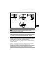
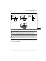
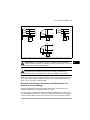
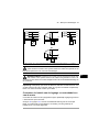
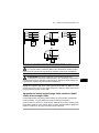
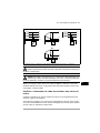
Check the compatibility with IT (ungrounded), corner-
grounded delta, midpoint-grounded delta and TT systems
The standard drive with ground-to-phase varistors connected can be installed to a
symmetrically grounded TN-S system. For other systems, see the hardware manual
and ACS880 frames R1 to R11 EMC filter and ground-to-phase varistor
disconnecting instructions (3AUA0000125152 [English]).

EN – Quick installation guide 5
EN
DA
DE
ES
FI
FR
IT
NL
PT
RU
SV
TR
CN
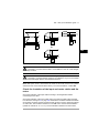
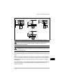
.
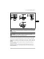
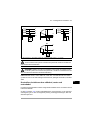
A = TN-S system, B1 = Corner-grounded system, B2 = Midpoint-grounded system, C = IT system
WARNING! Do not install the drive with EMC filter options +E200 and +E202
connected to a system that the filter is not suitable for. This can cause danger,
or damage the drive.
WARNING! Do not install the drive with the ground-to-phase varistor
connected to a system that the varistor is not suitable for. If you do, the varistor
circuit can be damaged. See the drive hardware manual.
Note: With option +E201, remove EMC AC, EMC DC and VAR screws in for systems
other than TN-S if not removed at the factory. For more information, contact ABB.
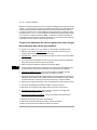
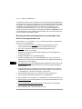
Check the insulation of the input and motor cables and the
motor
Check the insulation of the input cable according to local regulations before you
connect it to the drive.
See figure D on page 103. Ground the motor cable shield at the motor end. For
minimal interference, make a 360-degree grounding at the cable lead-through, or
keep the pig tail short.
PE
N
L3
L2
L1
PE
L3
L2
L1
L3
L2
L1
PE
L3
L2
L1
B1 CA
B2

6 EN – Quick installation guide
EN
DA
DE
ES
FI
FR
IT
NL
PT
RU
SV
TR
CN
Check the insulation of the motor cable and motor when the cable is disconnected
from the drive, see figure E on page 103. Measure the insulation resistance between
each phase conductor and the Protective Earth conductor using a measuring voltage
of 1000 V DC. The insulation resistance of an ABB motor must exceed 100 Mohm
(reference value at 25 °C or 77 °F). For the insulation resistance of other motors,
please consult the manufacturer’s instructions. Note: Moisture inside the motor
casing will reduce the insulation resistance. If moisture is suspected, dry the motor
and repeat the measurement.
Attach the warning stickers in local languages
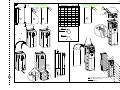
Connect the power cables
See figures C and F on pages 102 and 103. Use symmetrical shielded cable for the
motor cabling.
1. Remove the front cover. IP21 units
: Release the retaining clip with a screwdriver
(a) and lift the cover from the bottom outwards (b).
2. IP21 units
: Remove the cable entry box cover by undoing the mounting screws.
3. Attach the residual voltage warning sticker in the local language next to the
control unit.
4. Remove the side plates of the cable entry box.
5. Remove the shroud on the power cable terminals by releasing the clips on the
sides with a screwdriver and lifting (a). Knock out holes for the cables (b).
6. For frames R8 and R9:
If parallel cables are installed, knock out the shrouds on
the power cable terminals for the cables to be installed.
7. Cut adequate holes into the rubber grommets. Slide the grommets onto the
cables. Prepare the cable ends. Slide the cables through the holes of the bottom
plate and attach the grommets to the holes.
8. Ground the cable shields 360 degrees under the grounding clamps.
9. Connect the twisted cable shields to the grounding terminals.
10. Connect the conductors of the input and motor cables. Tighten the screws.
11. Units with option +D150:
Connect the conductors of the brake resistor cable to the
R+ and R- terminals.
12. If parallel cables are installed
, install the grounding shelf for them. Repeat steps 7
to 12.
13. Reinstall the shroud on the power terminals.
14. Reinstall the side plates of the cable entry box.
15. Secure the cables outside the unit mechanically.

EN – Quick installation guide 7
EN
DA
DE
ES
FI
FR
IT
NL
PT
RU
SV
TR
CN
Connect the control cables
See figure G.
1. Install the control cable grounding shelf in the cable entry box.
2. Cut adequate holes into the rubber grommets and slide the grommets onto the
cables. Slide the cables through the holes of the bottom plate and attach the
grommets to the holes.
3. Strip the cable ends and cut to suitable length (note the extra length of the
grounding conductors).
4. Ground the outer shields of all control cables 360 degrees at a grounding clamp in
the cable entry box.
5. Ground the pair-cable shields to a grounding clamp below the control board.
Leave the other end of the shields unconnected or ground them indirectly via a
high-frequency capacitor with a few nanofarads, eg, 3.3 nF / 630 V.
6. Connect the conductors to the appropriate terminals of the control board (see
page 8).
7. Wire the optional modules if included in the delivery.
8. Reinstall the front cover.
Note for fieldbus cabling. See figure H.
1. Install the additional grounding shelf.
2. Ground the outer shields of the cables 360 degrees at a grounding clamp.
3. Knock out holes in the cable entry box cover for the cables to be installed. Install
the cable entry box cover.
4. Plug the connector to the fieldbus module.
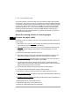
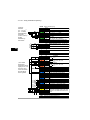
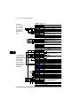
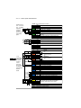
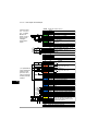
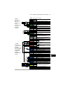
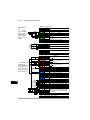
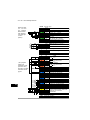
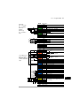
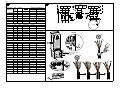
Default I/O connections
The default I/O connections of the Factory macro of the ACS880 primary control
program are shown below.

8 EN – Quick installation guide
EN
DA
DE
ES
FI
FR
IT
NL
PT
RU
SV
TR
CN
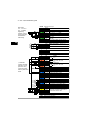
XPOW External power input
1 +24VI
24 V DC, 2 A
2 GND
XAI Reference voltage and analog inputs
1 +VREF 10 V DC, R
L
1…10 kohm
2 -VREF -10 V DC, R
L
1…10 kohm
3 AGND Ground
4 AI1+ Speed reference 0(2)…10 V, R
in
>
200 kohm
5 AI1-
6 AI2+
By default not in use. 0(4)…20 mA, R
in
=
100 ohm
7 AI2-
J1 J1 AI1 current/voltage selection jumper
J2 J2 AI2 current/voltage selection jumper
XAO Analog outputs
1 AO1 Motor speed rpm 0…20 mA, R
L
<
500 ohm
2 AGND
3 AO2
Motor current 0…20 mA, R
L
< 500 ohm
4 AGND
XD2D Drive-to-drive link
1 B
Drive-to-drive link
2 A
3 BGND
J3 J3 Drive-to-drive link termination switch
XRO1, XRO2, XRO3 Relay outputs
11 NC
Ready
250 V AC / 30 V DC
2 A
12 COM
13 NO
21 NC
Running
250 V AC / 30 V DC
2 A
22 COM
23 NO
31 NC
Faulted(-1)
250 V AC / 30 V DC
2 A
32 COM
33 NO
XD24 Digital interlock
1 DIIL Run enable
2 +24VD +24 V DC 200 mA
1)
3 DICOM Digital input ground
4 +24VD +24 V DC 200 mA
1)
5 DIOGND Digital input/output ground
J6 Ground selection switch
XDIO Digital input/outputs
1 DIO1 Output: Ready
2 DIO2 Output: Running
XDI Digital inputs
1 DI1 Stop (0) / Start (1)
2 DI2 Forward (0) / Reverse (1)
3 DI3 Reset
4 DI4 Acceleration & deceleration select
5 DI5 Constant speed 1 (1 = On)
6 DI6 By default not in use.
XSTO Safe torque off
1 OUT1
Safe torque off. Both circuits must be
closed for the drive to start.
2 SGND
3 IN1
4 IN2
X12 Safety functions module connection
X13 Control panel connection
X205 Memory unit connection
Wire sizes:
0.5 … 2.5 mm
2
(24…12 AWG)
Tightening
torques: 0.5 N·m
(5 lbf·in) for both
stranded and
solid wiring.
1)
Total load
capacity of these
outputs is 4.8 W
(200 mA / 24 V)
minus the power
taken by DIO1 and
DIO2.
Fault

EN – USA quick installation guide 9
DA
USA
DA
DE
ES
FI
FR
IT
NL
PT
RU
SV
TR
CN
EN – USA quick installation guide
This guide instructs briefly how to install the drive. For more detailed instructions,
engineering guide lines, technical data and complete safety instructions, see the
hardware manual (www.abb.com/drives
: Select Document Library and search for
document number 3AUA0000078093 [English]).
Obey the safety instructions
The floor material below the drive must be non-flammable.
Check if capacitors need to be reformed
Reform the capacitors if the drive has not been powered (either in storage or unused)
for a year or more.
You can determine the manufacturing date from the serial number, which you find on
the type designation label attached to the drive. The serial number is of format
MYYWWRXXXX. YY and WW tell the manufacturing year and week as follows:
YY: 17, 18, 19, … for 2017, 2018, 2019,
…
WW: 01, 02, 03, … for week 1, week 2, week 3, …
For information on reforming the capacitors, see Converter modules with
electrolytic DC capacitors in the DC link capacitor reforming instructions
WARNING! Obey these instructions. If you ignore them, injury or death, or
damage to the equipment can occur:
• Only qualified electrical professionals are allowed to install and maintain the
drive.
• Never work on the drive, motor cable or motor when main power is applied. If
the drive is already connected to the input power, wait for 5 minutes after
disconnecting the input power.
• Never work on the control cables when power is applied to the drive or to the
external control circuits.
• Always ground the drive, the motor and adjoining equipment to the protective
earth (PE) bus of the power supply.
• Make sure that debris from borings and grindings does not enter the drive when
installing.
• Do not connect the drive to a voltage higher than what is marked on the type
designation label.

10 EN – USA quick installation guide
DA
USA
DA
DE
ES
FI
FR
IT
NL
PT
RU
SV
TR
CN
(3BFE64059629 [English]), available on the Internet at
www.abb.com/drives/documents.
Select the power cables
Size the power cables according to local regulations to carry the nominal current
given on the type designation label of your drive.
Typical power cable sizes are listed in table B on page 102. For the conditions of the
sizing, see the hardware manual.
Ensure the cooling
See table A on page 105 for the losses and the cooling air flow through the drive. The
allowed operating temperature range of the drive without derating is -15 to +40 °C.
Protect the drive and input power cable
See table A on page 105 for the UL class T fuses for branch circuit protection per
NEC. Check that the operating time of the fuse is below 0.5 seconds for frame R6
and below 0.1 seconds for frames R7 to R9. Obey local regulations.
Install the drive on the wall
See figure A on page 101. For UL Type 12 drives: Install also the hood to the drive.
Check the compatibility with IT (ungrounded), corner-
grounded delta, midpoint-grounded delta and TT systems
The standard drive with ground-to-phase varistors connected can be installed to a
symmetrically grounded TN-S system. For other systems, see the hardware manual
and ACS880 frames R1 to R11 EMC filter and ground-to-phase varistor
disconnecting instructions (3AUA0000125152 [English]).

EN – USA quick installation guide 11
DA
USA
DA
DE
ES
FI
FR
IT
NL
PT
RU
SV
TR
CN
A = TN-S system, B1 = Corner-grounded system, B2 = Midpoint-grounded system, C = IT system
WARNING! Do not install the drive with EMC filter options +E200 and +E202
connected to a system that the filter is not suitable for. This can cause danger,
or damage the drive.
WARNING! Do not install the drive with the ground-to-phase varistor
connected to a system that the varistor is not suitable for. If you do, the varistor
circuit can be damaged. See the drive hardware manual.
Note: With option +E201, remove EMC AC, EMC DC and VAR screws in for systems
other than TN-S if not removed at the factory. For more information, contact ABB.
Check the insulation of the input and motor cables and the
motor
Check the insulation of the input cable according to local regulations before
connecting it to the drive.
Check the insulation of the motor cable and motor when the cable is disconnected
from the drive, see figure D on page 105. Measure the insulation resistance between
each phase conductor and the Protective Earth conductor using a measuring voltage
of 1000 V DC. The insulation resistance of an ABB motor must exceed 100 Mohm
(reference value at 25 °C or 77 °F). For the insulation resistance of other motors,
PE
L3
L2
L1
L3
L2
L1
PE
L3
L2
L1
B1 C
B2
PE
L2
L3
L1
N
A

12 EN – USA quick installation guide
DA
USA
DA
DE
ES
FI
FR
IT
NL
PT
RU
SV
TR
CN
please consult the manufacturer’s instructions. Note: Moisture inside the motor
casing will reduce the insulation resistance. If moisture is suspected, dry the motor
and repeat the measurement.
Connect the power cables
See figures B, C and E on pages 105 and 106. Use symmetrical shielded cable for
the motor cabling.
1. Remove the front cover. UL Type 1 drives:
Release the retaining clip with a
screwdriver (a) and lift the cover from the bottom outwards (b).
2. UL Type 1 drives:
Remove the cable entry box cover by undoing the mounting
screws.
3. Attach the residual voltage warning sticker in the local language next to the
control board top.
4. Remove the side plates of the cable entry box.
5. Remove the shroud on the power cable terminals by releasing the clips on the
sides with a screwdriver and lifting (a). If parallel cables are installed
, knock out
holes for the cables (b).
6. Knock out the shrouds on the power cable terminals for the cables to be installed.
7. Fasten the cable conduits to the cable lead-through plate holes. Strip the cable
ends. Slide the cables through the connectors.
8. Connect the twisted cable shields to the grounding terminals.
9. Connect the conductors of the input and motor cables. Tighten the screws.
10. Units with option +D150:
Connect the conductors of the brake resistor cable to the
R+ and R- terminals.
11. Reinstall the shroud on the power terminals.
12. Reinstall the side plates of the cable entry box.
13. Secure the cables outside the unit mechanically.
Connect the control cables
Install the control cable grounding shelf in the cable entry box (see figure F on page
106).
See figure G on page 106.

EN – USA quick installation guide 13
DA
USA
DA
DE
ES
FI
FR
IT
NL
PT
RU
SV
TR
CN
1. Fasten the cable conduits to the cable lead-through plate holes. Slide the cables
through the connectors.
2. Strip the cable ends and cut to suitable length (note the extra length of the
grounding conductors).
3. Ground the outer shields of all control cables 360 degrees at a grounding clamp in
the cable entry box.
4. Ground the pair-cable shields to a grounding clamp below the control board.
Leave the other end of the shields unconnected or ground them indirectly via a
high-frequency capacitor with a few nanofarads, eg, 3.3 nF / 630 V.
5. Connect the conductors to the appropriate terminals of the control board (see
page 14).
6. Wire the optional modules if included in the delivery. For fieldbus modules, see
figure H on page 104
7. Reinstall the front covers.
Default I/O connections
The default I/O connections of the Factory macro of the ACS880 primary control
program are shown below.

14 EN – USA quick installation guide
DA
USA
DA
DE
ES
FI
FR
IT
NL
PT
RU
SV
TR
CN
XPOW External power input
1 +24VI
24 V DC, 2 A
2 GND
XAI Reference voltage and analog inputs
1 +VREF 10 V DC, R
L
1…10 kohm
2 -VREF -10 V DC, R
L
1…10 kohm
3 AGND Ground
4 AI1+ Speed reference 0(2)…10 V, R
in
>
200 kohm
5 AI1-
6 AI2+
By default not in use. 0(4)…20 mA, R
in
=
100 ohm
7 AI2-
J1 J1 AI1 current/voltage selection jumper
J2 J2 AI2 current/voltage selection jumper
XAO Analog outputs
1 AO1 Motor speed rpm 0…20 mA, R
L
<
500 ohm
2 AGND
3 AO2
Motor current 0…20 mA, R
L
< 500 ohm
4 AGND
XD2D Drive-to-drive link
1 B
Drive-to-drive link
2 A
3 BGND
J3 J3 Drive-to-drive link termination switch
XRO1, XRO2, XRO3 Relay outputs
1 NC
Ready
250 V AC / 30 V DC
2 A
2 COM
3 NO
1 NC
Running
250 V AC / 30 V DC
2 A
2 COM
3 NO
1 NC
Faulted(-1)
250 V AC / 30 V DC
2 A
2 COM
3 NO
XD24 Digital interlock
1 DIIL Run enable
2 +24VD +24 V DC 200 mA
1)
3 DICOM Digital input ground
4 +24VD +24 V DC 200 mA
1)
5 DIOGND Digital input/output ground
J6 Ground selection switch
XDIO Digital input/outputs
1 DIO1 Output: Ready
2 DIO2 Output: Running
XDI Digital inputs
1 DI1 Stop (0) / Start (1)
2 DI2 Forward (0) / Reverse (1)
3 DI3 Reset
4 DI4 Acceleration & deceleration select
5 DI5 Constant speed 1 (1 = On)
6 DI6 By default not in use.
XSTO Safe torque off
1 OUT1
Safe torque off. Both circuits must be
closed for the drive to start.
2 SGND
3 IN1
4 IN2
X12 Safety functions module connection
X13 Control panel connection
X205 Memory unit connection
Wire sizes:
0.5 … 2.5 mm
2
(24…12 AWG)
Tightening
torques: 0.5 N·m
(5 lbf·in) for both
stranded and
solid wiring.
1)
Total load
capacity of these
outputs is 4.8 W
(200 mA / 24 V)
minus the power
taken by DIO1 and
DIO2.
Fault

EN – USA quick installation guide 15
DA
USA
DA
DE
ES
FI
FR
IT
NL
PT
RU
SV
TR
CN
UL checklist
• Use the drive in a heated, indoor controlled environment. The drive must be
installed in clean air according to enclosure classification. Cooling air must be
clean, free from corrosive materials and electrically conductive dust.
• The maximum ambient air temperature is 40 °C (104 °F) at rated current. The
current is derated for 40 to 55 °C (104 to 131 °F).
• The drive is suitable for use in a circuit capable of delivering not more than
100,000 rms symmetrical amperes, 600 V maximum. The ampere rating is based
on tests done according to UL 508C.
• The cables located within the motor circuit must be rated for at least 75 °C
(167 °F) in UL-compliant installations.
• The input cable must be protected with fuses. Circuit breakers must not be used
without fuses in the USA. Suitable IEC (class aR) fuses and UL (class T) fuses
are listed in the hardware manual. For suitable circuit breakers, contact your local
ABB representative.
• For installation in the United States, branch circuit protection must be provided in
accordance with the National Electrical Code (NEC) and any applicable local
codes. To fulfill this requirement, use the UL classified fuses.
• For installation in Canada, branch circuit protection must be provided in
accordance with the Canadian Electrical Code and any applicable provincial
codes. To fulfill this requirement, use the UL classified fuses.
• The drive provides overload protection in accordance with the National Electrical
Code (NEC).

16 EN – USA quick installation guide
DA
USA
DA
DE
ES
FI
FR
IT
NL
PT
RU
SV
TR
CN

DA – Hurtig installationsvejledning 17
EN
DA
DA
ES
FI
FR
IT
NL
PT
RU
SV
TR
CN
DA – Hurtig installationsvejledning
Denne guide er en kortfattet vejledning i, hvordan du installerer frekvensomformeren.
Hvis du vil have mere detaljerede instruktioner, tekniske retningslinjer, tekniske data
og komplette sikkerhedsinstruktioner, kan du se hardwaremanualen
(www.abb.com/drives
: Vælg Document Library, og søg efter dokumentnummer
3AUA0000078093 (på engelsk).
Overhold sikkerhedsinstruktionerne
Gulvmaterialet under frekvensomformeren skal være ikke-brandbart.
Kontrollér, om det er nødvendigt at reformere
kondensatorerne
Reformér kondensatorerne, hvis frekvensomformeren ikke har været tilsluttet strøm i
over et år (opbevaret eller ikke anvendt).
Du kan bestemme produktionsdatoen ud fra serienummeret, som du finder på
mærkatet med typebetegnelse på frekvensomformeren. Serienummeret har formatet
MYYWWRXXXX. YY og WW angiver produktionsåret og ugen på følgende måde:
YY: 17, 18, 19, … for 2017, 2018, 2019,
…
WW: 01, 02, 03, … for uge 1, uge 2, uge 3, …
ADVARSEL! Følg disse instruktioner. Hvis de ignoreres, kan det resultere i
personskader, dødsfald eller skade på udstyret:
• Kun autoriserede elinstallatører må udføre installation og vedligeholdelse af
frekvensomformeren.
• Undlad at arbejde med frekvensomformeren, motorkablet eller motoren, når
tilslutning til nettet er foretaget. Hvis frekvensomformeren allerede er tilsluttet
netforsyningen, skal du vente 5 minutter efter frakobling af netspændingen.
• Du må aldrig arbejde med signalkablerne, når netspændingen er tilsluttet
frekvensomformeren eller de eksterne styrekredse.
• Frekvensomformeren, motoren og tilstødende udstyr skal altid jordes med
strømforsyningens beskyttelsesjordbus (PE).
• Undgå, at der trænger smuds fra boringer og sliberester ind i
frekvensomformeren under installation.
• Frekvensomformeren må ikke tilsluttes til en spænding, der er højere end den,
der er angivet på mærkatet med typebetegnelse.

18 DA – Hurtig installationsvejledning
EN
DA
DA
ES
FI
FR
IT
NL
PT
RU
SV
TR
CN
Oplysninger om reformering af kondensatorer findes i Converter modules with
electrolytic DC capacitors in the DC link capacitor reforming instructions
(3BFE64059629 (på engelsk)), som findes på internettet på
www.abb.com/drives/documents
.
Vælg effektkabler
Vælg en størrelse til kablerne i henhold til lokale forskrifter til at bære den nominelle
strøm, der er anført på mærkatet med typebetegnelsen på din frekvensomformer.
Typiske størrelser på netkabler er vist i tabellen B på side 102. Se hardwaremanualen
for oplysninger om betingelserne for størrelse.
Sørg for kølingen
Se tabel B på side 102 for tabene og frekvensomformerens gennemstrømning af
kølende luft. Frekvensomformerens tilladte driftstemperaturområde uden reduktion er
-15 til +40 °C.
Beskyt frekvensomformeren og forsyningskablet
Se tabellen B på side 102.
Installer frekvensomformeren på væggen
Se figur A på side 101.
Kontrollér kompatibiliteten med IT-net (ujordede),
hjørnejordede delta-, midtpunktsjordet delta- og
TT-systemer
Standardfrekvensomformeren med tilsluttet jord-til-fase-varistorer kan installeres
sammen med et symmetrisk jordet TN-S-system. Oplysninger om andre systemer
finder du i hardwaremanualen samt i ACS880 frames R1 to R11 EMC filter and ground-
to-phase varistor disconnecting instructions (3AUA0000125152 (på engelsk)).

DA – Hurtig installationsvejledning 19
EN
DA
DA
ES
FI
FR
IT
NL
PT
RU
SV
TR
CN
A = TN-S-system, B1 = Hjørnejordet system, B2 = Midtpunktsjordet system, C = IT-system
ADVARSEL! Installer ikke en frekvensomformer med tilsluttet EMC-filter
ekstraudstyr +E200 og +E202 til et system, hvortil filtret ikke er egnet. Dette
kan medføre fare eller ødelægge frekvensomformeren.
ADVARSEL! Installer ikke frekvensomformeren med tilsluttet jord-til-fase-
varistor til et system, hvortil varistoren ikke er egnet. Hvis du gør det, kan
varistorkredsløbet tage skade. Se frekvensomformerens hardwaremanual.
Bemærk! Hvis du anvender ekstraudstyr +E201, skal du fjerne EMC AC-, EMC DC-
og VAR-skruerne i andre systemer end TN-S, hvis de ikke allerede er fjernet på
fabrikken. Kontakt ABB for at få yderligere oplysninger.
Kontroller isoleringen på forsynings- og motorkabel samt
motoren
Kontrollér, at isoleringen af forsyningskablet er i overensstemmelse med de nationale
forskrifter, inden du tilslutter det til frekvensomformeren.
Se figur D på side 103. Tilslut motorkablets skærm i motoren. Opnå minimal
interferens ved at lave en 360 graders jording ved kabelgennemføringen eller holde
den snoede kobberskærm kort.
PE
N
L3
L2
L1
PE
L3
L2
L1
L3
L2
L1
PE
L3
L2
L1
B1 CA
B2

20 DA – Hurtig installationsvejledning
EN
DA
DA
ES
FI
FR
IT
NL
PT
RU
SV
TR
CN
Kontrollér isoleringen af motorkabel og motor, når kablet er koblet fra
frekvensomformeren. Se figur E på side 103. Mål isolationsmodstanden mellem hver
faseleder og beskyttelsesjordens leder med en målespænding på 1000 V DC.
Isolationsmodstanden på en ABB-motor skal være større end 100 Mohm
(referenceværdi ved 25 °C eller 77 °F). Se producentens instruktioner for at få
oplysninger om isolationsmodstanden på andre motorer. Bemærk! Fugt inden i
motorhuset reducerer isolationsmodstanden. Hvis der er mistanke om fugt, skal
motoren tørres, og målingen gentages.
Fastgør advarselsmærkaterne på de lokale sprog
Tilslut effektkablerne
Se figurerne C og F på siderne 102 og 103. Anvend et skærmet symmetrisk kabel til
motoren.
1. Fjern frontdækslet. IP21-enheder
: Løsn låsesplitten med en skruetrækker (a), og
løft dækslet udad fra bunden (b).
2. IP21-enheder
: Fjern dæksel for kabelsektion ved at løsne monteringsskruerne.
3. Fastgør advarselsmærkatet om restspænding på det lokale sprog ved siden af
styreenheden.
4. Fjern sidepladerne fra kabelindgangskassen.
5. Fjern afdækningen for effektkablernes terminaler ved at frigøre splitterne og løfte
afdækningen op fra siderne med en skruetrækker (a). Slå hullerne ud, hvor
kablerne skal installeres (b).
6. Til modulerne R8 og R9:
Hvis der er installeret parallelkabler, skal du slå
afskærmningerne ud på effektkabelterminalerne til de kabler, som skal installeres.
7. Skær tilstrækkeligt store huller i gummimufferne. Træk mufferne over på kablerne.
Forbered kabelenderne. Før kablerne gennem hullerne på bundpladen, og sæt
mufferne fast i hullerne.
8. Jord kabelskærmene 360 grader under jordingsklemmerne.
9. Tilslut de snoede kabelskærme til jordterminaler.
10. Forbind faselederne på forsynings- og motorterminalerne. Stram skruerne.
11. Enheder med ekstraudstyr +D150:
Forbind lederne i modstandskablet til
terminalerne R+ og R-.
12. Hvis der monteres parallelle kabler
, monteres jordingsplint til dem. Gentag trin 7-12.
13. Genmontér afskærmningen på effektterminalerne.
14. Montér sidepladerne på kabelsektionen.
15. Fastgør kablerne mekanisk uden for frekvensomformeren.
Sayfa yükleniyor ...
Sayfa yükleniyor ...
Sayfa yükleniyor ...
Sayfa yükleniyor ...
Sayfa yükleniyor ...
Sayfa yükleniyor ...
Sayfa yükleniyor ...
Sayfa yükleniyor ...
Sayfa yükleniyor ...
Sayfa yükleniyor ...
Sayfa yükleniyor ...
Sayfa yükleniyor ...
Sayfa yükleniyor ...
Sayfa yükleniyor ...
Sayfa yükleniyor ...
Sayfa yükleniyor ...
Sayfa yükleniyor ...
Sayfa yükleniyor ...
Sayfa yükleniyor ...
Sayfa yükleniyor ...
Sayfa yükleniyor ...
Sayfa yükleniyor ...
Sayfa yükleniyor ...
Sayfa yükleniyor ...
Sayfa yükleniyor ...
Sayfa yükleniyor ...
Sayfa yükleniyor ...
Sayfa yükleniyor ...
Sayfa yükleniyor ...
Sayfa yükleniyor ...
Sayfa yükleniyor ...
Sayfa yükleniyor ...
Sayfa yükleniyor ...
Sayfa yükleniyor ...
Sayfa yükleniyor ...
Sayfa yükleniyor ...
Sayfa yükleniyor ...
Sayfa yükleniyor ...
Sayfa yükleniyor ...
Sayfa yükleniyor ...
Sayfa yükleniyor ...
Sayfa yükleniyor ...
Sayfa yükleniyor ...
Sayfa yükleniyor ...
Sayfa yükleniyor ...
Sayfa yükleniyor ...
Sayfa yükleniyor ...
Sayfa yükleniyor ...
Sayfa yükleniyor ...
Sayfa yükleniyor ...
Sayfa yükleniyor ...
Sayfa yükleniyor ...
Sayfa yükleniyor ...
Sayfa yükleniyor ...
Sayfa yükleniyor ...
Sayfa yükleniyor ...
Sayfa yükleniyor ...
Sayfa yükleniyor ...
Sayfa yükleniyor ...
Sayfa yükleniyor ...
Sayfa yükleniyor ...
Sayfa yükleniyor ...
Sayfa yükleniyor ...
Sayfa yükleniyor ...
Sayfa yükleniyor ...
Sayfa yükleniyor ...
Sayfa yükleniyor ...
Sayfa yükleniyor ...
Sayfa yükleniyor ...
Sayfa yükleniyor ...
Sayfa yükleniyor ...
Sayfa yükleniyor ...
Sayfa yükleniyor ...
Sayfa yükleniyor ...
Sayfa yükleniyor ...
Sayfa yükleniyor ...
Sayfa yükleniyor ...
Sayfa yükleniyor ...
Sayfa yükleniyor ...
Sayfa yükleniyor ...
Sayfa yükleniyor ...
Sayfa yükleniyor ...
Sayfa yükleniyor ...
Sayfa yükleniyor ...
Sayfa yükleniyor ...
Sayfa yükleniyor ...
Sayfa yükleniyor ...
Sayfa yükleniyor ...
-
 1
1
-
 2
2
-
 3
3
-
 4
4
-
 5
5
-
 6
6
-
 7
7
-
 8
8
-
 9
9
-
 10
10
-
 11
11
-
 12
12
-
 13
13
-
 14
14
-
 15
15
-
 16
16
-
 17
17
-
 18
18
-
 19
19
-
 20
20
-
 21
21
-
 22
22
-
 23
23
-
 24
24
-
 25
25
-
 26
26
-
 27
27
-
 28
28
-
 29
29
-
 30
30
-
 31
31
-
 32
32
-
 33
33
-
 34
34
-
 35
35
-
 36
36
-
 37
37
-
 38
38
-
 39
39
-
 40
40
-
 41
41
-
 42
42
-
 43
43
-
 44
44
-
 45
45
-
 46
46
-
 47
47
-
 48
48
-
 49
49
-
 50
50
-
 51
51
-
 52
52
-
 53
53
-
 54
54
-
 55
55
-
 56
56
-
 57
57
-
 58
58
-
 59
59
-
 60
60
-
 61
61
-
 62
62
-
 63
63
-
 64
64
-
 65
65
-
 66
66
-
 67
67
-
 68
68
-
 69
69
-
 70
70
-
 71
71
-
 72
72
-
 73
73
-
 74
74
-
 75
75
-
 76
76
-
 77
77
-
 78
78
-
 79
79
-
 80
80
-
 81
81
-
 82
82
-
 83
83
-
 84
84
-
 85
85
-
 86
86
-
 87
87
-
 88
88
-
 89
89
-
 90
90
-
 91
91
-
 92
92
-
 93
93
-
 94
94
-
 95
95
-
 96
96
-
 97
97
-
 98
98
-
 99
99
-
 100
100
-
 101
101
-
 102
102
-
 103
103
-
 104
104
-
 105
105
-
 106
106
-
 107
107
-
 108
108


ABB ACS880-01 Series Quick Installation Manual
- Tip
- Quick Installation Manual
Diğer dillerde
- español: ABB ACS880-01 Series
- français: ABB ACS880-01 Series
- italiano: ABB ACS880-01 Series
- svenska: ABB ACS880-01 Series
- polski: ABB ACS880-01 Series
- Deutsch: ABB ACS880-01 Series
- português: ABB ACS880-01 Series
- English: ABB ACS880-01 Series
- dansk: ABB ACS880-01 Series
- русский: ABB ACS880-01 Series
- suomi: ABB ACS880-01 Series
- Nederlands: ABB ACS880-01 Series
İlgili Makaleler
-
ABB ACS880-01 Series Quick Installation Manual
-
-
-
ABB ACH580-01-07A3-4 Quick Installation And Start-Up Manual
-
ABB ACS580-05 Quick Installation And Setup Manual
-
-
ABB ACS850-04 series Quick Installation Manual
-
-
-
ABB ACS880 Series Quick Start Up Manual