ABB ACS880-01-09A8-7 Quick Installation Manual
- Tip
- Quick Installation Manual

English. . . . . . . . 3
English – USA . . 9
Dansk . . . . . . . 15
Deutsch . . . . . . 21
Español . . . . . . 27
Suomi . . . . . . . 33
Français. . . . . . 39
Italiano. . . . . . . 45
Nederlands . . . 51
Polski. . . . . . . . 57
Português . . . . 63
. . . . . 69
Svenska. . . . . . 75
Türkçe . . . . . . . 81
中文 . . . . . . . . .
87
EN
USA
DA
DE
ES
FI
FR
IT
NL
PL
PT
RU
SV
TR
ZH
ABB industrial drives
Quick installation guide
ACS880-01 drives
Frames R6 to R9

List of related manuals
You can find manuals and other product documents in PDF format on the Internet. See section
Document library on the Internet on the inside of the back cover. For manuals not available in the
Document library, contact your local ABB representative.
The QR code below opens an online listing of the manuals applicable to this product.
ACS880-01 manuals
Drive hardware manuals and guides Code (English)
ACS880-01 hardware manual 3AUA0000078093
ACS880-01 quick installation guide for frames R1 to R3 3AUA0000085966
ACS880-01 quick installation guide for frames R4 and R5 3AUA0000099663
ACS880-01 quick installation guide for frames R6 to R9 3AUA0000099689
ACS880-01 +P940 drives for cabinet installation
supplement
3AUA0000145446
ACS880-01 assembly drawings for cable entry boxes of
IP21 frames R5 to R9
3AUA0000119627
ACS-AP-x assistant control panels user’s manual 3AUA0000085685
Vibration dampers for ACS880-01 drives (frames R4 and
R5, option +C131) installation guide
3AXD50000010497
Vibration dampers for ACS880-01 drives (frames R6 to
R9, option +C131) installation guide
3AXD50000013389
ACS880-01 +C132 marine type-approved drives
supplement
3AXD50000010521
Drive firmware manuals and guides
ACS880 primary control program firmware manual 3AUA0000085967
Quick start-up guide for ACS880 drives with primary
control program
3AUA0000098062
Option manuals and guides
Manuals and quick guides for I/O extension modules,
fieldbus adapters, etc.
3AUA0000099689 Rev E
MUL
EFFECTIVE: 2014-08-13
2014 ABB Oy. All Rights Reserved.

EN – Quick installation guide 3
EN
DA
DE
ES
FI
FR
IT
NL
PT
RU
SV
TR
CN
EN – Quick installation guide
This guide instructs briefly how to install the drive. For more detailed instructions,
engineering guide lines, technical data and complete safety instructions, see the
hardware manual (www.abb.com/drives
: Select Document Library and search for
document number 3AUA0000099689 [English]).
Obey the safety instructions
The floor material below the drive must be non-flammable.
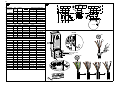
Select the power cables
Size the power cables according to local regulations to carry the nominal current
given on the type designation label of your drive.
Typical power cable sizes are listed in table B on page 92. For the conditions of the
sizing, see the hardware manual.
Ensure the cooling
See table B on page 92 for the losses and the cooling air flow through the drive. The
allowed operating temperature range of the drive without derating is -15 to +40 °C.
Protect the drive and input power cables
See table B on page 92.
WARNING! Ignoring the following instructions can cause physical injury or
death, or damage to the equipment:
• Only qualified electricians are allowed to install and maintain the drive.
• Never work on the drive, motor cable or motor when main power is applied.
After disconnecting the input power, always wait for 5 min to let the intermediate
circuit capacitors discharge before you start working on the drive, motor or
motor cable.
• Do not work on the control cables when power is applied to the drive or to the
external control circuits.
• Make sure that debris from borings and grindings does not enter the drive when
installing.
• Do not connect the drive to a voltage higher than what is marked on the type
designation label.

4 EN – Quick installation guide
EN
DA
DE
ES
FI
FR
IT
NL
PT
RU
SV
TR
CN
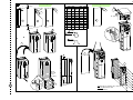
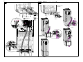
Install the drive on the wall
See figure A on page 91.
Check the insulation of the input and motor cables and the
motor
Check the insulation of the input cable according to local regulations before
connecting it to the drive.
See figure D on page 93. Ground the motor cable shield at the motor end. For
minimal interference, make a 360-degree grounding at the cable lead-through, or
keep the pig tail short.
Check the insulation of the motor cable and motor when the cable is disconnected
from the drive, see figure E on page 93. Measure the insulation resistance between
each phase conductor and the Protective Earth conductor using a measuring voltage
of 1000 V DC. The insulation resistance of an ABB motor must exceed 100 Mohm
(reference value at 25 °C or 77 °F). For the insulation resistance of other motors,
please consult the manufacturer’s instructions. Note: Moisture inside the motor
casing will reduce the insulation resistance. If moisture is suspected, dry the motor
and repeat the measurement.
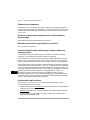
Connect the power cables
See figures C and F on pages 92 and 93. Use symmetrical shielded cable for the
motor cabling.
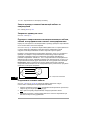
1. Remove the front cover. IP21 units
: Release the retaining clip with a screwdriver
(a) and lift the cover from the bottom outwards (b).
2. IP21 units
: Remove the cable entry box cover by undoing the mounting screws.
3. Attach the residual voltage warning sticker in the local language next to the
control unit.
4. Remove the side plates of the cable entry box.
5. Remove the shroud on the power cable terminals by releasing the clips on the
sides with a screwdriver and lifting (a). Knock out holes for the cables (b).
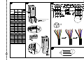
6. For frames R8 and R9: If parallel cables are installed, knock out the shrouds on
the power cable terminals for the cables to be installed.
7. Cut adequate holes into the rubber grommets. Slide the grommets onto the
cables. Prepare the cable ends. Slide the cables through the holes of the bottom
plate and attach the grommets to the holes.
8. Ground the cable shields 360 degrees under the grounding clamps.
9. Connect the twisted cable shields to the grounding terminals.

EN – Quick installation guide 5
EN
DA
DE
ES
FI
FR
IT
NL
PT
RU
SV
TR
CN
10. Connect the conductors of the input and motor cables. Tighten the screws.
11. Units with option +D150:
Connect the conductors of the brake resistor cable to the
R+ and R- terminals.
12. If parallel cables are installed
, install the grounding shelf for them. Repeat steps 7
to 12.
13. Reinstall the shroud on the power terminals.
14. Reinstall the side plates of the cable entry box.
15. Secure the cables outside the unit mechanically.
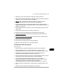
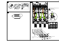
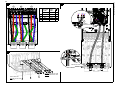
Connect the control cables
See figure G.
1. Install the control cable grounding shelf in the cable entry box.
2. Cut adequate holes into the rubber grommets and slide the grommets onto the
cables. Slide the cables through the holes of the bottom plate and attach the
grommets to the holes.
3. Strip the cable ends and cut to suitable length (note the extra length of the
grounding conductors).
4. Ground the outer shields of all control cables 360 degrees at a grounding clamp in
the cable entry box.
5. Ground the pair-cable shields to a grounding clamp below the control board.
Leave the other end of the shields unconnected or ground them indirectly via a
high-frequency capacitor with a few nanofarads, eg, 3.3 nF / 630 V.
6. Connect the conductors to the appropriate terminals of the control board (see
page 7).
7. Wire the optional modules if included in the delivery.
8. Reinstall the front cover.
Note for fieldbus cabling. See figure H.
1. Install the additional grounding shelf.
2. Ground the outer shields of the cables 360 degrees at a grounding clamp.
3. Knock out holes in the cable entry box cover for the cables to be installed. Install
the cable entry box cover.
4. Plug the connector to the fieldbus module.

6 EN – Quick installation guide
EN
DA
DE
ES
FI
FR
IT
NL
PT
RU
SV
TR
CN
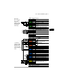
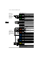
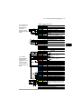
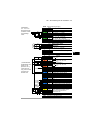
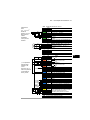
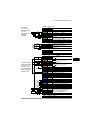
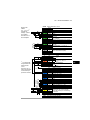
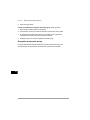
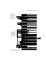
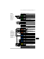
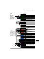
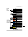
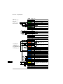
Default I/O connections
The default I/O connections of the Factory macro of the ACS880 primary control
program are shown below.

EN – Quick installation guide 7
EN
DA
DE
ES
FI
FR
IT
NL
PT
RU
SV
TR
CN
XPOW External power input
1 +24VI
24 V DC, 2 A
2 GND
XAI Reference voltage and analog inputs
1 +VREF 10 V DC, R
L
1…10 kohm
2 -VREF -10 V DC, R
L
1…10 kohm
3 AGND Ground
4 AI1+ Speed reference 0(2)…10 V, R
in
>
200 kohm
5 AI1-
6 AI2+
By default not in use. 0(4)…20 mA, R
in
=
100 ohm
7 AI2-
J1 J1 AI1 current/voltage selection jumper
J2 J2 AI2 current/voltage selection jumper
XAO Analog outputs
1 AO1 Motor speed rpm 0…20 mA, R
L
<
500 ohm
2 AGND
3 AO2
Motor current 0…20 mA, R
L
< 500 ohm
4 AGND
XD2D Drive-to-drive link
1 B
Drive-to-drive link
2 A
3 BGND
J3 J3 Drive-to-drive link termination switch
XRO1, XRO2, XRO3 Relay outputs
11 NC
Ready
250 V AC / 30 V DC
2 A
12 COM
13 NO
21 NC
Running
250 V AC / 30 V DC
2 A
22 COM
23 NO
31 NC
Faulted(-1)
250 V AC / 30 V DC
2 A
32 COM
33 NO
XD24 Digital interlock
1 DIIL Run enable
2 +24VD +24 V DC 200 mA
1)
3 DICOM Digital input ground
4 +24VD +24 V DC 200 mA
1)
5 DIOGND Digital input/output ground
J6 Ground selection switch
XDIO Digital input/outputs
1 DIO1 Output: Ready
2 DIO2 Output: Running
XDI Digital inputs
1 DI1 Stop (0) / Start (1)
2 DI2 Forward (0) / Reverse (1)
3 DI3 Reset
4 DI4 Acceleration & deceleration select
5 DI5 Constant speed 1 (1 = On)
6 DI6 By default not in use.
XSTO Safe torque off
1 OUT1
Safe torque off. Both circuits must be
closed for the drive to start.
2 SGND
3 IN1
4 IN2
X12 Safety functions module connection
X13 Control panel connection
X205 Memory unit connection
Wire sizes:
0.5 … 2.5 mm
2
(24…12 AWG)
Tightening
torques: 0.5 N·m
(5 lbf·in) for both
stranded and
solid wiring.
1)
Total load
capacity of these
outputs is 4.8 W
(200 mA / 24 V)
minus the power
taken by DIO1 and
DIO2.
Fault

8 EN – Quick installation guide
EN
DA
DE
ES
FI
FR
IT
NL
PT
RU
SV
TR
CN

EN – USA quick installation guide 9
DA
USA
DA
DE
ES
FI
FR
IT
NL
PT
RU
SV
TR
CN
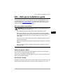
EN – USA quick installation guide
This guide instructs briefly how to install the drive. For more detailed instructions,
engineering guide lines, technical data and complete safety instructions, see the
hardware manual (www.abb.com/drives
: Select Document Library and search for
document number 3AUA0000099663 [English]).
Obey the safety instructions
The floor material below the drive must be non-flammable.
Select the power cables
Size the power cables according to local regulations to carry the nominal current
given on the type designation label of your drive.
Typical power cable sizes are listed in table B on page 92. For the conditions of the
sizing, see the hardware manual.
Ensure the cooling
See table A on page 95 for the losses and the cooling air flow through the drive. The
allowed operating temperature range of the drive without derating is -15 to +40 °C.
WARNING! Ignoring the following instructions can cause physical injury or
death, or damage to the equipment:
• Only qualified electricians are allowed to install and maintain the drive.
• Never work on the drive, motor cable or motor when main power is applied.
After disconnecting the input power, always wait for 5 min to let the intermediate
circuit capacitors discharge before you start working on the drive, motor or
motor cable.
• Do not work on the control cables when power is applied to the drive or to the
external control circuits.
• Make sure that debris from borings and grindings does not enter the drive when
installing.
• Do not connect the drive to a voltage higher than what is marked on the type
desgnation label.

10 EN – USA quick installation guide
DA
USA
DA
DE
ES
FI
FR
IT
NL
PT
RU
SV
TR
CN
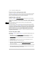
Protect the drive and input power cable
See table A on page 95 for the UL class T fuses for branch circuit protection per NEC.
Check that the operating time of the fuse is below 0.5 seconds for frame R6 and
below 0.1 seconds for frames R7 to R9. Obey local regulations.
Install the drive on the wall
See figure A on page 91. For UL TYpe 12 drives: Install also the hood to the drive.
Check the insulation of the input and motor cables and the
motor
Check the insulation of the input cable according to local regulations before
connecting it to the drive.
Check the insulation of the motor cable and motor when the cable is disconnected
from the drive, see figure D on page 95. Measure the insulation resistance between
each phase conductor and the Protective Earth conductor using a measuring voltage
of 1000 V DC. The insulation resistance of an ABB motor must exceed 100 Mohm
(reference value at 25 °C or 77 °F). For the insulation resistance of other motors,
please consult the manufacturer’s instructions. Note: Moisture inside the motor
casing will reduce the insulation resistance. If moisture is suspected, dry the motor
and repeat the measurement.
Connect the power cables
See figures B, C and E on pages 95 and 96. Use symmetrical shielded cable for the
motor cabling.
1. Remove the front cover. UL Type 1 drives:
Release the retaining clip with a
screwdriver (a) and lift the cover from the bottom outwards (b).
2. UL Type 1 drives:
Remove the cable entry box cover by undoing the mounting
screws.
3. Attach the residual voltage warning sticker in the local language next to the
control board top.
4. Remove the side plates of the cable entry box.
5. Remove the shroud on the power cable terminals by releasing the clips on the
sides with a screwdriver and lifting (a). If parallel cables are installed
, knock out
holes for the cables (b).
6. Knock out the shrouds on the power cable terminals for the cables to be installed.
7. Fasten the cable conduits to the cable lead-through plate holes. Strip the cable
ends. Slide the cables through the connectors.

EN – USA quick installation guide 11
DA
USA
DA
DE
ES
FI
FR
IT
NL
PT
RU
SV
TR
CN
8. Connect the twisted cable shields to the grounding terminals.
9. Connect the conductors of the input and motor cables. Tighten the screws.
10. Units with option +D150: Connect the conductors of the brake resistor cable to the
R+ and R- terminals.
11. Reinstall the shroud on the power terminals.
12. Reinstall the side plates of the cable entry box.
13. Secure the cables outside the unit mechanically.
Connect the control cables
Install the control cable grounding shelf in the cable entry box (see figure F on page
96).
See figure G on page 96.
1. Fasten the cable conduits to the cable lead-through plate holes. Slide the cables
through the connectors.
2. Strip the cable ends and cut to suitable length (note the extra length of the
grounding conductors).
3. Ground the outer shields of all control cables 360 degrees at a grounding clamp in
the cable entry box.
4. Ground the pair-cable shields to a grounding clamp below the control board.
Leave the other end of the shields unconnected or ground them indirectly via a
high-frequency capacitor with a few nanofarads, eg, 3.3 nF / 630 V.
5. Connect the conductors to the appropriate terminals of the control board (see
page 12).
6. Wire the optional modules if included in the delivery. For fieldbus modules, see
figure H on page 94
7. Reinstall the front covers.
Default I/O connections
The default I/O connections of the Factory macro of the ACS880 primary control
program are shown below.

12 EN – USA quick installation guide
DA
USA
DA
DE
ES
FI
FR
IT
NL
PT
RU
SV
TR
CN
XPOW External power input
1 +24VI
24 V DC, 2 A
2 GND
XAI Reference voltage and analog inputs
1 +VREF 10 V DC, R
L
1…10 kohm
2 -VREF -10 V DC, R
L
1…10 kohm
3 AGND Ground
4 AI1+ Speed reference 0(2)…10 V, R
in
>
200 kohm
5 AI1-
6 AI2+
By default not in use. 0(4)…20 mA, R
in
=
100 ohm
7 AI2-
J1 J1 AI1 current/voltage selection jumper
J2 J2 AI2 current/voltage selection jumper
XAO Analog outputs
1 AO1 Motor speed rpm 0…20 mA, R
L
<
500 ohm
2 AGND
3 AO2
Motor current 0…20 mA, R
L
< 500 ohm
4 AGND
XD2D Drive-to-drive link
1 B
Drive-to-drive link
2 A
3 BGND
J3 J3 Drive-to-drive link termination switch
XRO1, XRO2, XRO3 Relay outputs
1 NC
Ready
250 V AC / 30 V DC
2 A
2 COM
3 NO
1 NC
Running
250 V AC / 30 V DC
2 A
2 COM
3 NO
1 NC
Faulted(-1)
250 V AC / 30 V DC
2 A
2 COM
3 NO
XD24 Digital interlock
1 DIIL Run enable
2 +24VD +24 V DC 200 mA
1)
3 DICOM Digital input ground
4 +24VD +24 V DC 200 mA
1)
5 DIOGND Digital input/output ground
J6 Ground selection switch
XDIO Digital input/outputs
1 DIO1 Output: Ready
2 DIO2 Output: Running
XDI Digital inputs
1 DI1 Stop (0) / Start (1)
2 DI2 Forward (0) / Reverse (1)
3 DI3 Reset
4 DI4 Acceleration & deceleration select
5 DI5 Constant speed 1 (1 = On)
6 DI6 By default not in use.
XSTO Safe torque off
1 OUT1
Safe torque off. Both circuits must be
closed for the drive to start.
2 SGND
3 IN1
4 IN2
X12 Safety functions module connection
X13 Control panel connection
X205 Memory unit connection
Wire sizes:
0.5 … 2.5 mm
2
(24…12 AWG)
Tightening
torques: 0.5 N·m
(5 lbf·in) for both
stranded and
solid wiring.
1)
Total load
capacity of these
outputs is 4.8 W
(200 mA / 24 V)
minus the power
taken by DIO1 and
DIO2.
Fault

EN – USA quick installation guide 13
DA
USA
DA
DE
ES
FI
FR
IT
NL
PT
RU
SV
TR
CN
UL checklist
• The drive is to be used in a heated, indoor controlled environment. The drive must
be installed in clean air according to enclosure classification. Cooling air must be
clean, free from corrosive materials and electrically conductive dust. See the
hardware manual.
• The maximum ambient air temperature is 40 °C (104 °F) at rated current. The
current is derated for 40 to 55 °C (104 to 131 °F).
• The drive is suitable for use in a circuit capable of delivering not more than
100,000 rms symmetrical amperes, 600 V maximum. The ampere rating is based
on tests done according to UL 508C.
• The cables located within the motor circuit must be rated for at least 75 °C
(167 °F) in UL-compliant installations.
• The input cable must be protected with fuses. Circuit breakers must not be used
without fuses in the USA. Suitable IEC (class aR) fuses and UL (class T) fuses
are listed in the hardware manual. For suitable circuit breakers, contact your local
ABB representative.
• For installation in the United States, branch circuit protection must be provided in
accordance with the National Electrical Code (NEC) and any applicable local
codes. To fulfill this requirement, use the UL classified fuses.
• For installation in Canada, branch circuit protection must be provided in
accordance with the Canadian Electrical Code and any applicable provincial
codes. To fulfill this requirement, use the UL classified fuses.
• The drive provides overload protection in accordance with the National Electrical
Code (NEC).

14 EN – USA quick installation guide
DA
USA
DA
DE
ES
FI
FR
IT
NL
PT
RU
SV
TR
CN

DA – Hurtig installationsvejledning 15
EN
DA
DE
ES
FI
FR
IT
NL
PT
RU
SV
TR
CN
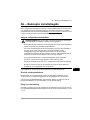
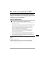
DA – Hurtig installationsvejledning
Denne guide er en kortfattet vejledning i, hvordan man installerer
frekvensomformeren. Hvis du vil have mere detaljerede instruktioner, tekniske
retningslinjer, tekniske data og komplette sikkerhedsinstruktioner, kan du se
hardwaremanualen (www.abb.com/drives
: Vælg Document Library, og søg efter
dokumentnummer 3AUA0000099663 (på engelsk).
Følg sikkerhedsinstruktionerne
Gulvmaterialet under frekvensomformeren skal være ikke-brandbart.
Vælg effektkabler
Vælg en størrelse til kablerne i henhold til lokale forskrifter til at bære den nominelle
strøm, der er anført på mærket med typebetegnelsen på din frekvensomformer.
Typiske størrelser på strømkabler vises i tabel B på side 92. Du kan se betingelserne
for størrelsen i hardwaremanualen.
Sørg for kølingen
Se tabel B på side 92 for tabene og frekvensomformeren gennemstrømning af
kølende luft. Frekvensomformerens tilladte driftstemperaturområde uden reduktion er
-15 til +40 °C.
ADVARSEL! Manglende overholdelse af disse instruktioner kan medføre
fysiske skader eller dødsfald eller skade på udstyret:
• Kun autoriserede elinstallatører må udføre installation og vedligeholdelse af
frekvensomformeren.
• Undlad at arbejde med frekvensomformeren, motorkablet eller motoren, når
tilslutning til nettet er foretaget. Vent 5 minutter, efter at netspændingen er
frakoblet, så mellemkredskondensatorerne kan aflades, inden arbejdet med
frekvensomformeren, motoren eller motorkablet påbegyndes.
• Der må ikke arbejdes med signalkablerne, når netspændingen er tilsluttet
frekvensomformeren eller de eksterne styrekredse.
• Undgå, at der trænger smuds fra boringer og sliberester ind i
frekvensomformeren under installation.
• Tilslut ikke frekvensomformeren til en større spænding end der er angivet på
mærkatet med typebetegnelse.

16 DA – Hurtig installationsvejledning
EN
EN
DA
DE
ES
FI
FR
IT
NL
PT
RU
SV
TR
CN
Beskyt frekvensomformeren og netkablet
Se tabellen B på side 92. Kontrollér, at reaktionstiden for sikringen er under 0,5
sekunder.
Installer frekvensomformeren på væggen
Se figuren A på side 91.
Kontroller isoleringen på input- og motorkabler samt
motoren
Kontrollér isoleringen af indgangskablet i overensstemmelse med de nationale
forskrifter, inden det tilsluttes frekvensomformeren.
Se figuren D på side 93. Tilslut motorkabelskærmen i motorenden. Opnå minimal
interferens ved at lave en 360 graders jording ved kabelgennemføringen eller holde
den snoede kobberskærm kort.
Kontroller isoleringen af motorkabler og motor, når kablet er koblet fra
frekvensomformeren, se figur E på side 93. Mål isolationsmodstanden mellem hver
faseleder og beskyttelsesjordlederen med en målespænding på 1000 V DC.
Isolationsmodstanden på en ABB-motor skal være større end 100 Mohm
(referenceværdi ved 25 °C eller 77 °F). Oplysninger om isolationsmodstanden på
andre motorer kan findes i producentens vejledninger. Bemærk! Fugt inden i
motorhuset vil reducere isolationsmodstanden. Hvis der er mistanke om fugt, skal
motoren tørres, og målingen gentages.
Tilslut netkablerne.
Se figurerne C og F og på side 92 og 93. Anvend et skærmet symmetrisk kabel til
motorkablingen.
1. Fjern frontdækslet. IP21-enheder
: Løsn låsesplitten med en skruetrækker (a) og
løft dækslet ud fra bunden (b).
2. IP21-enheder
: Fjern kabelindgangskassens dæksel ved at løsne
monteringsskruerne.
3. Fastgør advarselsmærkatet om restspænding på det lokale sprog ved siden af
styrekortet.
4. Fjern sidepladerne på kabelindgangskassen ved at løsne monteringsskruerne.
5. Fjern afskærmningen på effektkabelterminalerne ved at løsne splitterne i siderne
med en skruetrækker og løfte (a). Trykkes huller ud til kablerne (b).
6. R8, R9:
Hvis der monteres parallelle kabler, slå afskærmningerne ud på
effektkabelterminalerne til de kabler, som skal installeres.

DA – Hurtig installationsvejledning 17
EN
DA
DE
ES
FI
FR
IT
NL
PT
RU
SV
TR
CN
7. Skær tilstrækkeligt store huller i gummimufferne. Træk gummimufferne på
kablerne. Forbered kabelenderne. Før kablerne gennem hullerne på bundpladen,
og sæt mufferne fast i hullerne.
8. Jord kabelskærmene 360 grader under jordforbindelsesaflastningerne.
9. Forbind de snoede kabelskærme til de jordede terminaler.
10. Forbind lederne på indgangs- og motorkablerne. Stram skruerne.
11. Enheder med valgmulighed +D150:
Forbind modstandskablets lederne til
terminalerne R+ og R-.
12. Hvis der monteres parallelle kabler
, monteres jordingsplinterne til dem. Gentag
trin 7–12.
13. Genmonter afskærmningen til strømterminalerne.
14. Montér sidepladerne på kabelindgangskassen.
15. Fastgør kablerne uden for enheden mekanisk.
Tilslut styrekablerne
Se figuren G.
1. Installér styrekablets jordingsplinte i kabelindgangens kasse.
2. Klip passende huller i gummimufferne, og skub mufferne på kablerne. Før
kablerne gennem hullerne på bundpladen, og sæt mufferne fast i hullerne.
3. Afisoler kabelenderne, og skær dem af i en passende længde (bemærk
jordledernes ekstra længde).
4. Jord de ydre skærme på alle kabler 360 grader ved en jordingsklemme i
kabelindgangens kasse.
5. Jord de skærmede, snoede kabler til en jordklemme under styrekortet. Lad den
anden ende af skærmene være utilkoblet, eller slut dem indirekte til jord med en
højfrekvenskondensator på nogle få nanofarad (f.eks. 3,3 nF / 630 V).
6. Forbind kablets ledere til de korrekte klemmer på styrekortet (se side 19).
7. Forbind de valgfrie moduler, hvis de indgår i leverancen.
8. Genmonter frontdækslet.
Bemærkning om feltbus-kabelføring. Se figur H.
1. Installer den yderligere forankringshylde.
2. Du skal forankre de yndre afskærmninger på 360 grader ved en jordklemme.
3. Bank huller ud i dækslet på kabelindgangsboksen, hvor kablerne skal monteres.
Monter dækslet på kabelindgangsboksen.

18 DA – Hurtig installationsvejledning
EN
EN
DA
DE
ES
FI
FR
IT
NL
PT
RU
SV
TR
CN
4. Slut stikket til feltbusmodulet.
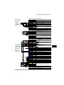
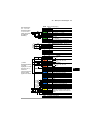
I/O-standardtilslutninger
I/O-standardtilslutninger til fabriksmakroen for det primære styreprogram for ACS880
er vist herunder.

DA – Hurtig installationsvejledning 19
EN
DA
DE
ES
FI
FR
IT
NL
PT
RU
SV
TR
CN
Fejl
XPOW Ekstern indgangseffekt
1 +24VI
24 V DC, 2 A
2 GND
XAI Referencespænding og analoge indgange
1 +VREF 10 V DC, R
L
1…10 kohm
2 -VREF -10 V DC, R
L
1…10 kohm
3 AGND Jord
4 AI1+ Hastighedsreference 0(2)…10 V, R
i
>
200 kohm
5 AI1-
6 AI2+
Som standardindstilling ubenyttet.
0(4)…20 mA, R
i
= 100 ohm
7 AI2-
J1 J1 AI1 jumper til valg af strøm/spænding
J2 J2 AI2 jumper til valg af strøm/spænding
XAO Analog udgang
1 AO1 Motorhastighed o/min 0…20 mA, R
L
<
500 ohm
2 AGND
3 AO2
Motorstrøm 0…20 mA, R
L
< 500 ohm
4 AGND
XD2D Drev til drev-forbindelse
1 B
Drev til drev-forbindelse
2 A
3 BGND
J3 J3 Afbryder til drev til drev-link
XRO1, XRO2, XRO3 Relæudgange
11 NC
Startklar
250 V AC / 30 V DC
2 A
12 COM
13 NO
21 NC
Kører
250 V AC / 30 V DC
2 A
22 COM
23 NO
31 NC
Fejl(-1)
250 V AC / 30 V DC
2 A
32 COM
33 NO
XD24 Digital interlock
1 DIIL Start frigiv
2 +24VD +24 V DC 200 mA
1)
3 DICOM Jording af digital indgang
4 +24VD +24 V DC 200 mA
1)
5 DIOGND Jording af digital indgang/udgang
J6 Afbryder til valg af jord
XDIO Digitale indgange/udgange
1 DIO1 Output: Startklar
2 DIO2 Output: Kører
XDI Digital indgang
1 DI1 Stop (0) / Start (1)
2 DI2 Forlæns (0) / Baglæns (1)
3 DI3 Reset
4 DI4 Acceleration og deceleration vælg
5 DI5 Konstant hastighed 1 (1 = On)
6 DI6 Som standardindstilling ubenyttet.
XSTO Safe torque off
1 OUT1
Safe torque off. Begge kredse skal være
lukkede, for at frekvensomformeren kan
starte.
2 SGND
3 IN1
4 IN2
X12 Modulforbindelse med sikkerhedsfunktioner
X13 Tilslutning til betjeningspanel
X205 Tilslutning til hukommelsesenhed
Ledningsstørrelse:
0,5 … 2,5 mm
2
Fastspændings-
momenter:
0,5 N·m til både
trådledere og stive
ledere.
1)
Den totale
belastningskapa-
citet for disse
udgange er 4,8 W
(200 mA / 24 V)
minus den strøm,
der går til DIO1 og
DIO2.

20 DA – Hurtig installationsvejledning
EN
EN
DA
DE
ES
FI
FR
IT
NL
PT
RU
SV
TR
CN
Sayfa yükleniyor...
Sayfa yükleniyor...
Sayfa yükleniyor...
Sayfa yükleniyor...
Sayfa yükleniyor...
Sayfa yükleniyor...
Sayfa yükleniyor...
Sayfa yükleniyor...
Sayfa yükleniyor...
Sayfa yükleniyor...
Sayfa yükleniyor...
Sayfa yükleniyor...
Sayfa yükleniyor...
Sayfa yükleniyor...
Sayfa yükleniyor...
Sayfa yükleniyor...
Sayfa yükleniyor...
Sayfa yükleniyor...
Sayfa yükleniyor...
Sayfa yükleniyor...
Sayfa yükleniyor...
Sayfa yükleniyor...
Sayfa yükleniyor...
Sayfa yükleniyor...
Sayfa yükleniyor...
Sayfa yükleniyor...
Sayfa yükleniyor...
Sayfa yükleniyor...
Sayfa yükleniyor...
Sayfa yükleniyor...
Sayfa yükleniyor...
Sayfa yükleniyor...
Sayfa yükleniyor...
Sayfa yükleniyor...
Sayfa yükleniyor...
Sayfa yükleniyor...
Sayfa yükleniyor...
Sayfa yükleniyor...
Sayfa yükleniyor...
Sayfa yükleniyor...
Sayfa yükleniyor...
Sayfa yükleniyor...
Sayfa yükleniyor...
Sayfa yükleniyor...
Sayfa yükleniyor...
Sayfa yükleniyor...
Sayfa yükleniyor...
Sayfa yükleniyor...
Sayfa yükleniyor...
Sayfa yükleniyor...
Sayfa yükleniyor...
Sayfa yükleniyor...
Sayfa yükleniyor...
Sayfa yükleniyor...
Sayfa yükleniyor...
Sayfa yükleniyor...
Sayfa yükleniyor...
Sayfa yükleniyor...
Sayfa yükleniyor...
Sayfa yükleniyor...
Sayfa yükleniyor...
Sayfa yükleniyor...
Sayfa yükleniyor...
Sayfa yükleniyor...
Sayfa yükleniyor...
Sayfa yükleniyor...
Sayfa yükleniyor...
Sayfa yükleniyor...
Sayfa yükleniyor...
Sayfa yükleniyor...
Sayfa yükleniyor...
Sayfa yükleniyor...
Sayfa yükleniyor...
Sayfa yükleniyor...
Sayfa yükleniyor...
Sayfa yükleniyor...
Sayfa yükleniyor...
Sayfa yükleniyor...
-
 1
1
-
 2
2
-
 3
3
-
 4
4
-
 5
5
-
 6
6
-
 7
7
-
 8
8
-
 9
9
-
 10
10
-
 11
11
-
 12
12
-
 13
13
-
 14
14
-
 15
15
-
 16
16
-
 17
17
-
 18
18
-
 19
19
-
 20
20
-
 21
21
-
 22
22
-
 23
23
-
 24
24
-
 25
25
-
 26
26
-
 27
27
-
 28
28
-
 29
29
-
 30
30
-
 31
31
-
 32
32
-
 33
33
-
 34
34
-
 35
35
-
 36
36
-
 37
37
-
 38
38
-
 39
39
-
 40
40
-
 41
41
-
 42
42
-
 43
43
-
 44
44
-
 45
45
-
 46
46
-
 47
47
-
 48
48
-
 49
49
-
 50
50
-
 51
51
-
 52
52
-
 53
53
-
 54
54
-
 55
55
-
 56
56
-
 57
57
-
 58
58
-
 59
59
-
 60
60
-
 61
61
-
 62
62
-
 63
63
-
 64
64
-
 65
65
-
 66
66
-
 67
67
-
 68
68
-
 69
69
-
 70
70
-
 71
71
-
 72
72
-
 73
73
-
 74
74
-
 75
75
-
 76
76
-
 77
77
-
 78
78
-
 79
79
-
 80
80
-
 81
81
-
 82
82
-
 83
83
-
 84
84
-
 85
85
-
 86
86
-
 87
87
-
 88
88
-
 89
89
-
 90
90
-
 91
91
-
 92
92
-
 93
93
-
 94
94
-
 95
95
-
 96
96
-
 97
97
-
 98
98


ABB ACS880-01-09A8-7 Quick Installation Manual
- Tip
- Quick Installation Manual
diğer dillerde
- español: ABB ACS880-01-09A8-7
- français: ABB ACS880-01-09A8-7
- italiano: ABB ACS880-01-09A8-7
- svenska: ABB ACS880-01-09A8-7
- polski: ABB ACS880-01-09A8-7
- Deutsch: ABB ACS880-01-09A8-7
- português: ABB ACS880-01-09A8-7
- English: ABB ACS880-01-09A8-7
- dansk: ABB ACS880-01-09A8-7
- русский: ABB ACS880-01-09A8-7
- suomi: ABB ACS880-01-09A8-7
- Nederlands: ABB ACS880-01-09A8-7
İlgili makaleler
-
ABB ACS880-01 Series Quick Installation Manual
-
-
-
-
ABB ACS880-04 drive modules Quick Installation Manual
-
ABB ACS850-04 series Quick Installation Manual
-
-
-
ABB ACS880 Series Quick Start Up Manual
-